gauge assembly HONDA CR-V 1999 RD1-RD3 / 1.G Workshop Manual
[x] Cancel search | Manufacturer: HONDA, Model Year: 1999, Model line: CR-V, Model: HONDA CR-V 1999 RD1-RD3 / 1.GPages: 1395, PDF Size: 35.62 MB
Page 72 of 1395
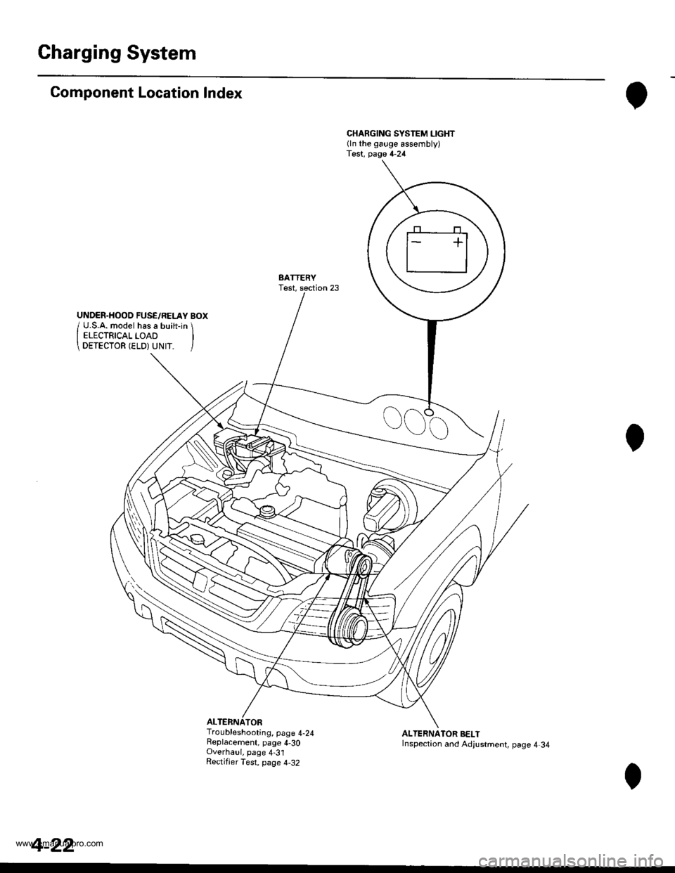
Charging System
Component Location Index
ALTERNATOR
CHARGING SYSTEM LIGHT(ln the gauge assembly)Test, page 4-24
BATTERYTest,
Troubleshooting, page 4-24Replacement, page 4-30Overhaul, page 4-31Rectifjer Test, page 4,32
ALTERNATOR BELTInspection and Adjustment, page 4 34
4-22
www.emanualpro.com
Page 86 of 1395
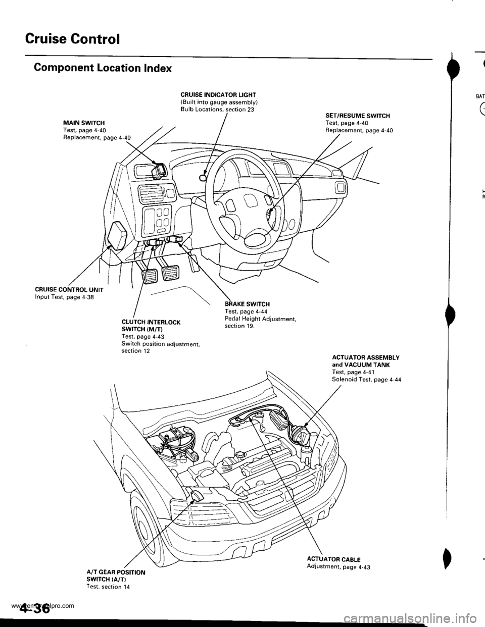
Gruise Control
Component Location Index
CRUISE CONTROL UNITInput Test, page 4 38
CRUISE INDICATOR LIGHT(Built into gauge assembly)Bulb Locations. section 23
swtTcHTest, page 4-44
SET/RESUME SWITCHTest, page 4 40Beplacement, page 4-40
ACTUATOfi ASSEMBLYand VACUUM TANKTest, page 4 41Solenoid Test, page 4 44
CLUTCH INTERLOCKswrTcH {M/T)Test, page 4-43Switch poskion adjustment,section 12
Pedal Height Adjustment,section 19.
ACTUATOR CAELEAdjustment, page 4-43A/T GEAB POSITIONswlTcH (A/TlTest, section '14
+36
I
BAT
(
I
www.emanualpro.com
Page 89 of 1395

Disconnest the lilP connector from the control unit.
Csvity WireTest condition
R€conn€ct tho 14P connGctor to the control unit.
Test: Desired resultPossible cause it result is not obtained
BRNAr'VHTUnder all conditionsCheck for resistance to groundl
There should be 80 - 120 o.
Faulty actuator solenoid
Poor ground (G202)
An open in the wire1BRNUnder all conditionsCheck for resistance to groundl
There should be 40 - 60 0.
11BRN/BLKUnder all conditionsCheck for resistance to ground:
There should be 70 - 110 O.
2GRY
lgnition switch ON (ll),
main switch ON and
brake pedal depressed,
then released
Check for voltage to ground:
There should be 0 V with the pedal
depressed and battery voltage with
the pedal released.
. Faulty brake switch. An open in the wire
BLKUnder all conditionsCheck for continuity to ground:
There should be continuity.
. Poor ground (G401). An open in the wire
5GRNMHT
Brake pedal depressed,
then released
Check for voltage to ground:
There should be battery voltage with
the pedal depressed, and 0 V with
the pedal released.
Blown No.52 1'15 Alfuse in the
under-hood fuse/relay box
Faulty brake switch
An open in the wire
LT GRN/
RED
Set button pushedCheck for voltage to ground:
There should be battery voltage.Blown No. 52 {'15 A} fuse in the
under-hood fuse/relay box
Faulty horn relay
Faulty sevresume switch
Faulty cable reel
An open in the wire7LT GRN/
BLK
Resume button pushed
10RED/BLU
lgnition switch ON lll)Attach to ground:
Cruise indicator light in the gauge
assembly should come on.
Elown bulbBlown No. 25 (7.5 A) tuse in theunder-dash fuse/relay box
Faulty dimming circuit in the gauge
assembly
An open in the wire
ELU^r'r'HT
lgnitjon switch ON {ll}and main switch ON;
raise the front of the
vehicle, block one wheel
and rotate the other
wheel slowly.
Check for voltage between the
ELUA/VHT @ and BLK O terminalsl
There should be 0 - 5 V or more-0 - 5 V or more repeatedly.
Faulty vehicle speed sensor (VSS)
An open in the wire
r3LT GRN
lgnition switch ON {ll}and main switch ONCheck for voltage to ground:
There should be battery voltage.
Blown No. 14 (7.5 A) fuse in theunder-dash fuse/relay box
Faulty main switch
An open in the wire
l4PNK
A'/T: Shift lever in E, EotE
lvl/T: Clutch pedal
releaseo
Check for continuity to ground:
There should be continuity.NOTE: There should be no continu-
ity when the shift lever is in otherpositions or when the clutch pedal is
oepresseo.
Faulty A/f gear position switch 1A,/TlFaulty or misadjusted clutch switch
fi{/r)Poor ground (G101)
An open in the wire
BLU
Start tho engine. turnthe main switch ON, anddrive the vehicle over 25
mph (40 km/h)with the
crurse control set
Check for voltage to ground:
There should be approx.5 V
. Faulty cruise control unit. Shod to ground
*: '98 - 00 models with Automatic Transmission.
4-39
www.emanualpro.com
Page 284 of 1395
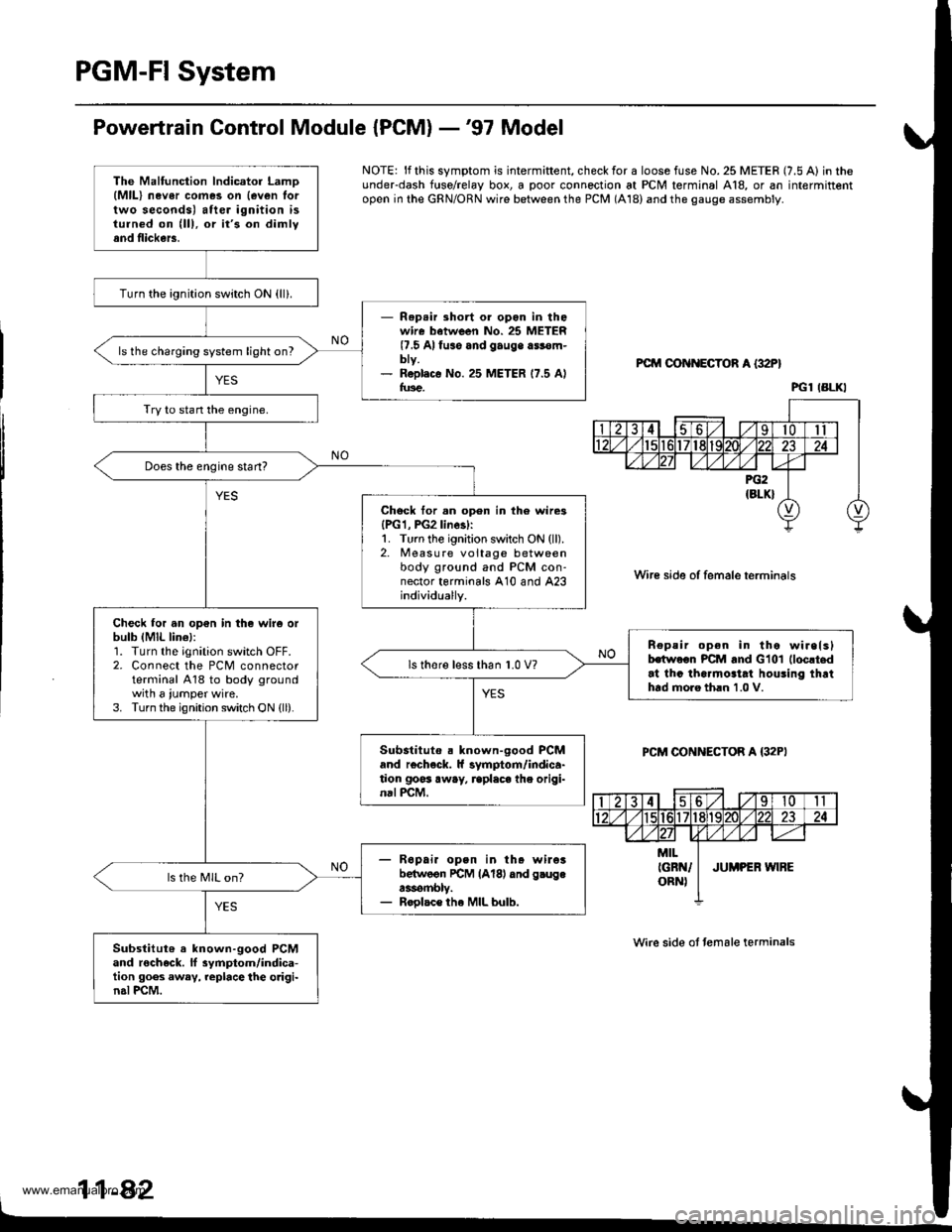
PGM-FI System
Powertrain Control Module {PCM} -'97 Model
NOTE: lf this symptom is intermiftent, check for a loose fuse No. 25 METER (7.5 A) in theunderdash f{rse/relay box, a poor connection at PCM terminal A18, or an intermittentopen in the GRN/ORN wire between the PCM (A18) and the gauge assembly.
PCM OON ECTOR A {32P}
Wire side of female terminals
PCM CONNECTOR A {32PI
Wire side ot temale terminals
11-42
The Malfunction lndicator LamD(MlL) nev6r comes on {even lortwo seconds) after ignition isturned on (lll, or it's on dimlyand flickers.
Turn the ignition switch ON {ll}.
- Rep.ir short or opon in thowire batween No. 25 METER(7.5 Alfuso and gauge a$€m-bty.- R6pl.c€ No. 25 METER 17.5 Alfus€.
ls the charging system light on?
Try to stan the engine.
Does the engine start?
Chock tor.n open in th6 wire3{PG1, PG2linesl:1. Turn the ignition switch ON (ll).2. Measure voltage betweenbody ground and PCM con-nector terminals A10 and A23individually.
Check for an op€n in the wir6 orbulb (MlL lin€l:1. Turn the ignition switch OFF.2. Connect the PCM connectorterminal A18 to body groundwith a iumper wire.3. Turn the ignition switch ON {ll).
n€peir open in tho wirelslhwoon PCM and Glol (loc!t.d
at thc tha.mo3tat houling thrthtd moro th.n 1.0 V.
ls thore l€ss than 1.0 V?
Substituto . known-good PCMand r€check. ll symptom/indica-tion goss away, rcplaca the origi-nal PCM.
- R6pai. open in th. wileibelwoon rcM lAl8l dnd g.ugea3rombly.- Roolac€ the MIL bulb.
ls the MIL on?
Substitut6 a known-good PCMand rocheck. ll 3ymptom/indica-tion goes away, replace the o.igi-n.l PCM.
PGl IBLKI
www.emanualpro.com
Page 285 of 1395
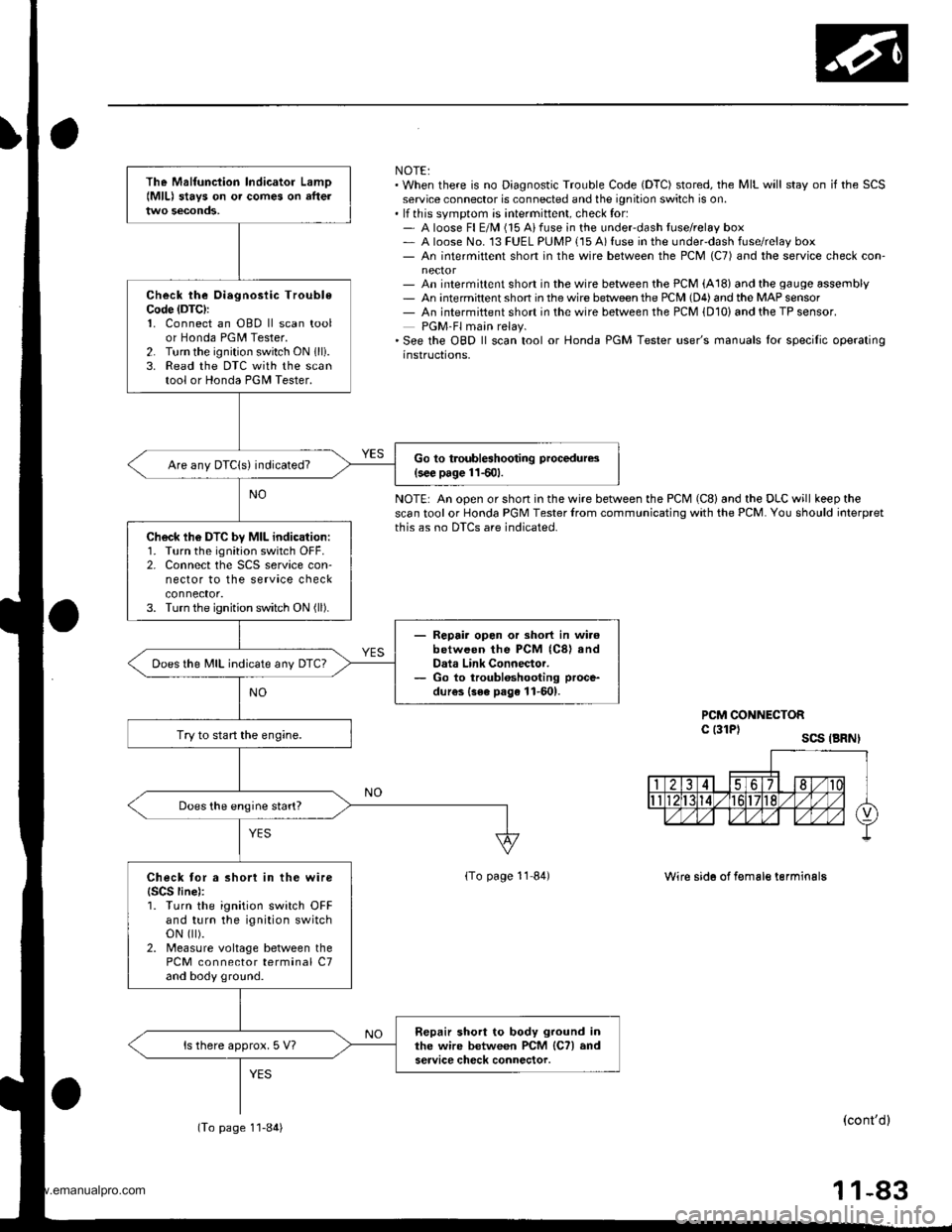
NOTE:. When there is no Diagnostic Trouble Code (DTC) stored, the MIL will stay on if the SCSservice connector is connected and the ignition switch is on.. lf this svmotom is intermittent, check for:- A loose Fl E/M (15 Aifuse in the underdash tuse/relay box- A loose No. 13 FUEL PUMP {15 A) fuse in the under-dash fuse/relay box- An intermittent short in the wire between the PCM (C7) and the service check con-
- An intermittent short in the wire between the PCM (A18) and the gauge assembly- An intermittent shon in the wire betlveen the PCM (D4) and the MAP sensor- An intermiftent short in the wire between the PCM {D10) and the TP sensor.PGM-Fl main relay.'See the OBD ll scan tool or Honda PGM Tester user's manuals lor specilic operatinginstructions,
NOTE: An open or short in the wire between the PCM (C8) and the DLC will keep thescan tool or Honda PGM Tester lrom communicating with the PCM. You should ioterpretthis as no DTCS are indicated.
PCM CONNECTORc l3lPl scs .BRNI
lTo page 11 84)Wire sid6 of f€male terminalg
(cont'dl
11-83
The Malfunciion lndicator Lamo{MlL) stavs on o. comes on afteltwo seconds,
Check the Oiegnosiic TroubleCode (DTC):
1. Connect an OBD ll scan toolor Honda PGM Tester.2. Turn the ignition switch ON 1lli.3. Read the DTC with the scantool or Honda PGII Tester.
Go to troubleshooting procedures(s€€ page 11501.Are any DTCIs) indicated?
Ch6ck lh6 DTC by MIL indication:1. Turn the ignition switch OFF.2. Connect the SCS service con-nector to the service checkconnector.3. Turn the ignition switch ON (ll).
- Repair opon or short in wi.6between the PCM (C8) andData Link Connector.- Go to troubloshooting proce-
dur€s {3ee page 11-601.
Does the MIL indicate any DTc?
Try to start the engine.
Does the engine start?
Check tor a short in the wire{SCS line):1. Turn the ignition switch OFFand turn the ignition switchoN flt).2. Measure voltage between thePCM connector terminal C7and body ground.
Repair short to body ground inthe wire between PCM lCTl andservice check connector.ls there approx. 5 V?
(To page 1'l-84)
www.emanualpro.com
Page 288 of 1395
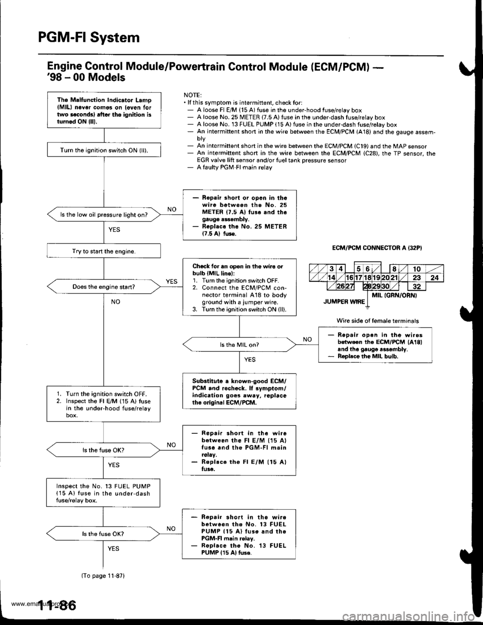
PGM-FI System
Tho Maltunction Indicator Lamo(MlL) n6Yor como3 on leven lortwo laconds) rft6r tho ignhion isturnod ON {lll.
Turn th6 ignition switch ON (ll).
- Repair lhort or opcn in thowire between the No. 25METER 17.5 Al fu3e snd thegauge assembly.- Repl.co the No. 25 METER17.5 Al fus€.
ls the low oil pressure light on?
Try to start the engine.
Chock for an opsn in th€ wiro orbulb {MlL line,:1. Turn the ignition switch OFF.2. Connect the ECM/PCM con-nector terminal A18 to bodyground with a iumper wire.3. Turn the ignition switch ON (ll).
Rep.ir open in the wi.osbotween the ECM/FCM lA18land the gaugo rasombly.Roplece the MIL bulb.
ls th6 MIL on?
Substitute a known-good ECM/PCM and rochock. lf rymptom/indication goes eway, replacetho o gind ECM/PCM.
Turn the ignition switch OFF.Inspect the Fl E/M 115 A) tusein the undeFhood fuse/relaybox.
- Repair short in the wirebetween lhe Fl E/M (15 AlfusG and the PGM-Fl m.in.slay.- Roplsce th€ Fl E/M (15 Alfu3€.
Inspect the No. 13 FUEL PUMP(15 A) fuse in the under-dashfuse/relay box.
- Repair short in th6 wirebetween tho No. 13 FUELPUMP 115 A) luse and thePGM-FI main .elay.- ReDlace tho No. 13 FUELPUMP 115 Al tuse.
Engine Gontrol Module/Powertrain Control Module (ECM/PCM) -'98 - 00 Models
NOTE:. lf this symptom is intermittent, check tor:- A loose Fl E/M {15 A) fuse in the under-hood fuse/relay box- A loose No. 25 METER {7.5 A) fuse in the under-dash fuse/relay box- A loose No. 13 FUEL PUMP (15 Alfuse in the underdash fuse/rolay box- An intermiftent short in the wire between the ECM/PCM (A18) and the gauge assem-
- An int€rmiftent short in the wire between the ECM/PCM (C19) and the MAP sensor- An intermiftent short in the wire between rhe ECM/PCM (C28), the TP sensor, theEGR valve lift sensor and/or {uel tank Dressure sensor- A laulty PGM-FI main relay
ECM/PCM CONNECTOR A (32P}
Wire side of female terminals
(To page 11-871
www.emanualpro.com
Page 388 of 1395
Fuel Supply System
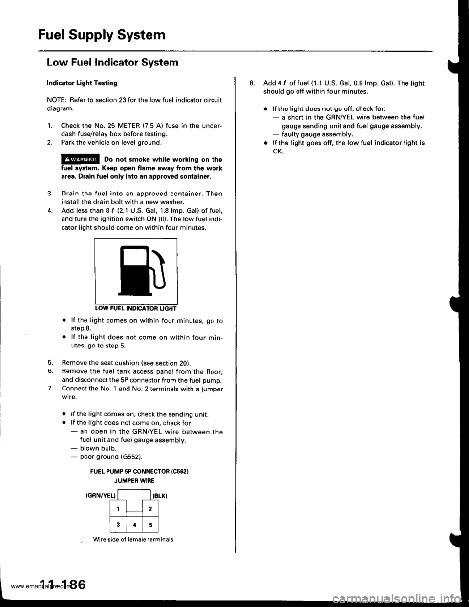
Low Fuel Indicator System
Indicator Light Testing
NOTE: Refer to section 23forthe lowfuel lndicator circuit
clragram.
1. Check the No. 25 METER (7.5 A) fuse in the under-
dash fuse/relay box before testing.
2. Park the vehicle on level ground.
@ Do not smoke while working on the
fuel system. Keep open flame away trom the work
aroa. Drain fuel only into an approved container.
Drain the fuel into an aoDroved container. Then
install the drain bolt with a new washer.
Add less than 8 f (2.1 U.S. Gal. 1.8 lmp. Gal) of fuel,
and turn the ignition switch ON {ll). The low fuel indi-
cator light should come on within four minutes.
INDICATON LIGHT
. lf the light comes on within four minutes, go tostep 8.
. lf the light does not come on within four min-
utes. go to step 5.
Remove the seat cushion (see section 20).
Remove the fuel tank access panel from the floor,
and disconnect the 5P connector from the fuel pump,
Connect the No. 1 and No. 2 terminals with a jumper
wire.
. lf the lightcomeson, checkthe sending unit.. lf the light does not come on, check for:- an open in the GRN/yEL wire between thefuel unit and fuel gauge assembly.- blown bulb.- poor ground (G552).
FUEI- PUMP 5P CONNECTOR (C562)
JUMPER WIRE
IGRN/YEL}
7.
1 1-1 86
Wire sid€ ol tem€le terminals
8. Add 4 / of fuel (1.1 U.S. Gal, 0.9 lmp. Gal). The light
should go off within four minutes.
. lJ the light does not go off, check for:- a short in the GRNA/EL wire between the fuel
gauge sending unit and fuel gauge assembly.- faulty gauge assembly.
. lf the light goes off, the low fuel indicator light is
oK.
www.emanualpro.com
Page 469 of 1395
Countershaft Assembly
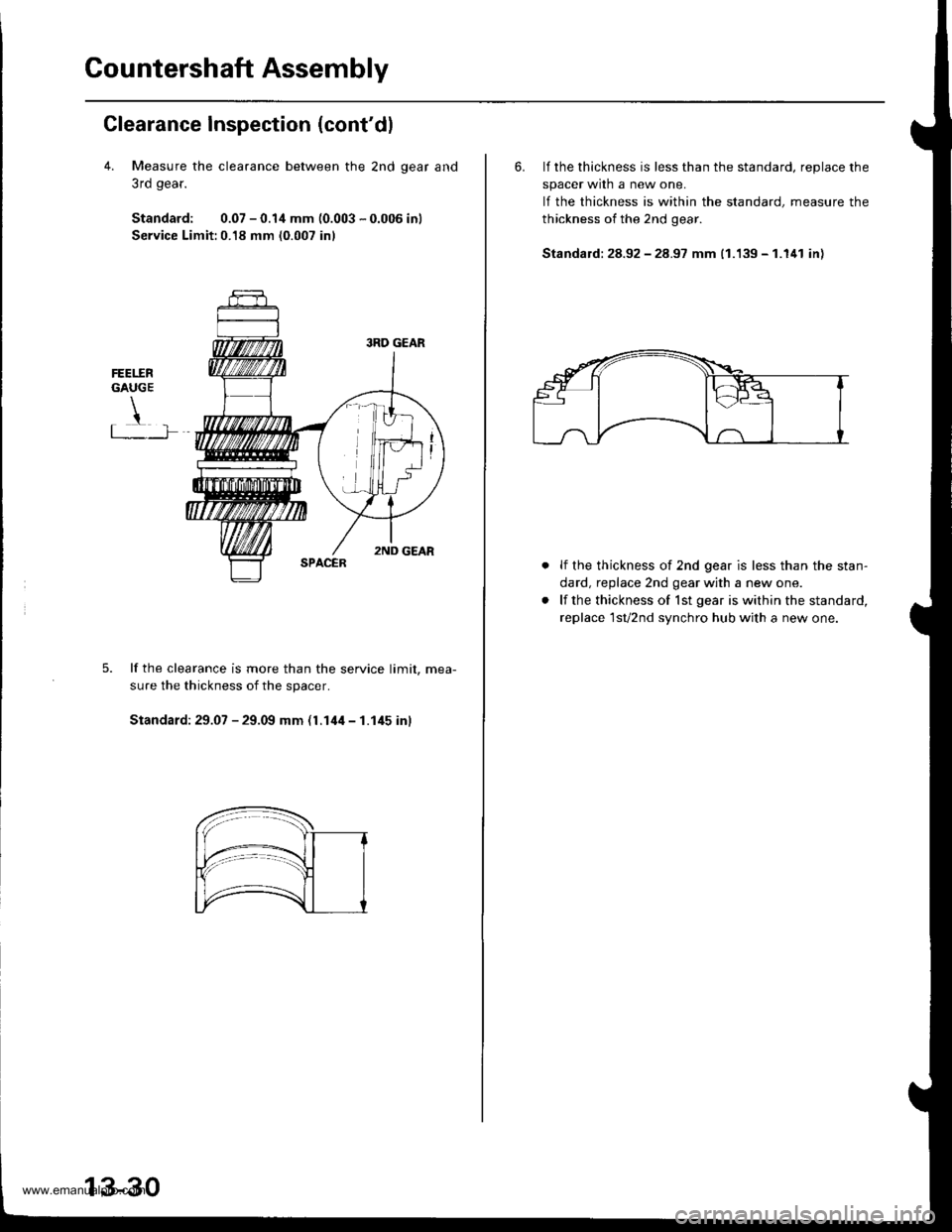
Clearance Inspection (cont'dl
4. Measure the clearance between the 2nd qear and
3rd gear.
Standard: 0.07 - 0.1,1 mm (0.003 - 0.006 inl
Service Limit:0.18 mm (0.007 inl
FEET.ERGAUGE
!t .�-]�
lf the clearance is more than the service limit. mea-
sure the thickness of the spacer.
Standard: 29.07 - 29.09 mm (l.14il - 1.145 inl
13-30
6. lf the thickness is less than the standard, reDlace the
spacer wrln a new one.
lf the thickness is within the standard, measure the
thickness of the 2nd gear.
Standald: 28.92 - 28.97 mm (1.139 - 1.141 in)
lf the thickness of 2nd gear is less than the stan-
dard, replace 2nd gear with a new one.
lf the thickness of lst gear is within the standard,
replace 1sv2nd synchro hub with a new one.
www.emanualpro.com
Page 503 of 1395
Mainshaft Thrust Clearance
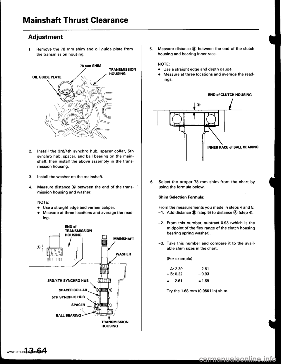
Adjustment
l. Remove the 78 mm shim
the transmission housing.
4.
and oil guide plate from
Install the 3rd/4th synchro hub, spacer collar, sth
synchro hub, spacer, and ball bearing on the main-
shaft. then install the above assembly in the trans-
mission housing.
lnstallthe washer on the mainshaft.
Measure distance @ between the end of the trans-
mission housing and washer,
NOTE:
. Use a straight edge and vernier caliper.
. Measure at three locations and average the read-
Ing.
END otTRANSMISSION
MAINSHAFT
WASHER
3RD/4TH SYNCHRO HUB
SPACER COLLAR
sTH SYNCHRO HUB
SPACER
78 mm SHIM
13-64
BALL BEARING
5, Measure distance @ between the end of the clutch
housing and bearing inner race.
NOTE:
. Use a straight edge and depth gauge.
. Measure at three locations and avorage the read-
Ings.
END ot CLUTCH HOUSING
BEARING
Select the proper 78 mm shim from the chan by
using the formula below.
Shim S€lection Formula:
From the measurements you made in steps 4 and 5:-1. Add distance @ (step 5) to distance @ (step 4).
-2. From this number. subtract 0.93 (which is the
midpoint of the flex range of the clutch housing
bearing spring washer).
-3. Take this number and compare it to the avail-
able shim sizes in the chart.
(For example)
A: 2.39 2.61
+ Bi O.22 - 0.93
= 2.61= 1.68
Try the 1.68 mm (0.0661 in) shim.
www.emanualpro.com
Page 518 of 1395
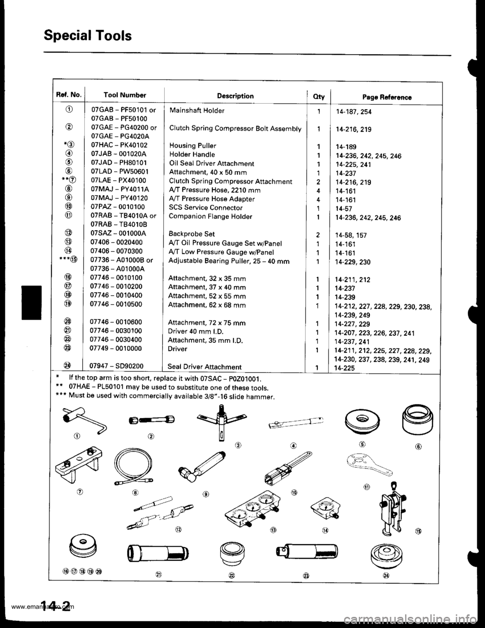
Ref. No.
^tl)
@
*rar
@
@
,-o
@
o
@
@
@
@
@.--@
@
@
@
@
@
@
@
@
@
Tool NumberDescriptionOty I Pago Referonc€
Mainshaft Holder
Clutch Spring Compressor Bolt Assembly
Housing Puller
Holder Handle
Oil Seal Driver Aftachment
Attachment, 40 x 50 mm
Clutch Spring Compressor Attachment
Ay'T Pressure Hose, 2210 mm
IVT Pressure Hose Adapter
SCS Service Connector
Companion Flange Holder
Backprobe Set
lVT Oil Pressure Gauge Set w/Panel
A,/T Low Pressure Gauge w/Panel
Adjustable Bearing Puller, 25 - 40 mm
Anachment, 32 x 35 mm
Attachment, 37 x 40 mm
Attachment. 52 x 55 mm
Attachment. 62 x 68 mm
Attachment, 72 x 75 mm
Driver 40 mm l.D.
Attachment, 35 mm LD.
Driver
07GAB - PF50101 or
07GAB - PF50100
07GAE - PG40200 or
OTGAE _ PG4O2OA
07HAC - PK40102
07JAB - 001020A
07JAD - PH80101
07LAD - PW50601
07LAE - PX40100
OTMAJ - PY4O114
07MAJ - PY40120
07 PAZ - 0010100
07RAB - TB4010A or
07RAB.TB40lOB
07sAz - 001000A
07406 - 0020400
07406 - 0070300
07736 - 4010008 or
07736 - A010004
07746 - 0010100
07746 - 0010200
07746 - 0010400
07746 - 0010500
07746 - 0010600
07746 - 0030100
07746 - 0030400
07749 - 0010000
07947 - SD90200Seal Driver Aftachment
1
1
1
1,l
1
I
2
1'l
1
I
1
1
1
1
1
1
I
1
14-181 , 254
14-216,219
14-189't4-236,242,245,246
't 4-225, 241
14-237
14-216,2't9
14-161
14- 161
14-57
14-236,242,245,246
14-58, 157
14-161
14-161'14-229,230
14-211, 2't2
14-231
14-239
14-212, 227 , 228,229, 230, 238,
14-239, 249
14-221 ,229't 4-207 , 223,226, 237 , 241
14-237,241
1 +21 1, 2't2, 225, 227, 228, 229,
14-230, 237 , 238, 239, 24't, 249't4-225
lf the top arm is too short, replace it with 07SAC - pOZ01OO1.
07HAE - PL50101 may be used to substitute one of these tools.Must be used with commercially available 3/8"-16 slide hammer.
E----G
@@@@@
@
tvj
'
@@@)
14-2
www.emanualpro.com