Connectors HONDA CR-V 2000 RD1-RD3 / 1.G Workshop Manual
[x] Cancel search | Manufacturer: HONDA, Model Year: 2000, Model line: CR-V, Model: HONDA CR-V 2000 RD1-RD3 / 1.GPages: 1395, PDF Size: 35.62 MB
Page 1130 of 1395
Troubleshooting
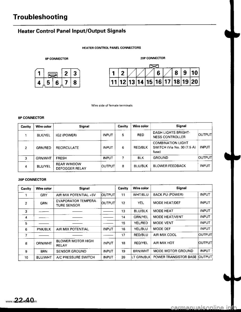
Heater Control Panel Input/Output Signals
HEATER CONTROL PANEL CONNECTORS
8P CONNECTOR
Wire side of female terminals
2OP CONNECTOR
8P CONNECTOR
Cavitylrvire cololSignalCavityWire cololSignal
'lBLK/TE LIG2 (POWER)INPUTREDDASH LIGHTS ERIGHT-
NESS CONTROLLERCUTPUT
2GRN/REDRECIRCULATEINPUTRE D/BLK
COMBINATION LIGHT
SWITCH (Via No. 30 (7.5 A)
fuse)
INPUT
GRN/VVHTFRESHINPUT1BLKGROUNDOUTPUT
BLUI/ELREAR WINDOW
DEFOGGER RELAYCUTPUT8BLU/BLKBLOWER FEEDBACKINPUT
20P CONNECTOR
CavityWire colorSignalCavityWire colorSignal
1GRYAIR MIX POTENTIAL +5VOUTPUT'llWHT/BLUBACK PU (POWER)INPUT
2GRNEVAPORATOR TEMPERA.
TURE SENSOROUTPUT12YELMODE HEAT/DEFINPUT
13BLU/BLKMODE HEATINPUT
14GRN/YELMODE HEAT/VENTINPUT
ICYEUREDMODE VENTINPUT
6PNI(BLKAIR MIX POTENTIALINPUTtoYEUBLUMODE DEFINPUT
717RED/BLUAIR MIX COOLOUTPUI
8ORNrur'HTBLOWER MOTOR HIGH
RELAYINPUT18RE D/VE LAIR MIX HOTOUTPUI
BRNSENSOR GROUNDINPUT'19BRNA/VHTIVIODE MOTOR GROUNDINPUT
10BLU,ryVHTA"/C PRESSURE SWITCHINPUT20T GRN/BLKPOWER TRANSISTOR BASECUTPUT
22-40
www.emanualpro.com
Page 1136 of 1395
Heater Control PanelBlower Unit
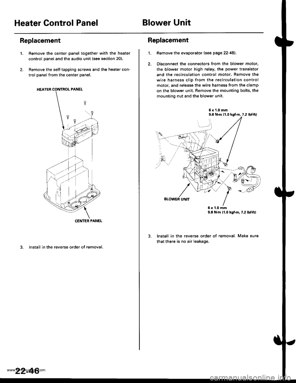
Replacement
'1.Remove the center panel together with the heater
control panel and the audio unit (see section 20).
Remove the self-tapping screws and the heater con-
trol panel from the center panel.
3. lnstall in the reverse order of removal.
CENTER PANEL
22-46
1.
Replacement
Bemove the evaporator (see page 22-48),
Disconnect the connectors from the blower motor,
the blower motor high relay, the power transistor
and the recirculation control motor. Remove the
wire harness clio from the recirculation control
motor, and release the wire harness from the clamp
on the blower unit. Remove the mounting bolts, the
mounting nut and the blower unit.
6x1.0mm9.8 N.m (r,0 kgf.m, 7.2 lbl.ftl
9.E N.m 11.0 kgf.m,7.2lbtftl
lnstall in the reverse order of removal. Make sure
that there is no air leakage.
6x1.0mm
www.emanualpro.com
Page 1141 of 1395
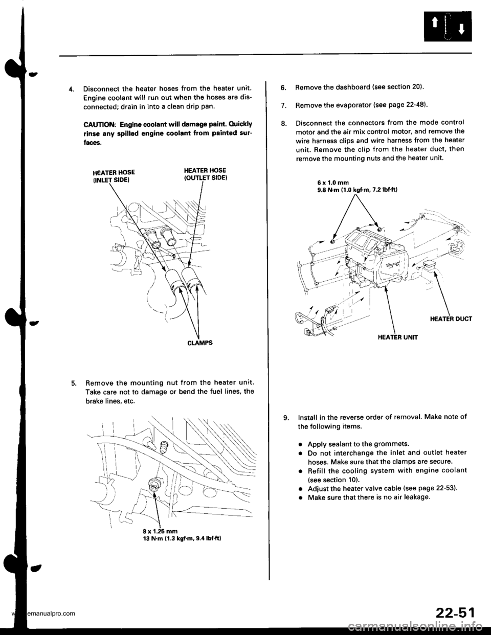
4. Disconnect the heater hoses from the heater unit.
Engine coolant will run out when the hoses are dis-
connected; drain in into a clean drip pan.
CAUTION: Engino coolant will damage p8int. Ouickly
rinse any spill€d engine coolant Itom painted sur-
faces.
HEATER HOSEIOUTLET SIDE)
Remove the mounting nut from the heater unit.
Take care not to damage or bend the fuel lines, the
brake lines. etc.
CLAMPS
13 N.m 11.3 kg{.m,9.4 lbtftl
22-51
7.
ll.
Remove the dashboard (see section 20).
Remove the evaporator (see page 22-48).
Disconnect the connectors from the mode control
motor and the air mix control motor, and remove the
wire harness clips and wire harness from the heater
unit. Remove the clip from the heater duct, then
remove the mounting nuts and the heater unit
6x1.0mm9,8 N.m (1.0 kgt m,7.2lblft)
qInstall in the reverse order of removal. Make note of
the following items.
a
a
a
a
Apply sealant to the grommets.
Do not interchange the inlet and outlet heater
hoses. Make sure that the clamps are secure.
Refill the cooling system with engine coolant
{see section 10).
Adiust the heater valve cable (see page 22-53).
Make sure that there is no air leakage.
HEATER UNIT
www.emanualpro.com
Page 1163 of 1395
Troubleshooting
Tips and Precautions
Bef ore Troubleshootin g
. Check applicable fuses in the appropriate fuse/relay
box.
. Check the battery for damage, state of charge, and
clean. and tight connections.
. Check the alternator belt tension.
CAUTION:
. Do not quick-charge a battery unless the battery
ground cable has been disconnected, otherwise you
will damage the alternator diodes.
. Do not attempt to crank thc engins wilh the battery
ground cable loosely connected or you will severely
damage the wiring.
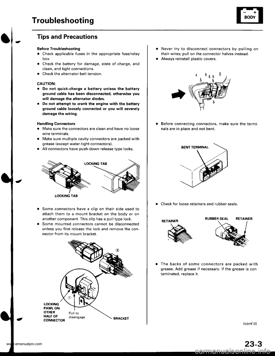
Handling Connestors
. Make sure the connectors are clean and have no loose
wire terminals,
. N4ake sure multiple cavity connectors are packed with
grease (except water-tight connectors).
. All connectors have push-down release type locks.
Some connectors have a clip on their side used to
attach them to a mount bracket on the body or on
another component. This clip has a pull type lock.
Some mounted connectors cannot be disconnected
unless you first release the lock and remove the con-
nector from its mount bracket.
LOCKINGPAWL ONOTHERHALF OFPulltodisengage
LOCKING TAB
CONNECTORBRACKET
Never try to disconnect connectors by pulling on
their wires; pull on the connector halves instead.
Alwavs reinstall olastic covers.
Before connecting connectors, make sure the termi-
nals are in place and not bent.
. Check for loose retainers and rubber seals.
RETAINER
The backs of some connectors are oacked with
grease. Add grease if necessary. lf the grease is con
taminated. reolace it.
{cont'd}
23-3
www.emanualpro.com
Page 1171 of 1395

Gonnector ldentification and Wire Harness Routing
How to ldentity Connectors:
ldentification numbers have been assigned to all connectors, The number is preceded by the letter "C" for connectors.
"G" for ground terminals or "T" for non-ground terminals.
Location
HarnessEngine CompartmsntDashboardOthers lFloor, Door,
8oof, Tailgate)
Starter cableT1, T2 and @
Battery ground cableG1 and O
Engine ground cableT3
Transmission ground cableT4
G3
Engine wire harnessC101 through C137
T101 and T102
G101
Engine compartment ware harnessC201 through C218
G201 and G202
Under-hood ABS fuse/relay box
wire harness
t5ano9
Main wire harnessC301 through C309
C351 through C361
C401 through C447
G401 and G402
Dashboard wire harnessC501 through C524 (C525)
G501
Left side wire harnessC551 through C581
G551, G552 and G553
Right side wire harnessC601 through C605
lnterior wire harnessC701 through C703
Rear bumper wire harnessC641 through C643
Heater sub-harnessC731 through C740
Secondary heated oxygen sensor
sub-harness
C721 through C722
Combination switch sub-harnessC751 through C760
Driver's door wire harnessC661 through C667
Front passenger's door wire harnessC6Tl through C676
Left rear door wire harnessC681 through C684
Right rear door wire harnessC69'l through C694
Rear wire harnessC611 through C520
Tailgate wire harnessC631 through C634
G631
SRS main harnessC801 through C808
G801
High mount brake light sub-harnessC651 through C653
Fuel tank oressure sensor sub-harnessC645 through C647
www.emanualpro.com
Page 1209 of 1395
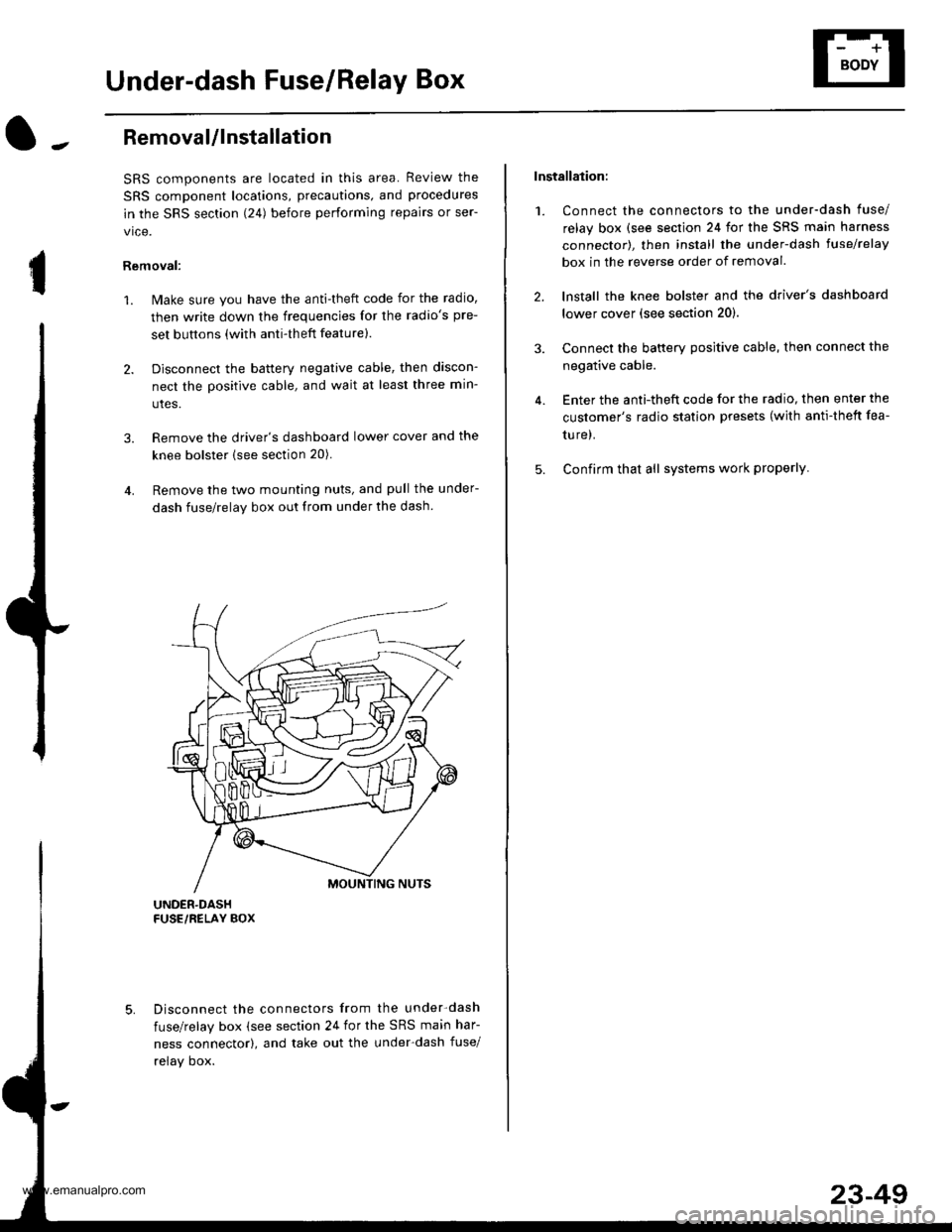
Under-dash Fuse/Relay Box
I
Removal/lnstallation
SRS components are located in this area. Review the
SRS component locations, precautions, and procedures
in the SRS section (241 before performing repairs or ser-
vice.
Removal:
1. Make sure you have the anti-theft code for the radio,
then write down the frequencies for the radio's pre-
set buttons (with anti-theft feature).
2. Disconnect the battery negative cable, then discon-
nect the positive cable, and wait at least three min-
utes.
3. Remove the driver's dashboard lower cover and the
knee bolster (see section 20).
4. Remove the two mounting nuts, and pull the under-
dash fuse/relay box out from under the dash
Disconnect the connectors from the under-dash
fuse/relay box (see section 24 for the SRS main har-
ness connector), and take out the under-dash fuse/
relay oox.
Installation:
1. Connect the connectors to the under-dash fuse/
relay box (see section 24 for the SRS main harness
connector), then install the under-dash lusehelay
box in the reverse order of removal.
2. lnstall the knee bolster and the driver's dashboard
lower cover (see section 20).
3. Connect the battery positive cable, then connect the
negative cable.
4. Enter the anti-theft code for the radio, then enter the
customer's radio station presets (with anti-thett fea-
ture).
5. Confirm that all systems work properly
23-49
www.emanualpro.com
Page 1221 of 1395
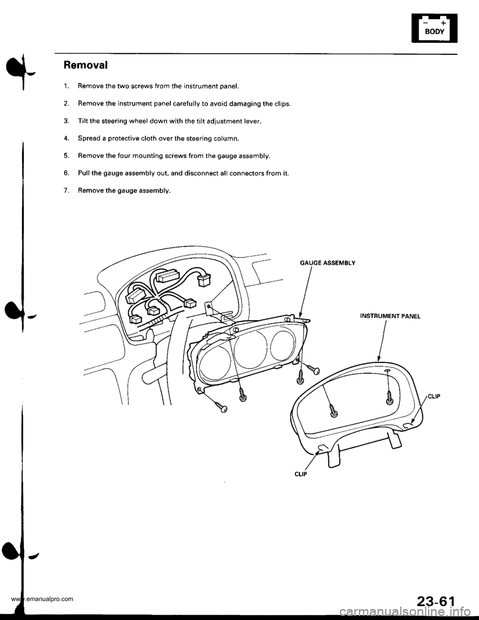
Removal
'1. Remove the two screws from the instrument panel.
2. Remove the instrument panel carefully to avoid damaging the clips.
3. Tilt the steering wheel down with the tilt adjustment lever.
4, Spread a protective cloth over the steering column.
5. Remove the four mounting screws from the gauge assembly.
6. Pullthe gauge assembly out, and disconnect all connectors from it.
7, Remove the gauge assembly.
GAUGE ASSEMELY
INSTRUMENT PANEL
23-61
www.emanualpro.com
Page 1239 of 1395
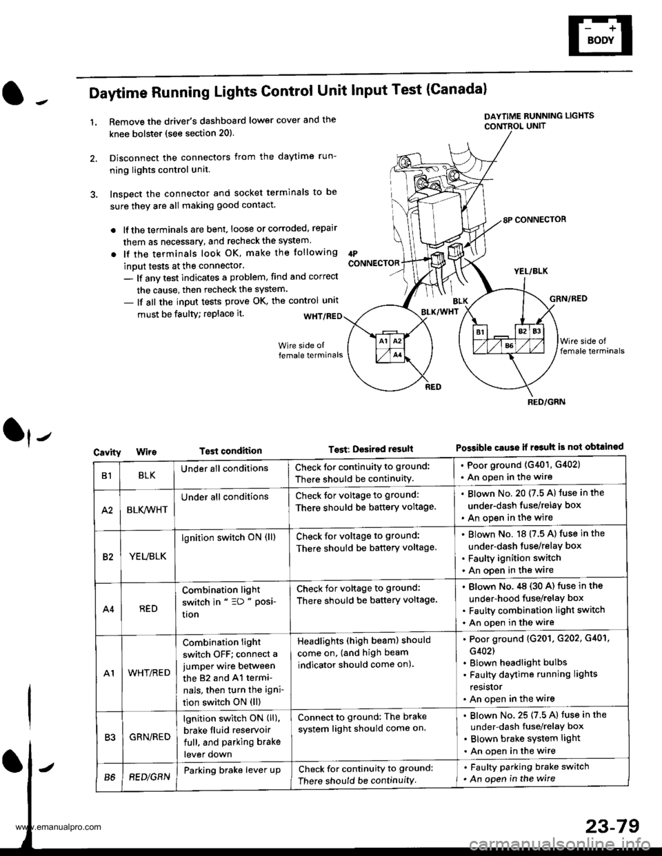
Daytime Running Lights Control Unit Input Test (Canadal
1.Remove the driver's dashboard lower cover and the
knee bolstet (see section 20).
Disconnect the connectors from the daytime run-
ning lights control unit.
Inspect the connector and socket terminals to be
sure they are all making good contact.
lf the terminals are bent, loose or corroded, repair
them as necessary, and recheck the system.
lf the terminals look OK, make the tollowing
inout tests at the connector'
- lf anv test indicates a problem, find and correct
the cause, then recheck the system.
- lf all the input tests prove OK, the control unrt
IPCONNECTOR
must be faulty; replace it.
T€st condition
DAYTIME RUNNING LIGHTS
CONTBOL UNIT
Tost: Desired result
8P CONNECTOR
YEL/BLK
GRN/RED
Possible cause ii r$uh is not obtained
BLK/WHT
Cavity
RED/GRN
B1BLKUnder all conditionsCheck for continuity to ground:
There should be continuity.
. Poor ground (G401, G402)
. An open in the wire
A2BLK,4iVHT
Under all conditionsCheck tor voltage to ground:
There should be battery voltage.
Blown No. 20 (7.5 A) luse in the
under-dash fuse/relay box
An open in the wire
82YEUBLK
lgnition switch oN (ll)Check for voltage to ground:
There should be battery voltage.
Blown No. 18 (7.5 A) fuse in the
under-dash tuse/relay box
Faulty ignition switch
An open in the wire
A4RED
Combination light
switch in " =D " Posi-
uon
Check for voltage to ground:
There should be battery voltage.
Blown No.,tg (30 A) fuse in the
under-hood fuse/relay box
Faulty combination light switch
An open in the wire
A1WHT/RED
Combination light
switch OFF; connect a
jumper wire between
the 82 and 41 termi-
nals, then turn the igni-
tion switch ON (ll)
Headlights (high beam) should
come on, (and high beam
indicator should come on).
Poor ground (G201. G202, G401,
G402)
Blown headlight bulbs
Faulty daytime running lights
resrslor
An open in the wire
R'IGRN/RED
lgnition switch ON (ll),
brake fluid reservoir
full. and parking brake
lever down
Connect to ground: The brake
system light should come on.
Blown No. 25 (7.5 A) fuse in the
under-dash fuse/relaY box
Blown brake system light
An open in the wire
B68EDlGRNParking brake lever upCheck for continuity to ground:
There should be continuity
. Faulty parking brake switch
. An open in the wire
www.emanualpro.com
Page 1244 of 1395
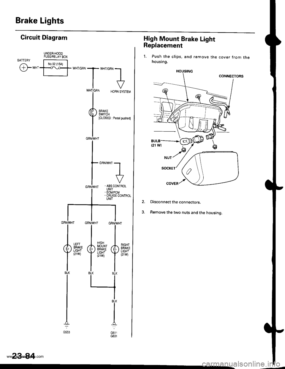
Brake Lights
High Mount Brake Light
Replacement
1. Push the clips, and remove the cover from thehousing.
Disconnect the connectors.
Remove the two nuts and the housing.
2.
HOUSING
Gircuit Diagram
UNDER.HOODFUSE/RELAY BOXBATTENY
/,i | No.s2 {15A) |
\Y*-I=f*-'o*T*'no"l
IV
T:,^-,
HORNSYSTEM
I
i.t53l| *",*"",
GRNA,VHT
GBNMHT -.1
I
I
. ABS CONTFOLUNIT' ECM/PCM. CRUISE CONTROLUNIT
GRNAVHT GRNWH
ll
tl
A[$^Jlr A
Yi,?'il Y
tlBLK BLK
llrl
IBLK
I
I
d
oi,,
RIGHTEFAKELIGHT(21w)
LEFIBFAKELIGHT(2rw)
BLK
G553
23-84
www.emanualpro.com
Page 1247 of 1395
![HONDA CR-V 2000 RD1-RD3 / 1.G Workshop Manual
Turn Signal Switch Test
1.
4.
Remove the drivers dashboard lower cover and the
knee bolster (see section 20).
Remove the steering column covers {see section
17]-.
Disconnect the 4P and 7P connectors HONDA CR-V 2000 RD1-RD3 / 1.G Workshop Manual
Turn Signal Switch Test
1.
4.
Remove the drivers dashboard lower cover and the
knee bolster (see section 20).
Remove the steering column covers {see section
17]-.
Disconnect the 4P and 7P connectors](/img/13/5778/w960_5778-1246.png)
Turn Signal Switch Test
1.
4.
Remove the driver's dashboard lower cover and the
knee bolster (see section 20).
Remove the steering column covers {see section
17]-.
Disconnect the 4P and 7P connectors from the
switch.
Remove the screws, and slide the switch toward the
driver's door.
Check for continuity between the terminals in each
switch position according to the table.
Position
Terminal12
RIGHTo-
Neutral
LEFTo---o
q
tl-
swtTcH
Hazard Warning Switch Test
1. Remove the center panel {see section 20).
2. Remove the two screws, then remove the switch
from the center air vent.
HAZARD
Check for continuitv between the terminals in each
switch position according to the table.
Terminal
t**--\
2357810
OFF(9U(_)
ONo@oooo
lNol us€d)
23-87
www.emanualpro.com