Connectors HONDA CR-V 2000 RD1-RD3 / 1.G Workshop Manual
[x] Cancel search | Manufacturer: HONDA, Model Year: 2000, Model line: CR-V, Model: HONDA CR-V 2000 RD1-RD3 / 1.GPages: 1395, PDF Size: 35.62 MB
Page 1316 of 1395
Precautions/Procedures
)General Precautions
Carefully inspect any SRS part before you install it.
Do not install any part that shows signs of being drop-
ped or improperly handled, such as dents, cracks or
deformation:
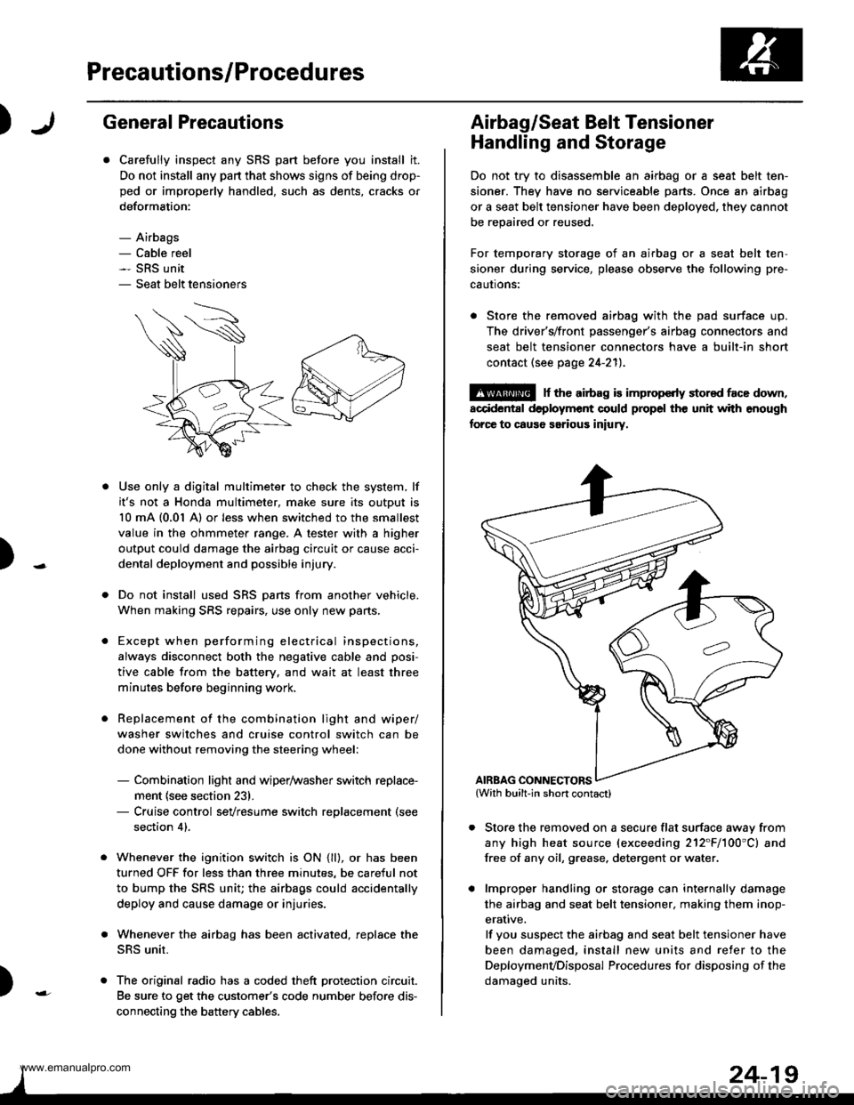
- Airbags- Cable reel- SRS unit- Seat belt tensioners
N
)-
Use only a digital multimeter to check the system, lf
it's not a Honda multimeter, make sure its output is
10 mA (0,01 A) or less when switched to the smallest
value in the ohmmeter range. A tester with a higher
output could damage the airbag circuit or cause acci-
dental deployment and possible injury.
Do not install used SRS Dans from another vehicle,
When making SRS repairs, use only new pans.
Except when performing electrical inspections,
always disconnect both the negative cable and posi-
tive cable from the batterv. and wait at least three
minutes before beginning work.
Replacement of the combination light and wiper/
washer switches and cruise control switch can be
done without removing the steering wheel:
- Combination light and wiper/washer switch replace-
ment {see section 231.- Cruise control sevresume switch replacement (see
section 41.
Whenever the ignition switch is ON {ll}, or has been
turned OFF for less than three minutes, be careful not
to bump the SRS unit; the airbags could accidentally
deploy and cause damage or injuries.
Whenever the airbag has been activated, replace the
SRS unit.
The original radio has a coded theft protection circuit.
Be sure to get the customer's code number before dis-
connecting the battery cables.
)
Airbag/Seat Belt Tensioner
Handling and Storage
Do not try to disassemble an airbag or a seat belt ten-
sioner. They have no serviceable parts. Once an airbag
or a seat belt tensioner have been deployed. they cannot
be repaired or reused.
For temporary storage of an airbag or a seat belt ten-
sioner during service, please observe the following pre-
cautons:
. Store the removed airbag with the pad surface up.
The driver's/front passenger's airbag connectors and
seat belt tensioner connectors have a built-in short
contact (see page 24-211.
@ r th€ airb.g is impropcrty stor€d face down,
accidental deployment could propel the unit with enough
forc€ to caus6 serious iniury,
Store the removed on a secure flat surface awav from
any high heat source (exceeding 212"F/100'C) and
free of any oil, grease. detergent or water.
lmproper handling or storage can internally damage
the airbag and seat belt tensioner. making them inop-
erative.
lf you suspect the airbag and seat belt tensioner have
been damaged, install new units and refer to the
Deploymenvoisposal Procedures for disposing of the
damaoed units.
AIRBAG CONNECTORS
www.emanualpro.com
Page 1317 of 1395
Precautions/Procedures
SRS Unit Precautions
Take extra care when painting or doing body work in
the area below the dashboard. Avoid direct exposure
of the SRS unit or wiring to heat guns, welding, or
spraying equipment.
Disconnect the driver's/front passenger's airbag con-
nectors and seat belt tensioner connectors before
working below the dashboard near the SRS unit.
After any degree of frontal body damage, or after a
collision without airbag deployment, inspect the SRS
unit for physical damage. lf it is dented, cracked, or
detormed, reolace it,
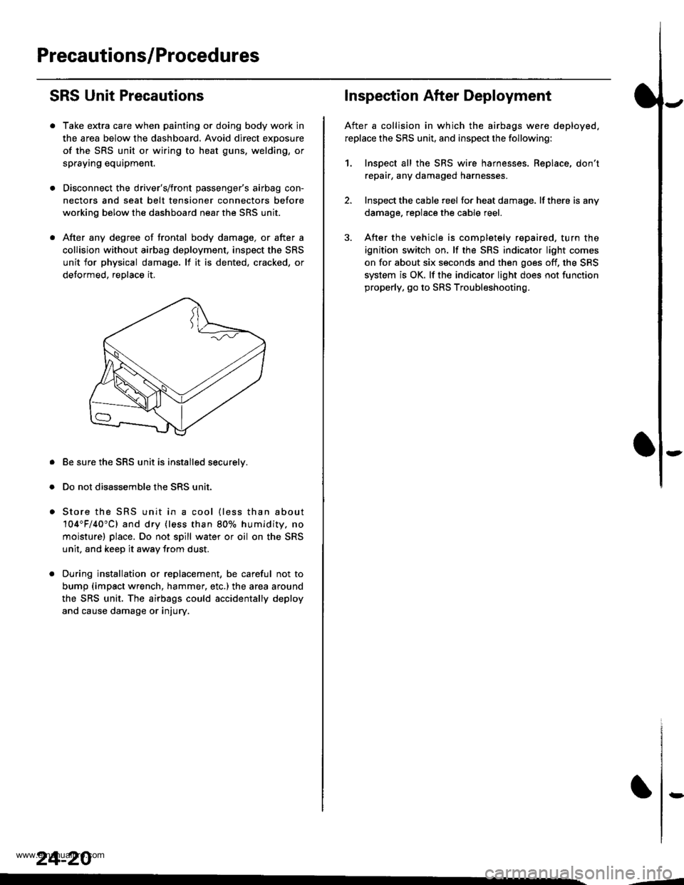
Be sure the SRS unit is installed securelv.
Do not disassemble the SRS unit.
Store the SRS unit in a cool {less than about
104"F/40"C) and dry {less than 80o/o humidity. no
moisture) place. Do not spill water or oil on the SRS
unit, and keep it awav from dust.
During installation or replacement, be careful not to
bump (impact wrench, hammer, etc.) the area a[ound
the SRS unit, The airbags could accidentally deploy
and cause damage or injury.
24-20
,..4
Inspection After Deployment
After a collision in which the airbags were deployed.
replace the SRS unit, and inspect the following:
1. Inspect all the SRS wire harnesses. Replace, don't
repair, any damaged harnesses
2. Inspect the cable reel for heat damage, lf there is any
damage. replace the cable reel.
3. After the vehicle is completely repaired, turn the
ignition switch on. lf the SRS indicator light comes
on for about six seconds and then goes off, the SRS
system is OK. lf the indicator light does not function
properly, go to SRS Troubleshooting.
rD
www.emanualpro.com
Page 1319 of 1395
Precautions/Procedures
Spring-loaded Lock Connectors
Some SRS system connectors have a spring-loaded lock.
Disconnecting
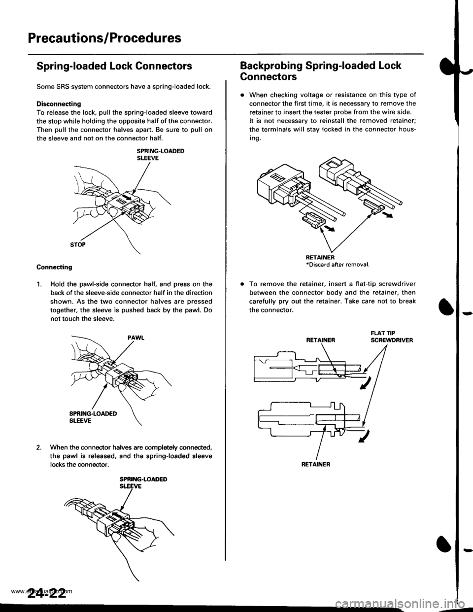
To release the lock, pull the spring-loaded sleeve toward
the stop while holding the opposite halt of the connector.
Then pull the connector halves apart. Be sure to pull on
the sleeve and not on the connector half.
SPRING-LOADEDSLEEVE
Connecting
1. Hold the pawl-side connector hall and press on the
back of the sleeve-side connector half in the direction
shown. As the two connector halves are Dressed
together, the sleeve is pushed back by the pawl. Do
not touch the sleeve.
When the connec-tor halves are completely connected,
the pawl is released. and the spring-loaded sleeve
locks the connector.
SPRING.LOAI'ED
24-22
Backprobing Spring-loaded Lock
Connectors
. When checking voltage or resistance on this type of
connector the first time, it is necessary to remove the
retainer to insert the tester probe from the wire side.
It is not necessary to reinstall the removed retainer;
the terminals will stay locked in the connector hous-
inq.
To remove the retainer, insert a tlat-tip screwdriver
between the connector body and the retainer. then
carefully pry out the retainer. Take care not to break
the connector.
RETAINER*Discard after removal.
RETAINEN
RETAINER
---
www.emanualpro.com
Page 1320 of 1395
)1,Disconnecting the Airbag Gonnectors and the Seat Belt Tensioner Connectors
Before removing the airbag or SRS related devices (the SRS unit, the cable reel and the seat belt tensioner connector), dis-
connecting connectors from related devices, or removing the dashboard or the steering column, disconnect the airbag
connectors and seat belt tensioner connectors to Drevent accidental deployment
@ Turn the ignition switch oFF and disconnect ths nogative cable from the battery, and wait at least ihree
minutes before beginning the tollowing procedures A and B. lprocedure B follows the procedure A.l
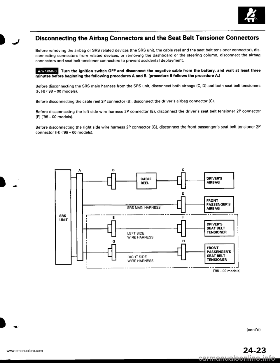
Before disconnecting the SRS main harness from the SRS unit, disconnect both airbags (C, D) and both seat belt tensioners
(F, H) {'98 - 00 models).
Before disconnecting the cable reel 2P connector (B), disconnect the driver's airbag connector (C).
Before disconnecting the left side wire harness 2P connector (E). disconnect the driver's seat belt tensioner 2P connector
(F) ('98 - 00 models).
Before disconnecting the right side wire harness 2P connector (G), disconnect the tront passenger's seat belt tensioner 2P
connector (H) ('98 - 00 models).
SRS MA1N HARNESS
)
i--- E t ----l
i Jl Jl l*",r* I I
LEFT SIDEWIRE HARNESS
){cont'd)
24-23
www.emanualpro.com
Page 1321 of 1395
Precautions/Procedures
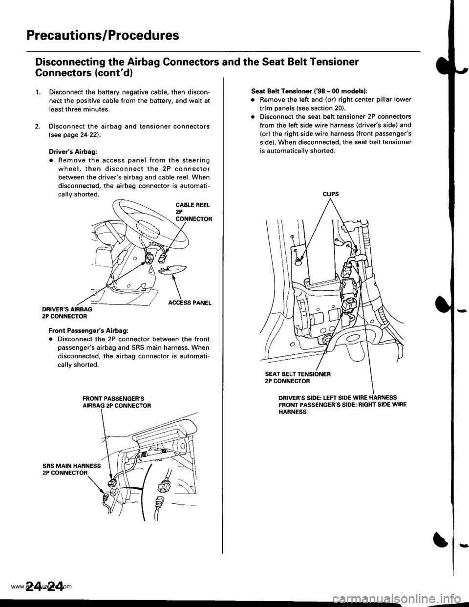
Disconneeting the Airbag Connectors and the Seat Belt Tensioner
Connectors (cont'd)
1.Disconnect the battery negative cable, then discon-
nect the positive cable from the battery. and wait at
least three minutes.
Disconnect the airbag and tensioner connectors
lsee page 24-22).
Driver's Airbag:
. Remove the access panel from the steering
wheel, then disconnect the 2P connector
between the driver's airbag and cable reel. When
disconnected, the airbag connector is automati-
callv shorted.
DRIVER'S AIRBAG2P CONNECTOR
Front Passsng€/sAirtag:
. Disconnect the 2P connector between the front
passenger's airbag and SRS main harness. When
disconnected. the airbag connector is automati-
callY shorted.
24-24
ACCESS PANEL
Seat Bslt Tensioner (38 - 00 modebl:
. Remove the left and (or) right center pillar lower
trim panels (see section 20).
. Disconnect the seat belt tensioner 2P connectors
from the left side wire harness (driver's side) and
(or) the right side wire harness (front passenger's
side). When disconnected. the seat belt tensioner
is automatically shorted.
CLIPS
DRIVER'S SIDE: LEFT SloE WIRE HARNESSFRONT PASSENGER'S SIDE: RIGHT SIDE WIREHARNESS
,--4
www.emanualpro.com
Page 1323 of 1395
Troubleshooting
Self-diagnostic Procedures
The self-diagnostic function of the SRS system allows it to locate the causes of system problems and to store this informa-
tion in memory, For easier troubleshooting, this data can be retrieved via a data link circuit.
. When you turn the ignition switch ON (ll). the SRS indicator will come on. lf it goes off after six seconds, the system is
normal.
. lf there is 8n abnormality, the system locates and defines the problem. stores this information in memory, and turns
the SRS indicator light on. The data will remain in the memory even when the ignition switch is turned off or if the bat-
terv is disconnected.
. When you connect the SCS service connector to the service check connector (2P), and turn the ignition switch ON (ll),
the SRS indicator light will indicate the diagnostic trouble code (DTC) by the number of blinks.
. After reading and recording the DTC, proceed with the troubleshooting forthis code.
Precsutions
. Use only a digital multimeter to check the system. lf it's not a Honda multimeter. make sure its output is 10 mA (0.01 A)
or less when switched to the smallest value in the ohmmeter range. A tester with a higher output could damage the
airbag circuit or cause accidental airbag deployment and possible injury.
. Whenever the ignition switch isON (ll). or has been turned OFF for less than three minutes, be careful nottobumpthe
SRS unit; the airbags could accidentally deploy and cause damage or injuries.
. Before you remove the SRS main harness, disconnect the airbag and tensioner connectors (see page 24-23).
. Make sure the battery is sufficiently charged (see section 23). lf the battery is dead or low, measuring values won't be
correct.
. Do not touch a tester probe to the terminals in the SRS unit or harness connectors, and do not connect the terminals
with a jumper wire. Use only the backprobe set and the SCS service connector.
For backprobing spring-loaded lock type con nectors, .efet to page 24-22.
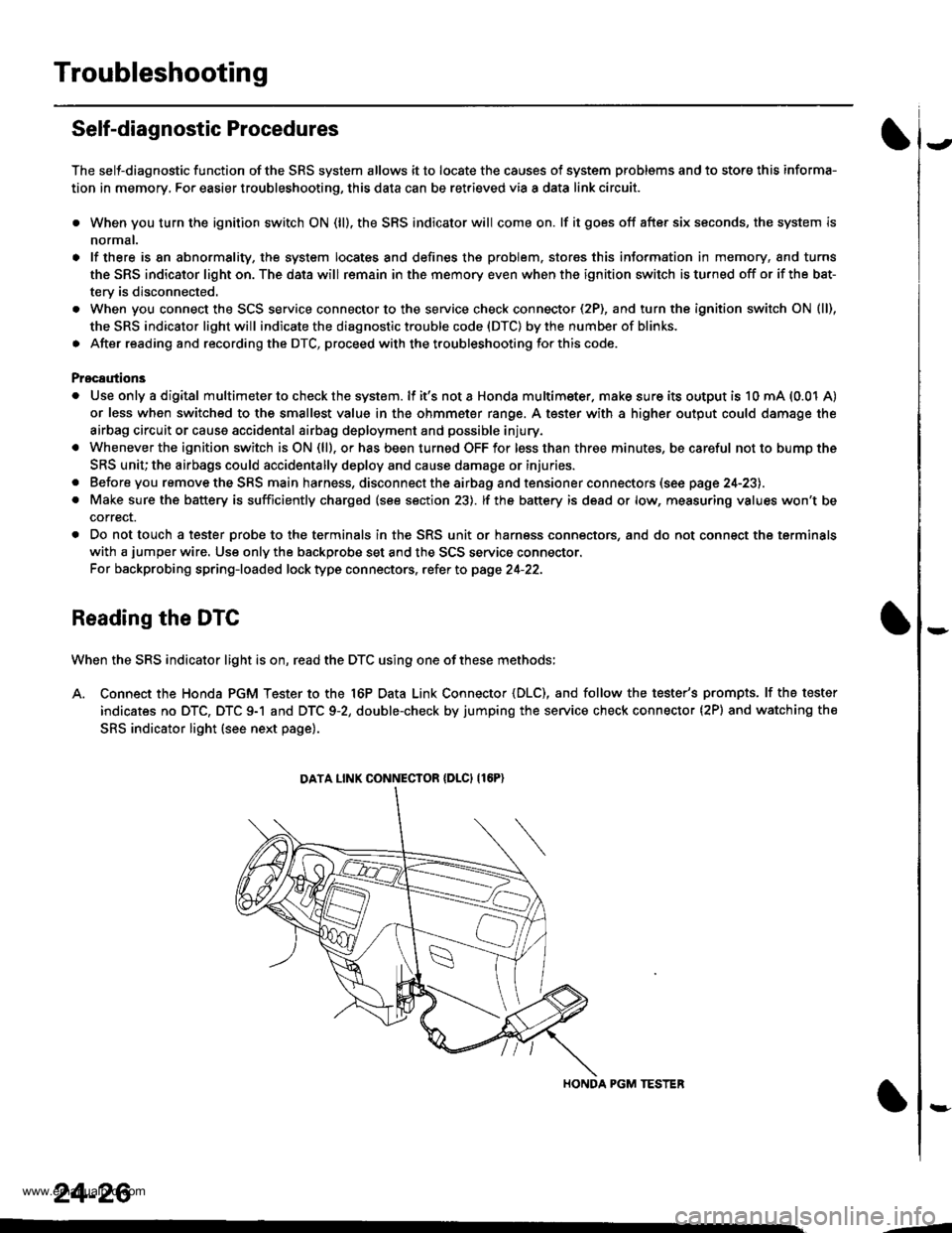
Reading the DTC
When the SRS indicator light is on, read the DTC using one of these methods;
A. Connect the Honda PGM Tester to the 16P Data Link Connector {DLC), and follow the tester's prompts. lf the tester
indicates no DTC, DTC 9-1 and DTC 9-2, double-check by jumping the service check connector (2P) and watching the
SRS indicator light (see next page).
HONDA PGM TESTER
DATA LINK CONNECIOR {DLCI {16P)
24-26
,1
www.emanualpro.com
Page 1333 of 1395
Troubleshooting
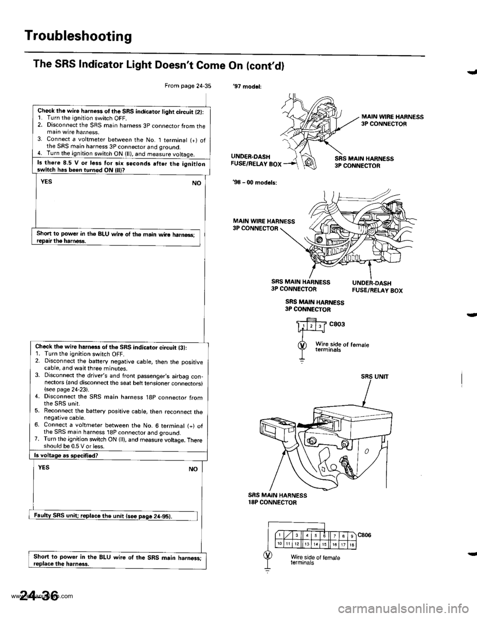
From page 24-35
Check lhe wire harness otthe SRS indicator light circuit l2l:L Turn the ignitjon switch OFF.2. Disconnect the SRS main harness 3p connector from themain wire harness.3. Connect a voltmeter between the No. I terminal (+) ofthe SRS main harness 3P connector and qround.4. Turn the ignition switch ON (ll), and measure voltaqe.
ls there 8.5 V o. less tor six seconds atter the ignitionswitch has been turned ON
Short to power in th€ BLU wire of the main wiro halno3s;
Check th€ wire hahess of th6 SRS indicator ci.cuit {31:1. Turn the ignition switch OFF.2. Disconnect the battery negative cable, then the positivecable, and wait three minutes.3. Disconnect the driver's and front passenger,s airbag con-nectors {and disconnect the seat belt tensioner connectors}(see page 24-23).4. Disconnect the SRS main harness 18p connector from
5. Reconnect the battery positive cable, then reconnect thenegative cable.6. Connect a voltmeter between the No. 6 terminal (+) ofthe SRS main harness 'l8P connector and ground.7. Turn the ignition switch ON (ll), and measure voltage. Thereshould be 0.5 V or less.
Short to power in the BLU wire oI the SRS main harngas;
The SRS Indicator Light Doesn't Come On (cont,dl
'97 modol:
J
MAIN WIRE HARNESS3P CONNECTOR
UNDER.DASHFUSE/RELAY BOX
'98 - 00 models:
SRS MAIN HARN€SS3P CONNECTOR
MAIN WIRE HARNESS3P CONNECTOR
SRS MAIN HARNESS3P CONNECTOR
SRS MAIN HARNESS3P COI{NECTOB
FUSE/RELAY BOX
c803
SRS MAIN HARNESS18P CONNECTOR
24-36
www.emanualpro.com
Page 1338 of 1395
)
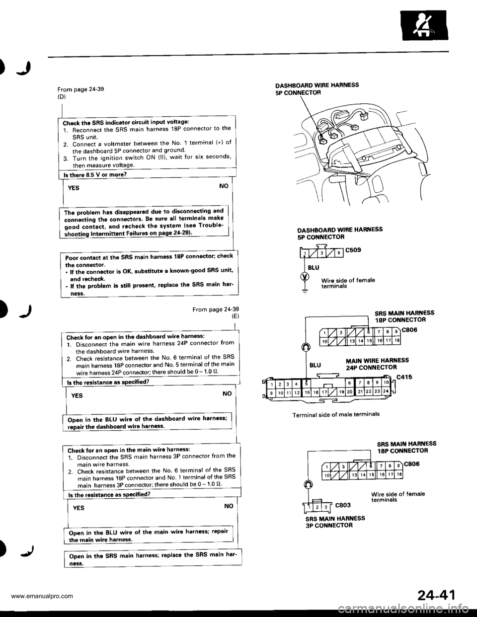
From page 24-39(D)
DASHBOARD wlRE hARNESS
5P CONNECTON
DASHBOARO WIRE HARI{ESS
5P CONI{EC'OR
)From page 24-39iE)
c509
Terminal side of male lerminals
SRS MAIN HABN€SS3P CONNECTOR
)
Check the SRS indicator circuit input voltage:
1. Reconnect the SRS main harness 18P connector to the
SRS unit2. Connect a voltmeter between the No 1 terminal (+) of
the dashboard 5P connector and ground.
3. Turn the ignition switch ON (ll), wait for six seconds,
then measure voltage
fs there 8.5 V or more? -
YESNO
The oroblem hts disappoared due to disconnocting and
connecting the connectors. Be 3ure all terminals make
good contact, and rocheck the system {see Trouble'
shooting Intermittent Failur6 on pagg 2'l-281'
Pool contacl at the SRS main harness 18P connector; check
the connector.. lf the connoctor is OK. aubstituta a known-good SRS unit,
and recheck.. ll the problem is still present, replaco the SRS main h'r-
ness.
Check for an oPen in the dashboard wire hatn8s:
1. Disconnect the main wire harness 24P connector Irom
the dashboard wire harness
2. Check resistance between the No. 6 terminal of the SRS
main hamess 18P connector and No 5 terminal otthe main
wire harness 24P connector; there should be 0- 1 0 O
15 the resistance.s specified?
YESNO
ODen in the BLU wire ot the dashboard wit6 harness;
rep.ir the dashboald wite harness.
Check for an open in the main wirc harness:'1. Disconnect the SRS main harness 3P connector from the
main wire harness,2. Check resistance between the No. 6 terminal of the SRS
main harness 18P connector and No 1 terminal ofthe SRS
main harness 3P connector;there should be 0 - 1 0 u
|3 lhe re3istance as sPecifiod?
YESNO
Oo€n in the BLU wire ol the main wire harness; rcpair
tha main wire harness
Op€n in the SRS main harn4s; replace the SRS msin har'
no3s.
24-41
www.emanualpro.com
Page 1339 of 1395
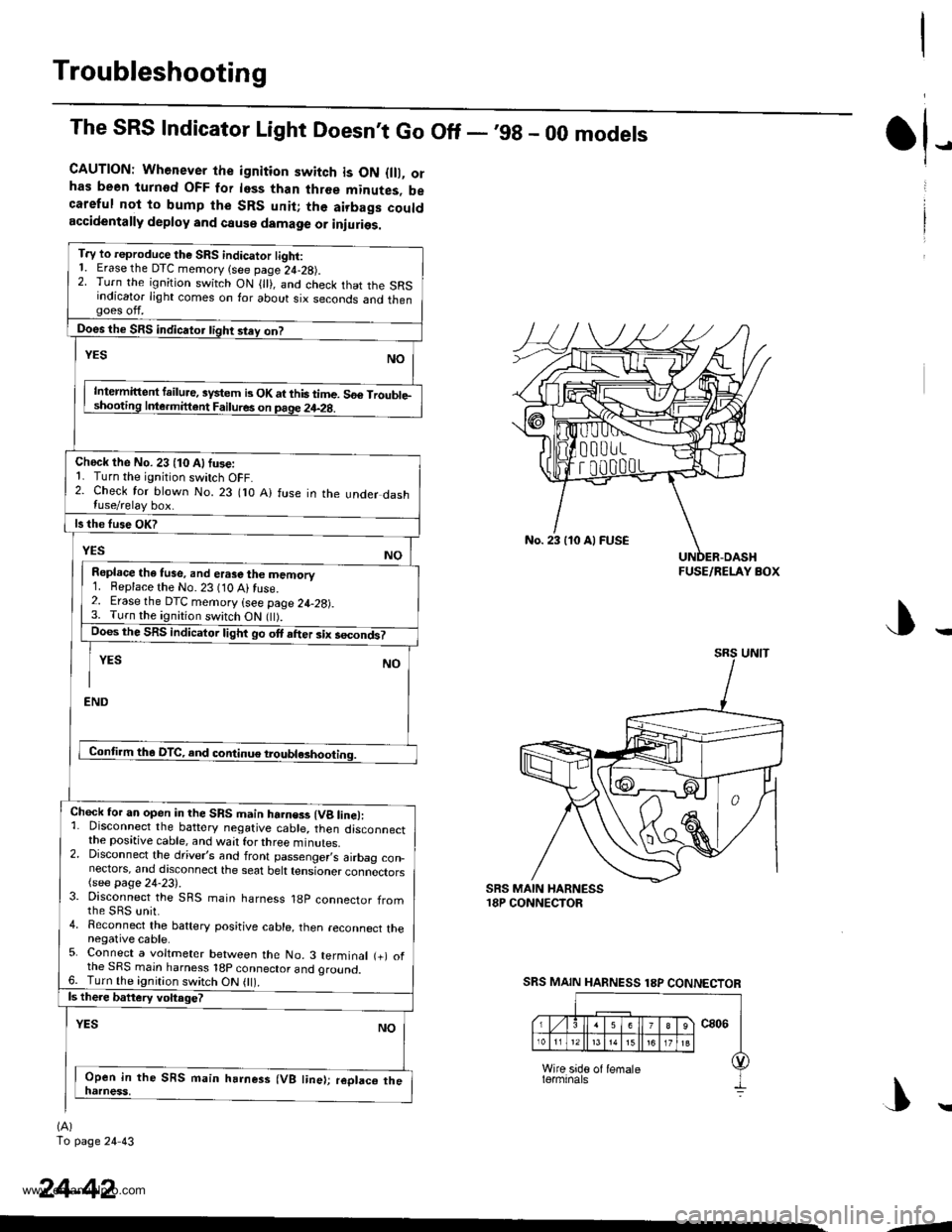
Troubleshooting
The SRS Indicator Light Doesnt Go Off - ,99 - 00 models
CAUTION: Whenever the ignition switch is ON {lll, orhas been turnod OFF for less than three minutes, becareful not to bump the SRS unit; the airbags couldaccidentally deploy and cause damage or iniuries.
T.y to reproduce the SRS indicator tight:1. Erase the DTC memory (see page 24-28).2. Turn the ignition switch ON { }, and check that the SRSindicator light comes on for about six seconds and thengoes off.
Does the SRS indicator tight stey on?
NOYES
Intermittent failure, system b OK at this time. 56€ Trouble-shooting Inle.mittent Failures on page 24-2g.
Check the No. 23 (10 Alfuse:1. Turn the ignition switch OFF.2. Check for blown No. 23 flO A) fuse in the under dashluse/relay box.
ls the fuse OK?
YESNO
Repl.ce the tuse, and erase the memory1. Beplace the No. 23 (10 Ai fuse.2. Erase the DTC memory (see page 24-28).3. Turn the ignition switch ON flt).Does the SRS indicator light go ott after six secondt
YES NO
I
END
Conti.m tha DTC, and continue troubl*hooting.
Chock for an open in the SRS main harness (Vg line):1. Disconnect the battery negative cable, then disconnectthe positive cable, and wait for three minutes.2. Disconnect the driver,s and front passenger,s airbag con_nectors, and discoonect the seat belt tensioner connectors(see page 24-23).3. Disconnect the SRS main harness 18p connector fromthe sRs unit.4. Reconnect the baftery positive cable, then reconnect thenegative cable.5. Connect a voltmeter between the No. 3 terminal (+) ofthe SRS main harness 18p connector and oround.6. Turn the ignition switch ON 0l).ls there battery voltage?
YESNO
Open in the SRS main harness (VB line); replaco thenatness,
(A)
To page 24 43
tl-
24-42
No. 23 110 Al FUSE
FUSE/RELAY BOX
SRS MAIN HARNESS 18P CONNECTOR
|\
-1
www.emanualpro.com
Page 1343 of 1395
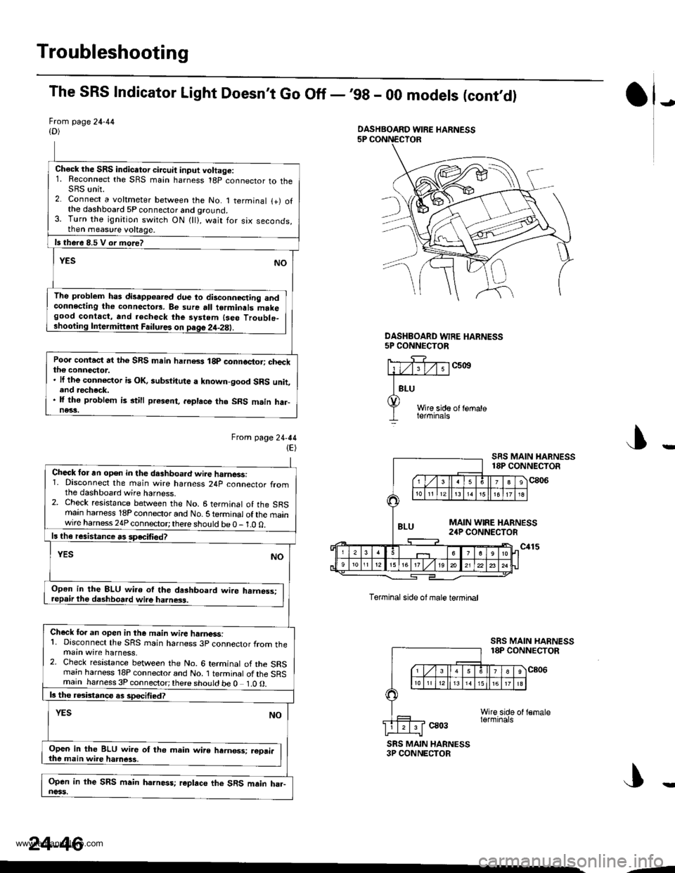
Troubleshooting
The SRS Indicator Light Doesn't Go Off -,99 - 00 models (cont,d)
Frcm page 24-44{D)
Ch€ck the SRS indicator circuit input voltage:1. Reconnect the SRS main harness 18p connector to theSRS unit.2. Connect a voltmeter between the No. 1 terminal {+) ofthe dashboard 5P connector and ground.3. Turn the ignition switch ON {ll}, wait for six seconds,then measure voltage.
ls there 8.5 V or more?
YESNO
The problem has disapp€ared due to disconnecting andconnecting tho connectors. Be sure all terminals makegood contact, and .echeck the system {seo Troublo_shooting Intermiftent Failures on page 2it-2E).
Poo. contact at the SRS main harn8s 18p connector; checkthe connector.. lf the connoctor is OK, aubstitute a known-good SRS unit,end recheck.. lf the problem is still present, .6place tho SRS m.in har-ne33.
Ftom lage24-44(E)
J)
DASHEOARD WFE HARNESS5P CONNECTOR
c5ott
Wire side of lemaleterminals
J
Torminal side ol male termtnal
ca03
SRS MAIN HARNESS18P CONNECTOR
c806
SRS MAIN HARNESS3P CONNECTOR
DASHBOARD WIRE HARNESS
Check for an open in the dashboa.d wire harnessi1. Disconnect the main wire harness 24p connector fromthe dashboard wire harness.2. Check resistance between the No. 6 terminal of the SRSmain harness 18P connector and No. S te.minal of the mainwire harness 24P connector; there should be 0 - 1.0 0.
ls th€ resistance rs speciliedT
YESNO
Open in the 8LU wi.o ol the dashboard wire hrmess:repair the dashboard wire ha.ness.
Check fo. an open in the m.in wire hamess:1. Disconnect the SRS rnain harness 3p connector from themain wire harness,2. Check resistance between the No. 6 terminal of the SRSrnain harness 18P connector and No. 1 terminal of the SRSmain harness 3P connector;there should be 0 1.0O.
b the rGbtanco as sDecified?
NOYES
Open in the BLU wir6 of th6 main wire hernos3; reori.the main wire hamess,
Open in the SRS main harness; r€place the SRS main ha.-noss.
24-46
--
www.emanualpro.com