wire HONDA CR-V 2000 RD1-RD3 / 1.G Workshop Manual
[x] Cancel search | Manufacturer: HONDA, Model Year: 2000, Model line: CR-V, Model: HONDA CR-V 2000 RD1-RD3 / 1.GPages: 1395, PDF Size: 35.62 MB
Page 713 of 1395
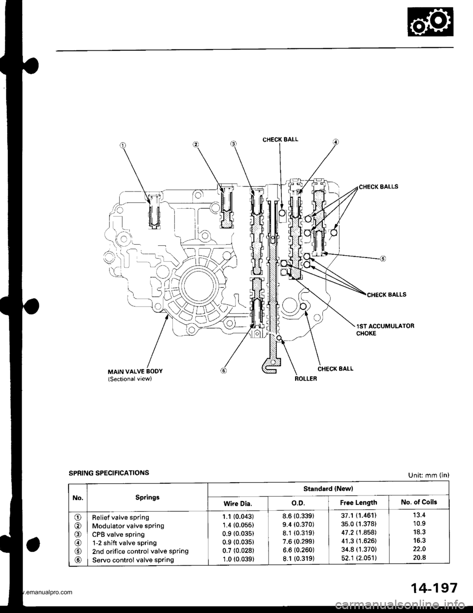
CHECK BALL
i)L)
lo
CHECK BALLS
lST ACCUMULATORCHOKE
CHECK EALLMAIN VALVE BODY(Sectionalview)
SPRING SPECIFICATIONSUnit: mm (in)
No.Springs
Standard {New)
Wire Dia.o.D.Froe LengthNo. of Coils
o
@
@
@
Relief valve spring
Modulator valve spring
CPB valve spring
1-2 shift valve spring
2nd orifice control valve spring
Servo control valve sPring
1.1 (0.043)
1.4 (0.055)
0.9 (0.03s)
0.9 (0.035)
0.7 (0.028)
1.0 t0.039)
8.6 (0.339)
9.4 (0.370)
8.1 (0.319)
7.6 (0.299)
6.6 (0.260)
8.1 {0.319)
37.1 (1.461)
35.0 (1.3781
41 .2 \1 .8581
41.3 (1.626)
34.8 (1.370)
52.1 (2.051)
'13.4
10.9
20.8
14-197
www.emanualpro.com
Page 714 of 1395
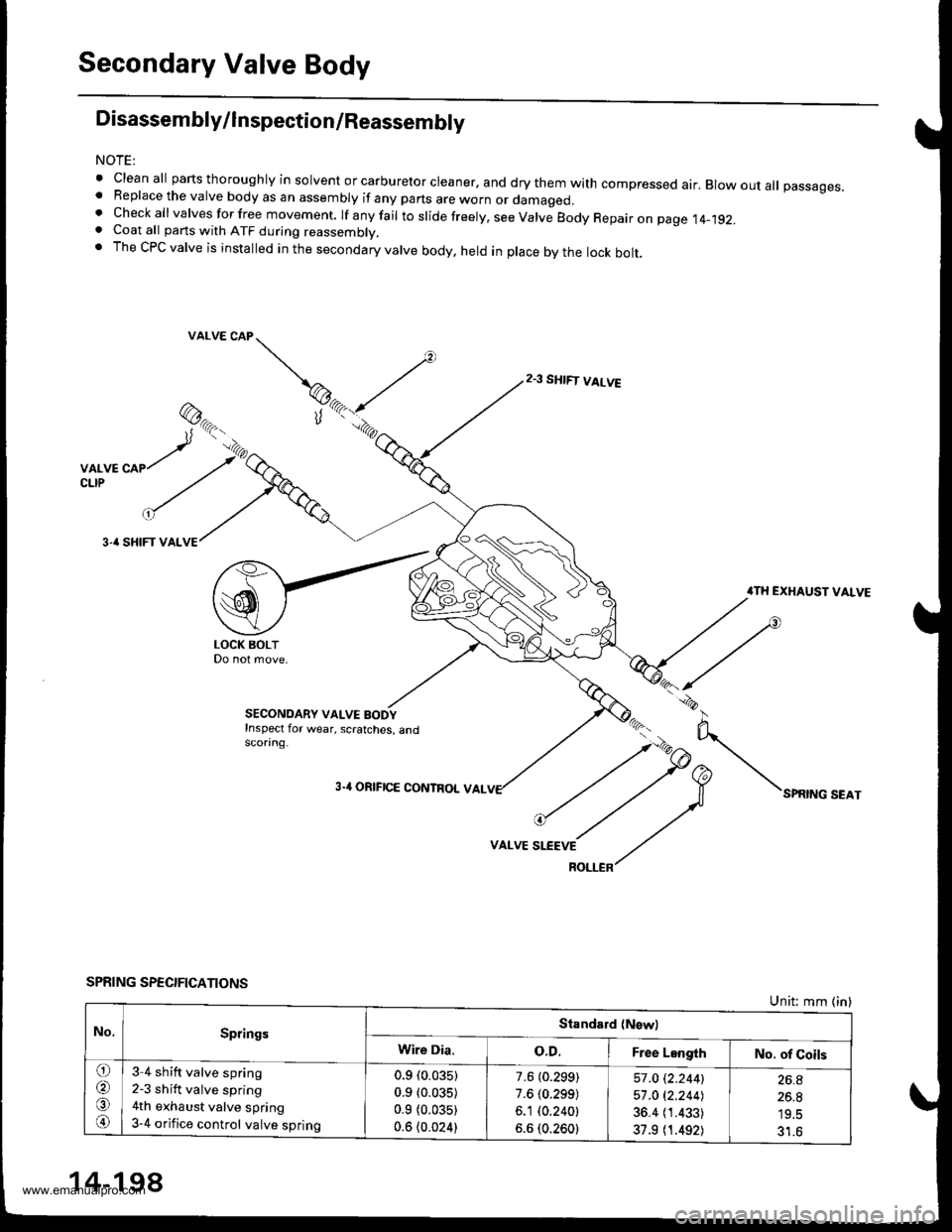
Secondary Valve Body
Disassembly/lnspection/Reassembly
NOTE:
' clean all parts thoroughly in solvent or carburetor cleaner. and dry them with compressed air. Blow out aU passages,. Replace the valve body as an assembly if any parts are worn or damaged.t check all valves for free movement. rf anyfair to sride freery. see varve Body Repair on page 14-192.. Coat all parts with ATF during reassembly.. The CPC valve is installed in the secondary valve body, held in place by the lock bolt.
@,.-.t'tr.,
,rr'^'//u
"/ ./
3-' SHIFT VALVE
VALVE CAP
SPRING SPEC!FICATIONS
2.3 SHIFT VALVE
VALVE SLEEVE
ROLLER
ilTH EXHAUST VALVE
N"*,"o"*,
Unit: mm (in)
t*-1
SECONOARY VALVE BODYInspect for wear, scratches, andscorang.
3.4 ORIFICE CONTROL VAL
No.SpringsStandald {Nswl
Wire Dia.o.D.Free LengthNo. of Coils
o
@
o
@
3 4 shift valve spring
2-3 shift valve spring
4th exhaust valve spring
3-4 orifice control valve spring
0.9 (0.035)
0.9 (0.035)
0.9 {0.035)
0.6 {0.024}
7.6 (0.299)
7.6 (0.299)
6.1 (0.240t
6.6 (0.2601
57 .O i.2.2441
57 .O 12.244J
36.4 (1.433)
37.9 (1.492)
26.A
26.8
19.5
31.6
14-198
www.emanualpro.com
Page 715 of 1395
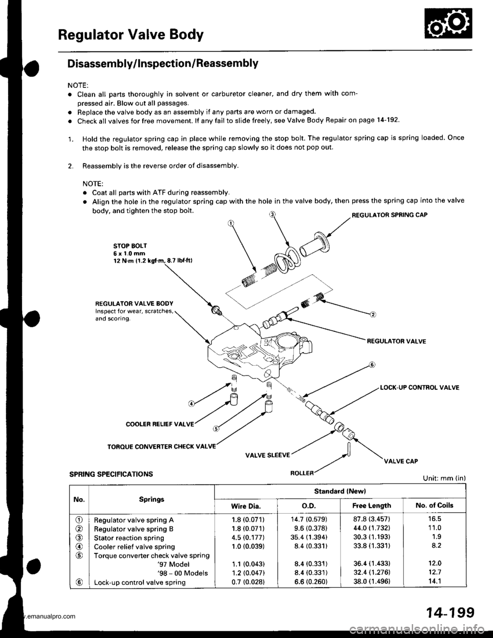
Regulator Valve Body
Disassembly/lnspection/Reassembly
NOTE:
o Clean all parts thoroughly in solvent or carburetor cleaner, and dry them with com-
pressed air. Blow out all passages.
. Replace the valve body as an assembly if any parts are worn or damaged.
. Checkall valvesforfree movement. lf anyfail toslidefreely, see Valve Body Repair on page l4-192.
'1. Hold the regulator spring cap in place while removing the stop bolt. The regulator spring cap is spring loaded Once
the stop bolt is removed, release the spring cap slowly so it does not pop out.
2. Reassembly is the reverse order of disassembly.
NOTE:
. Coat all parts with ATF during reassembly.
. Align the hole in the regulator spring cap with the hole in the valve body, thenpress the spring cap into the valve
REGULATOR SPSING CAPbody, and tighten the stop bolt.
STOP BOLT6x1.0mm12 N.m 11.28.? tbt.fil
REGULATOR VALVE BODYlnspect for wear, scratches,ano scoflng.
REGULATOR VALVE
No,SpringsStandard {New}
wire Dia.o.D.F ee LengthNo. ot Coils
o
@
@,6
a,
Regulator valve spring A
Regulator valve spring B
Stator reaction spring
Cooler relief valve spring
Torque converter check valve spring'97 Model'98 - 00 Models
Lock-up control valve spring
1.8 (0.071)
1.8 (0.071)
4.5 (0.177)
1.0 {0.039)
1.1 (0.043)
1.2lO.O47l
0.7 t0.028)
14.7 (0.579)
9.6 (0.378)
35.4 (1.394)
8.4 {0.331)
8.4 (0.331)
8.4 (0.331)
6.6 (0.260)
87.8 (3.457)
44.0 t1.7321
30.3 (1.193)
33.8 (1.331)
36.4 (1.433)
32.4 11.2761
38.0 (1.496)
'11.0
1.9
't2.0
12.7
14.'l
14-199
www.emanualpro.com
Page 716 of 1395
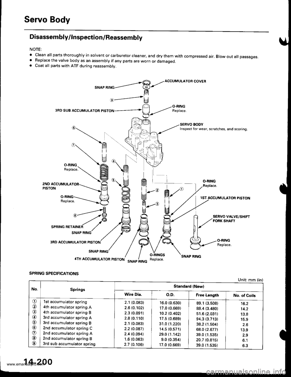
Servo Body
Disassembly/lnspection/Reassembly
NOTE:
' cleanall parts thoro ugh ly in solvent or ca rbu retor clea ner, a nd dry them with compressed air, Blow out all passages.. Replace the valve body as an assembly if any parts are worn or damaged.. Coat all parts with ATF during reassembly.
ACCUMULATOR COVER
3RO SUB ACCUMULATOR
O-RINGFeplace.
SERVOFORK S
fi,
il
g
1ST ACCUMULATOR PISTON
Replace.
RVO VAL\IRK SHAFT
O.RING
VE/SHIFT
3RD ACCUMULATOR
SPRING SPECIFICATIONS
\_)
SNAP RING
SNAP RING
Unit: mm {in)
@"- -tP
-.t l@SPR|NG RETATNER ,/
No.SpringsStandard lNewl
Wire Dia,o.D.Free LongthNo. of Coil3
o
@J6
@.A
\o,
o
@
@
1st accumuiator spring
4th accumulator spring A
4th accumulator spring B
3rd accumulator spring A
3rd accumulator spring B
2nd accumulator spring C2nd accumulator spring A2nd accumulator spring B
3rd sub accumulator spring
2.1 (0.083)
2.6 {0.102)
2.3 (0.091)
2.8 (0.110)
2.1 (0.083)
2.2 (0.087l-
2.4 (0.094)
r.6 (0.063)
2.7 {0.106)
16.0 (0.6301
17.0 (0.669)'t0.2 t0.402]�
17.5 (0.689)
31.0 (1.220)
14.5 {0.571)
29.0 11.1421
9.0 (0.354)
17.0 (0.669)
89.r (3.508)
88.4 (3.480)
51.6 (2.031)
94.3 (3.713)
38.2 (1.504)
68.0 {2.677)
39.0 fi.535)
20.7 (0.815)
39.0 (1.535)
14.2
13.8
15.9
2.6
13.9
2.9
o.l
6.3
14-200
www.emanualpro.com
Page 717 of 1395
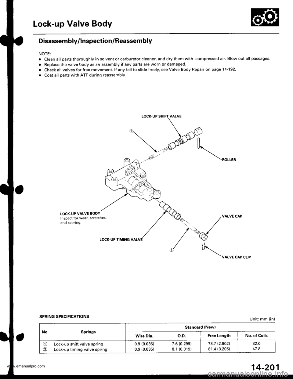
Lock-up Valve Body
Disassembly/lnspection/Reassem bly
NOTE:
. Clean all parts thoroughly in solvent or carburetor cleaner, and dry them with compressed air. Blow out all passages.
. Replace the valve body as an assembly if any parts are worn or damaged.
. Checkall valvesforfree movement. lf anyfailto slide freely, seeValve Body Repairon page 14-192.
. Coat all parts with ATF during reassembly.
LOCK.UP SHIFT VALVE
\/'
\-.xlO
@-tr
, ^ ,As'. \"o...*
LOCK-UP VALVE EODY
Inspect lor wear, scratches,
and scoring.
VALVE CAP
\uo.*"or".,,
LOCK-UP TIMING VAL
SPRING SPECIFICATIONSUnit: mm (in)
No.SpringsStandard lNewl
Wire Dia.o.D.Fle€ LengthNo. of Coils
O(Lock up shift valve spring
Lock-up timing valve spring
0.9 (0.035)
0.9 (0.035)
7.6 (0.299)
8.1 (0.319)
73.1 t2.902),
81.4 (3.205)
32.0
47 .8
14-201
www.emanualpro.com
Page 780 of 1395
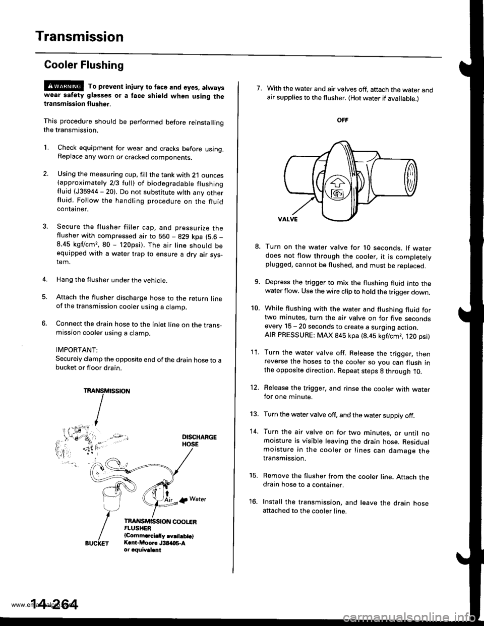
Transmission
Cooler Flushing
@@ To prevent in;ury to face and eyos, atwayswear safety glasses ot a face shield when using thetlansmission flusher.
This procedure should be performed before reinstallingthe transmission.
2.
LCheck equipment for wear and cracks before using.Replace any worn or cracked components.
Using the measuring cup. fill the tank with 21 ounces{approximately 213 lull) ol biodegradable flushingfluid (J35944 - 20). Do not substitute with any otherfluid. Follow the handling procedure on the fluidcontaaner.
Secure the flusher filler cap, and pressurize theflusher with compressed air to 550 - 829 kpa (5.6 _
8.45 kgf/cm,, 80 - 120psi). The air line should beequipped with a water trap to ensure a dry air sys-tem.
Hang the flusher under the vehicle.
Attach the flusher discharge hose to the return lineof the transmission cooler using a clamp.
Connect the drain hose to the inlet line on the trans-mission cooler using a clamp.
IMPORTANT:
Securely clamp the opposite end ofthe drain hose to abucket or floor drain.
DISCHARGEHOSE
tAirlp Water
TnAI{SrfiSStoN coot"€RFLUSHER{Comm.rcidly.v.il.bt.lK.r -Moor. J38,t{15.Aor aquival.nt
5.
14-264
7. With the water and air valves off, attach the water andair supplies to the flusher. (Hot water if available.)
10.
8.
1'�I.
Turn on the water valve for 1O seconds. lf waterdoes not flow through the cooler, it is completelyplugged, cannot be flushed, and must be replaced.
Depress the trigger to mix the flushing fluid into thewater flow. Use the wire clip to hold the trigger down.
While flushing with the water and flushing fluid fortwo minutes, turn the air valve on for five secondsevery 15 - 20 seconds to create a surging action.AIR PRESSURE: MAX 845 kpa (8.45 kgf/cmr, t20 psi)
Turn the water valve off. Release the trigger, thenreverse the hoses to the cooler so you can flush inthe opposite direction. Repeat steps 8 through 10.
Release the trigger, and rinse the cooler with wate.for one minute.
Turn the water valve off, and the water supply off.
Turn the air valve on for two minutes, or until nomoisture is visible leaving the drain hose. Residualmoisture in the cooler or lines can damage thetransmission.
Remove the flusher from the cooler line. Attach thedrain hose to a container.
Install the transmission, and leave the drain hoseattached to the cooler line.
12.
13.
14.
to.
www.emanualpro.com
Page 785 of 1395
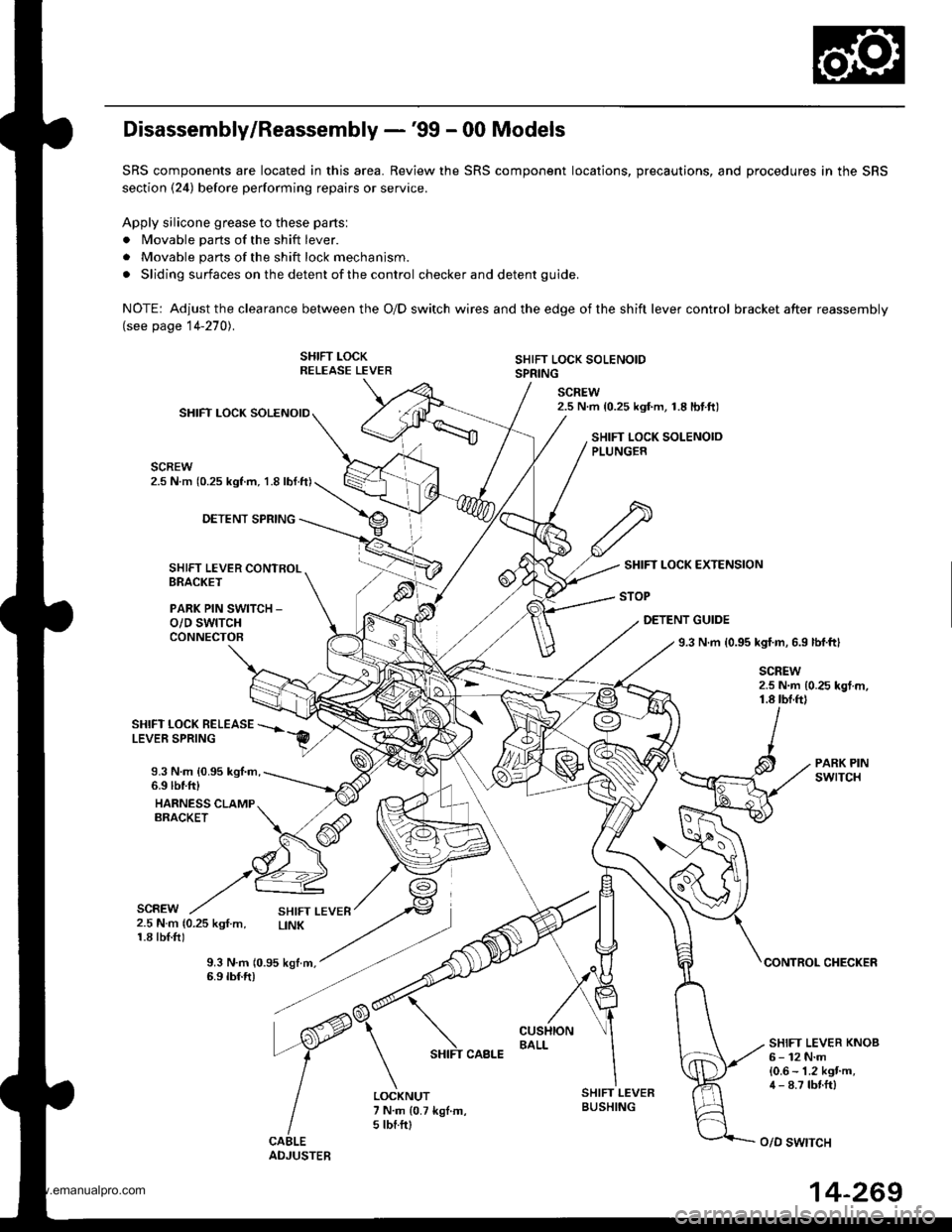
Disassembly/Reassembly -'99 - 00 Models
SRS components are located in this area. Review the SRS component locations, precautions, and procedures in the SRS
section (24) before performing repairs or service.
Apply silicone grease to these parts:
. Movable parts of the shift lever.
. Movable parts of the shift lock mechanism.
. Sliding surfaces on the detent of the control checker and detent guide.
NOTE: Adjustthe clearance between the O/D switch wires and the edge ofthe shift lever control bracket after reassembly(see page 14-270).
SHIFT LOCKRELEASE LEVERSHIFT LOCK SOLENOIDSPRING
SCREW2.5 N.m {0.25 kgf.m, 1.8lbtft)SHIFT LOCK SOLENOID
SCREW2.5 N.m (0.25 kgl.m, 1.8 lbl.ft)
SHIFT LOCK SOLENOIOPLUNGER
DETENT SPRING
SHIFT LEVER CONTROLBRACKET
PARK PIN SWITCH _
o/D swtTcHCONNECTOB
SHIFT LOCK EXTENSION
STOP
DETENT GUIDE
9.3 N.m {0.95 kgf.m, 6.9 lbl.ftl
SCREW2.5 N.m {0.25 kgt m,1.8 tbf.ftl
SHIFT LOCK BELEASELEVER SPRING
9.3 N.m {0.95 kgl.m,6.9 lbtfr)
HARNESS CLAMPERACKET
PARK PINswrTcH
SCREW2.5 N.m {0.25 kgf.m,1.8 tbl.f0
9.3 N.m 10.95 kgtm,6.9 tbf.ft)CONTROL CHECKER
SHIFT LEVER KNOB6- 12 N.m{0.6 - 1.2 kgt'm,4 - 8.7 tbnft)LOCKNUT7 N.m {0.7 kgl.m,5 tbf.ftl
SHIFT LEVERBUSHING
o/D swtTcH
14-269
www.emanualpro.com
Page 786 of 1395
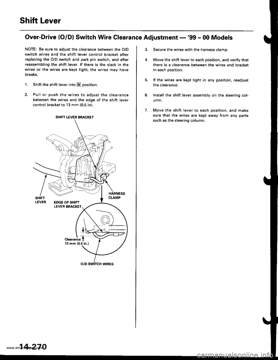
Shift Lever
Over-Drive (O/Dl Switch Wire Clearance Adjustment -'99 - 00 Models
NOTE: Be sure to adjust the clearance between the O/D
switch wires and the shift lever control bracket after
replacing the O/D switch and park pin switch, and after
reassembling the shift lever. lf there is the slack in the
wires or the wires are kept tight, the wires may have
Dreaks.
1. Shift the shift lever into E positron.
2. Pull or push the wires to adjust the clearance
between the wires and the edge of the shift lever
control bracket to 13 mm (0.5 in).
SHIFT LEVER BRACKET
14-270
7.
Secure the wires with the harness clamp.
Move the shift lever to each position, and verify that
there is a clearance between the wires and bracket
in each position.
lf the wires are kept tight in any position, read.iust
the clearance.
Install the shift lever assembly on the steering col-
umn.
Move the shift lever to each position, and make
sure that the wires are kept away from any parts
such as the steering column.
www.emanualpro.com
Page 787 of 1395
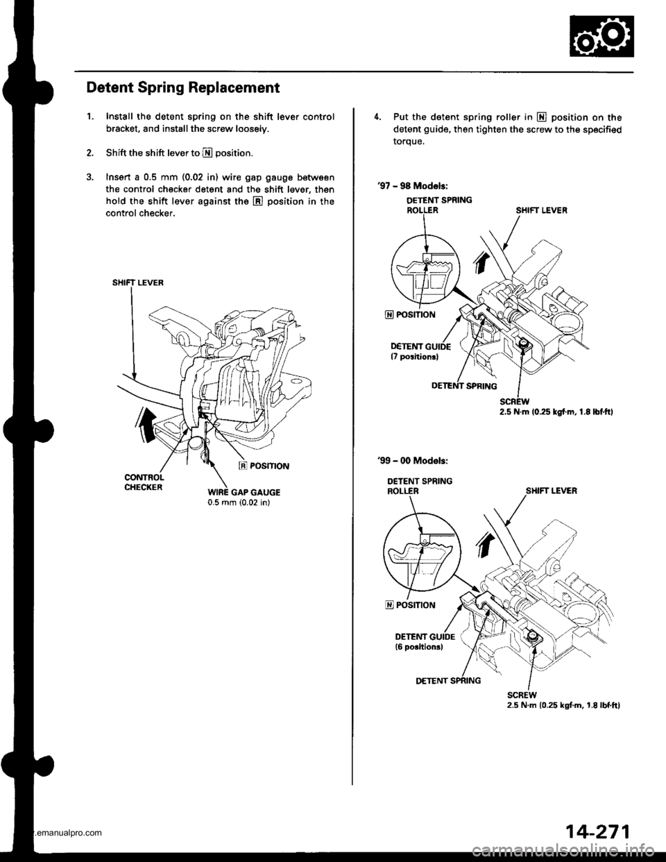
Detent Spring Replacement
1.Install the detent spring on th€ shift lever control
bracket, and installthe screw loosely.
Shift the shift lever to E position.
lnssrt a 0.5 mm (0.02 in) wire gap gauge between
the control chocker detent and the shift lever, then
hold the shift lever against the El position in the
control checker.
SHIFI LEVER
GAP GAUGE
4. Put the detent spring roller in E position on the
detent guide, then tighten the screw to the specified
torque,
'97 - 98 Modeb:
DETENT SPRING
2.5 N.m 10.25 kgf.m, 1.8lbl.ftl
SCREW2.5 N.m 10.25 kgl.m, 1.8lbtftl
14-271
www.emanualpro.com
Page 866 of 1395
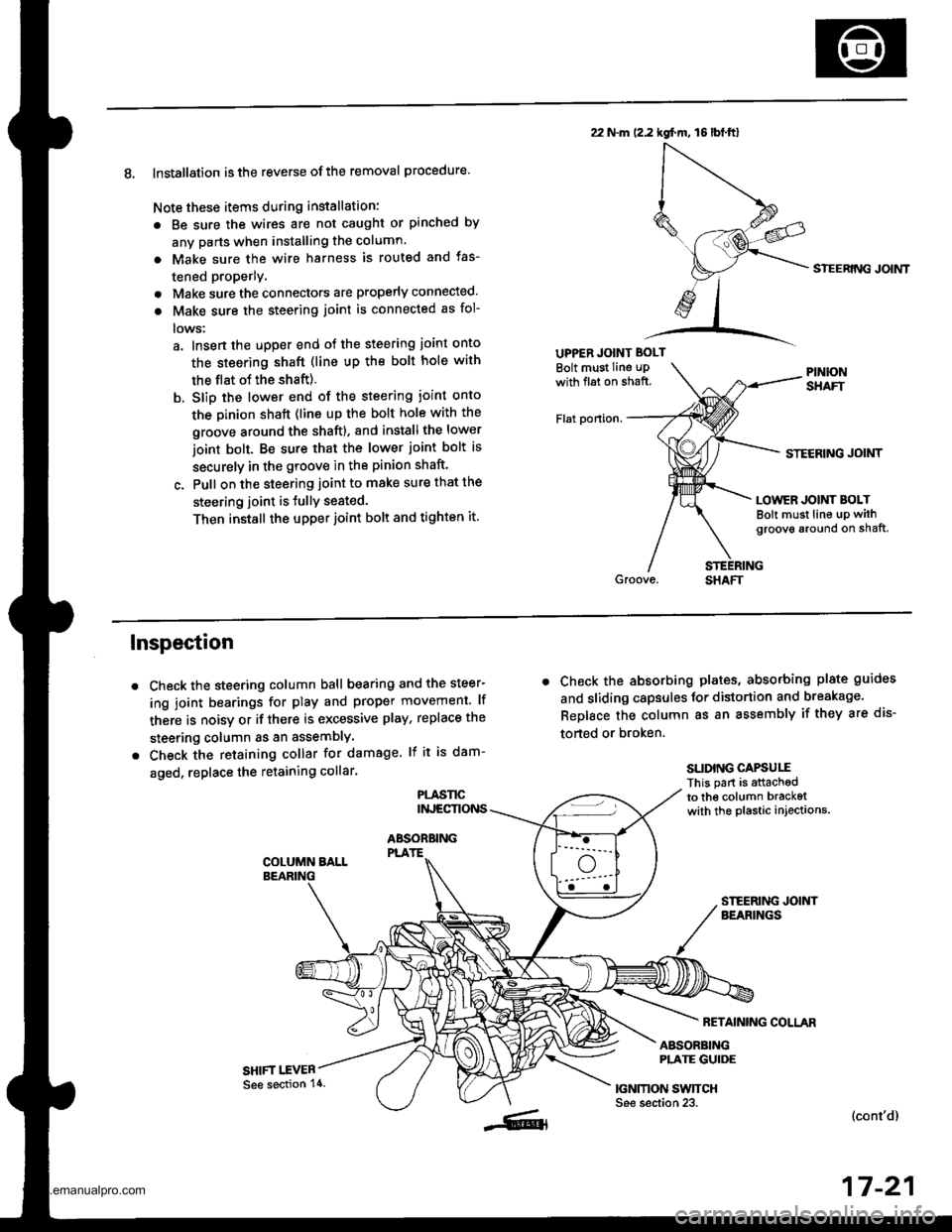
8. Installation is the reverse ofthe removal procedure.
Note these items during installation:
. Be sure the wires are not caught or pinched by
any parts when installing the column.
a Make sure the wire harness is routed and fas-
tened properly.
. Make sure the connectors are properly connected.
. Make sure the steering joint is connected as fol-
lows:
a. lnsert the uDper end of the steering joint onto
the steering shaft (line up the bolt hole with
the flat ot the shaft).
b. Slip the lower end of the steering ioint onto
the Dinion shaft (lins up the bolt hole with the
groove around the shaft). and installthe lower
ioint bolt. Be sure that the lower joint bolt is
securely in the groove in the pinion shaft'
c. Pull on the steering joint to make sure that the
steering joint is JullY seated.
Then install the upper joint bolt and tighten it.
22 N.m (2.2 kgf.m, 16lbt.ftl
UPPER JOINT BOLT
Bolt must Iine uPwith fl6t on shaft.
Flat ponion.
SIEERING JOIMT
STECRING JOINT
LOWER JOINT BOLTBolt must line up withgroove around on shaft,
Inspection
Check the steering column ball bearing and the steer-
ing joint bearings for play and proper movement. lf
there is noisy or if there is excessive play, replace the
steering column as an assemblY
Check the retaining collar for damage. lf it is dam-
aged, replace the retaining collar.
PLASl'tCINJECTIONS
ABSOBBINGPLATE
SHIFT I.EVER
. Check the absorbing plates, absorbing plate guides
and sliding capsules Jor distortion and breakage.
ReDlace the column as an assembly if they are dis-
torted or broken.
SLIDING CAPSUIIThis part is attachedto the column bracketwith the plastic injections.
FETAINING COLLAR
ABSORBINGPLATE GUIDE
|GNMON SWTTCHSee section 23.(cont'd)
17-21
See section 14.
www.emanualpro.com