HONDA INTEGRA 1994 4.G Workshop Manual
Manufacturer: HONDA, Model Year: 1994, Model line: INTEGRA, Model: HONDA INTEGRA 1994 4.GPages: 1413, PDF Size: 37.94 MB
Page 1181 of 1413
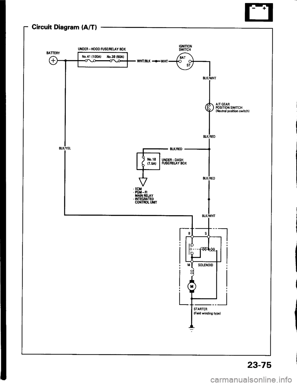
Circuit Diagram (A/T)
G?{raoswncH
6i\-{€ o+
\_v I
IBl-torvHT
II
I,(h A/I GEAR
g, ffi.:11?[:#ir11,",,
I
IBI.K/BED
UI{DER -HOOD FUSE/NEUY BOX
N,0.41 {l00Al Io.39160 t
Page 1182 of 1413
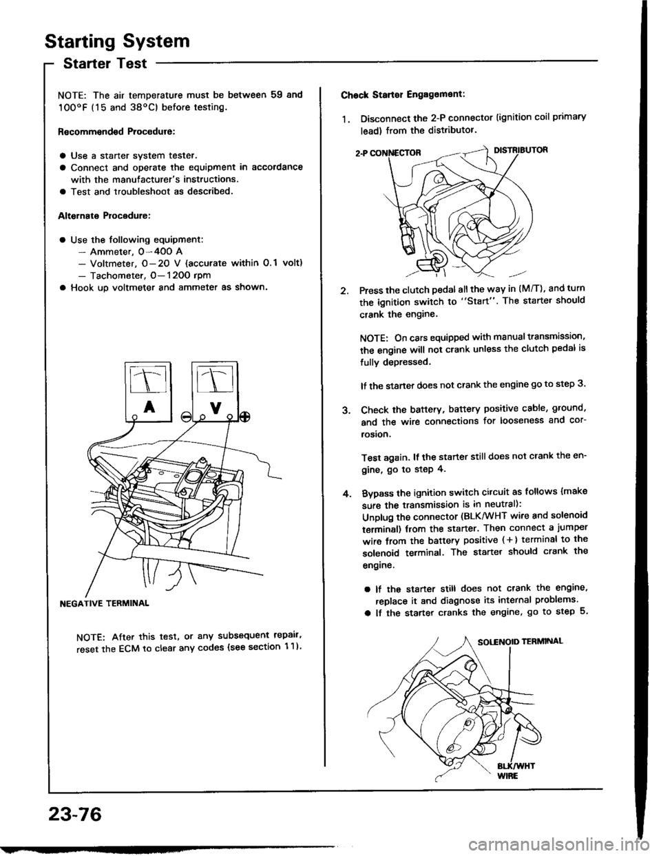
Starting System
Startel Test
NOTE: The air temDerature must be between 59 8nd
10OoF (15 and 38oC) before testing.
Recommendsd Procodure:
a Use a staner svstem tester.
a Connect and operate the equipment in accordance
with the manutacturer's instructions.
a Test and troubleshoot as described.
Altohato Procedure:
a Use the following equipment:- Ammeter. 0-4OO A- Voltmeter, O- 20 V {accurate within 0.1 volt)
- Tachometer, O- 120O rpm
a Hook up voltmeter and ammeter as shown'
NEGATIVE TERMINAL
NOTE: After this test, or any subsequent repair,
reset the ECM to clear any codes (see section 1 1)
23-76
2.
Chock Stan€r Engag6ment:
1. Disconnect the 2-P connector (ignition coil primary
lead) from the distributor.
Press the clutch pedal allthe way in (M/T), and turn
the ignition switch to "Start". The starter should
crank the engine.
NOTE: On cars equipped with manual transmission,
the engine will not crank unless the clutch pedal is
fully depressed.
lf the staner does not crank the engine go to step 3.
Check the baftery, battery positive cable, ground,
and the wire connections for looseness and cor-
rosion,
Test again. lf the starter still does not crank the en-
gine, go to step 4.
Bvpass the ignition switch citcuit as follows {make
sure the transmission is in neutral):
Unplug the connector (BLK/WHT wire and solenoid
terminsl) trom the starter. Then connect a jumper
wire from the battery positive ( + ) terminal to the
solenoid terminal. The starter should crank the
engrne.
a lf the starter still does not crank the engine,
replace it and diagnose its internal problems.
a lf the starter cranks the engine, go to step 5.
J.
4.
Page 1183 of 1413
5. Check lor 8n op€n in the BLKMHT wire circuit be-
tween the staner and ignition switch, and con-
nectors.
6. Check the ignition switch (see page 23-70).
7, On cars with automatic transmission, check the A/Tgear position switch (neutral position switchl and
connector. On cars with manualtransmission, check
the staner cut relay, clutch interlock switch, and
connectors.
NOTE: Check the No. 39 (5O A) fuse in the under-hood
fuse/relay box for the starter cut relay.
Check tor Woar and Damago:
The starter should crank the engine smoothly and stead-
ily. lf th€ startsr engages, but cranks the engine errati-
cally, remove it. Inspect the starter, drive gear, and
flywheel ring gesr for damage.
a Check the drive gear overunning clutch for binding
or slipping when the armature is rotated with the drivegear held. Replace the gesrs if damaged.
Check Cranking Voltago 8nd Current Draw:
Cranking voltage should be no less than 8.O volts.
Current draw should be no more than 360 amperes.
lf cranking voltag€ is too low, or current draw too high,
check for:
a Fully charged battery
a Open circuit in starter armature commutatot segments
a Starter armature dragging
a Shoned armature winding
a Excessive drag in engine
Chack Cranking rpm:
Engine spsod during cranking should be above 1O0 rpm.
lf spe6d is too low, ch€ck for:
a Loose battsry or starter teminals
a Excessively worn starter brushes
a Open circuit in commutator segments
a Dirty or damaged helical spline or drive gear
a Defective drive gear overrunning clutch
Chock StErtor Disongagomoni:
Press the clutch pedal allth€ way in (M/T), turn the ioni-
tion switch to "lll" and rolease to "11".
The starter drive gear should disengage from the tlywheel
ring gear. When you rolease the key.
lf the drive gear hangs up on th€ flywheel ring gear, check
for:
a Solenoid plunger and switch malfunction
a Dirty drive gear assembly or damaged overrunning
clutch
23-77
Page 1184 of 1413
Starting System
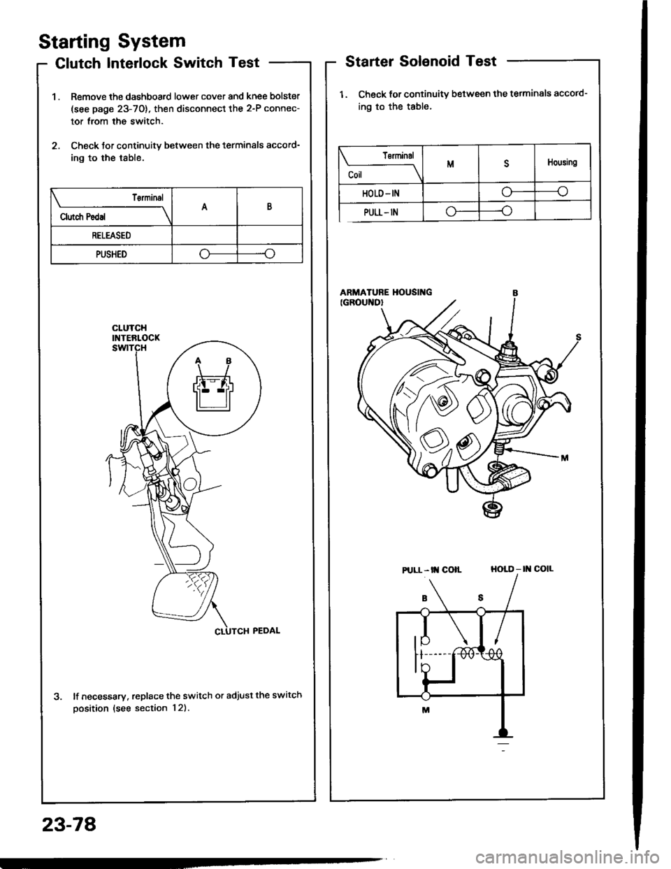
Clutch Interlock Switch Test
1 . Remove the dashboard lower cover and knee bolster
(see page 23-70), then disconnect the 2-P connec-
tor from the switch.
2. Check tor continuity between the terminals accord-
ing to the table.
lf necessary. replace the switch or adjust the switch
oosition (see section 12).
Starter Solenoid Test
1. Check for continuitv between the tetminals accotd-
ing to the table.
HOLD - |l{ COIL
23-78
Tsrminal
CoilMDHousing
HOLD- INo----c
PULL- INo----.oClutch Pedal
T€rminalAB
RELEASED
PUSHEDoo
Pt LL- tt{ coll
Page 1185 of 1413
1.
2.
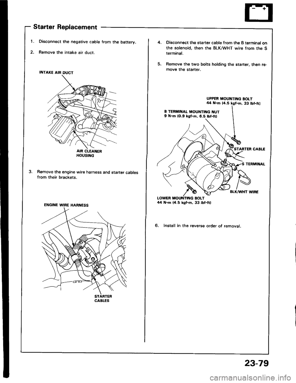
Starter Replacement
Disconnect the negative cable from the batterv.
Remove the intake air duct.
AIR CIEANERHOUS|L
Remove the engine wire harness and startef cablesfrom their brackets.
ENGINE WIRE HARI{ESS
CAALES
4.Disconnect the staner csble from the B terminal onthe solenoid, then the BLK/WHT wire from the Sterminal.
Remove the two bolts holding the staner, then re-move the startef.
UPPER MOUI{TII{G BOLT44 N..h (4.5 kgl.m, 33 lbt,ftl
8 TERMII{AL MOUIITTI{G NUT9 .ln (0.9 kgf.m, 6.5 tbf.ttl
TERMINAL
BLI(AA/HT WIRE
6. Install in the reverse order of removal,
23-79
Page 1186 of 1413
![HONDA INTEGRA 1994 4.G Workshop Manual Starting
Startel
System
Overhaul
from clutch side.
-s@]
MOLYBDENUMDISULFIDE
CAUTION: Disconnecl th€ battery n€gative cable befole
lomoving the startet.
NOTE: The original radio has a coded theft p HONDA INTEGRA 1994 4.G Workshop Manual Starting
Startel
System
Overhaul
from clutch side.
-s@]
MOLYBDENUMDISULFIDE
CAUTION: Disconnecl th€ battery n€gative cable befole
lomoving the startet.
NOTE: The original radio has a coded theft p](/img/13/6067/w960_6067-1185.png)
Starting
Startel
System
Overhaul
from clutch side.
-s@]
MOLYBDENUMDISULFIDE
CAUTION: Disconnecl th€ battery n€gative cable befole
lomoving the startet.
NOTE: The original radio has a coded theft protection
citcuit. Be sure to get the customer's code number before
- disconnecting the batterY.- removing the No.3 2 (7.5 A) fuse from the under-hood
fuse/relay box.- removing the tadio.
Atter service, reconnect power to the radio and turn at
on. When the word "CODE" is displayed, enter the cus-
tomer's 5-digit code to restore radio operation.
tr./.' BRUSH HOLDERTest, page 23-8'l
ERUSH
COVER
I
6
OVERRUNNING CLUTCH ASSEMBLYInspection, page 23_84
SOLENOIDPLUNGERInspection, page 23-85
BRUSH HOLOER
ARMATURE
STARTERSOLENOIDTest, page 23-78
PINION GEAR IDLER GEAR
Inspection, page 23-11
IDLER GEAR
I
@*
SOLENOID HOUSING
HARNESS BRACKET
STEEL BALL
install steel ball
lnspection and Test,page 23-82
ROLLER BEARINGSand CAGEPrevenl rollers trom being scattered and lost.
MOLYBDENUM DISULFIDE
_R1
MOLYADENUMDISULFIDE
23-80
ENO COVER
ARMATURE
GEAR HOUSING
Page 1187 of 1413
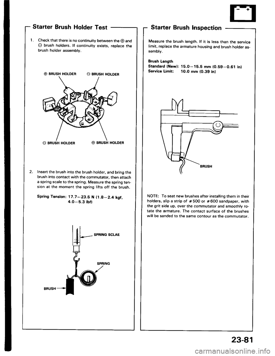
Starter Brush Holder Test
1 . Check that there is no continuity between the O and
O brush holders. lf continuity exists. replace theb,ush holder assembly,
G) BRUSH HOLDER E BRUSH HOLOER
O BRUSH I{OLDERO BRUSH HOLDER
Insert the brush into the brush holder, and bring thebrush into contact with the commutator, then attacha spring scale to the spring, Measure the spring ten-sion at the moment the spring lifts off the brush.
Spring Tension: 17.7 -23.5 N {1.8-2.4 kgf,4.O_5.3 tbfl
SPRING SCLAE
Starter Brush Inspection
Measure the brush length. lf it is less than the servicelimit, replace the armature housing and brush holder as-sembly.
Brush L€ngth
Standard {Now): 15.O- 15.5 mm (0.59-0.61 inlSe.vice Limit: 10.0 mm (0.39 inl
NOTE: To seat new brushes after installing them in their
holders, slip a strip of # 5OO or # 600 sandpaper, with
the grit side up. over the commutator and smoothly ro-
tate the armature. The contact surface of the brushes
will be sanded to the same contour as the commutato..
23-81
Page 1188 of 1413
Starting System
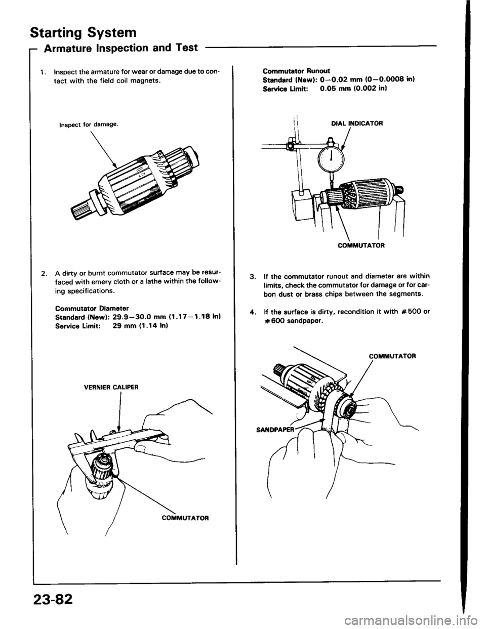
Armature Inspection and Test
1 . Inspect the armature for wear or damage due to con-
tact with the field coil magnets.
Inspect tor damage
A dirtv or burnt commutator surface may be l€sul-
faced with emery cloth or a lathe within the follow-
ing specilications.
Commutator Diamet€r
Stsndald (N6w): 29.9-3O.O mm (1.17-1.18Inl
Selvico Limit: 29 mm (1.14 lnl
VERNIEB CALIPER
23-82
3.
4.
Commutrtor Runout
Standard (Naw): 0-O.O2 mm (0-O.OO08 inl
Sowico Limit: 0.O5 mm (O.O02 inl
lf the commutator runout and diamete. are within
limits, check the commutator tor damage or for car-
bon dust or brass chips between the segments.
lf the surf6c6 is dirty, recondition it with # 50O or
# 600 sandpsper.
COMMUTATOR
Page 1189 of 1413
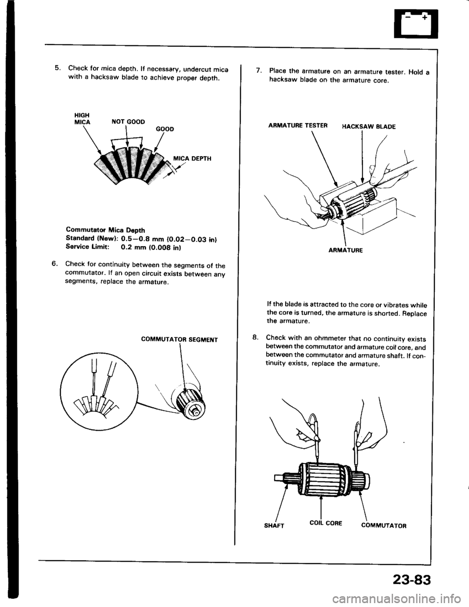
Check for mica depth. It necessary, undercut micawith a hacksaw blade to achieve proper depth.
ITOT GOOO
MICA DEPTH
Commutator Mica D6pth
Stsndard {Nsw):0.5-0.8 mm (O.O2-0.03 in}Sslvice Limit: 0.2 mm (O.OO8 inl
Check tor continuity between the segments of thecommutator. lf an open circuit exists between anvsegments, replace the armatute.
M
ARMATURE TESTER
ARMATUFE
Place the armatute on an armature tester. Hold ahacksaw blade on the armature core,
HACKSAW BLADE
It the blade is attracted to the core or vibrstes whilethe core is turned, the armature is shorted. Reolacethe armature.
Check with an ohmmeter that no continuity existsbetween the commutator and armatute coilcore. andbetween the commutator and armature shaft. lf con_tinuity exists, replace the armature
COMMUTATOR
8.
SHAFT
23-83
Page 1190 of 1413
BRUSHES
Starting System
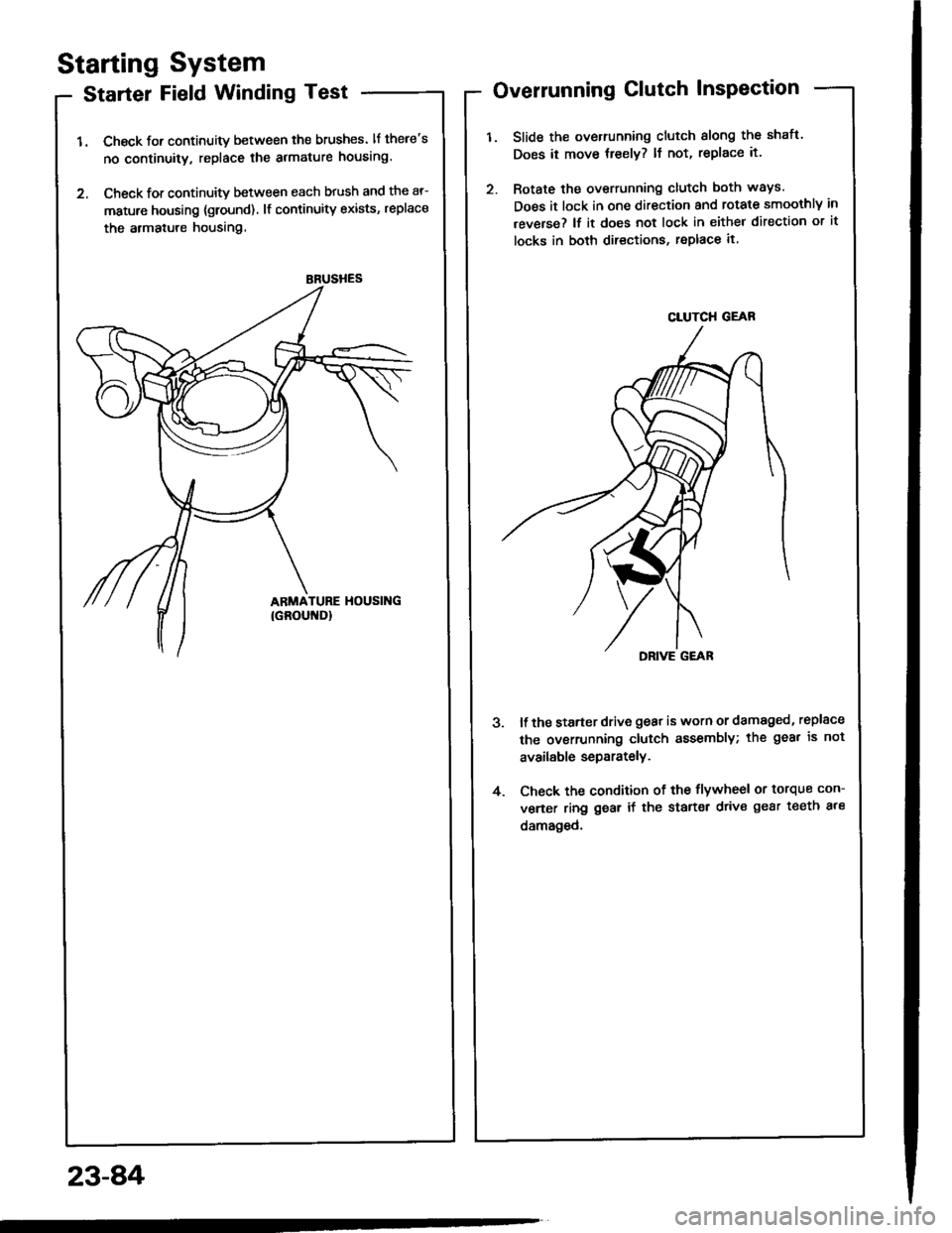
Starter Field Winding Test
1. Check for continuity between the brushes. lf there's
no continuity, replace the armature housing.
2. Check for continuity between each brush and the ar-
mature housing {ground) lf continuity exists, replace
the armatule housing.
Overrunning Clutch InsPection
Slide the overrunning clutch slong the shatt.
Does it move treely? ll not, replace it.
Rotate the overrunning clutch both ways.
Does it lock in one direction and rotate smoothly in
reverse? lf it does not lock in either direction or it
locks in both directions, replace it.
DRIVE G€AR
ll the starter drive gear is worn or damaged, replsce
the ovsrrunning clutch assembly; the gea. is not
available separately.
Check the condition of the flywheel or torque con-
verter ring gear if the starter drive gear teeth ale
damaged.
4.
23-8,4
CLUTCH GEAR