HONDA INTEGRA 1994 4.G Workshop Manual
INTEGRA 1994 4.G
HONDA
HONDA
https://www.carmanualsonline.info/img/13/6067/w960_6067-0.png
HONDA INTEGRA 1994 4.G Workshop Manual
Trending: alternator circuit, distributor circuit, Detent spring, warranty, Flywheel cover, Timing marks, O2 sensor
Page 1211 of 1413
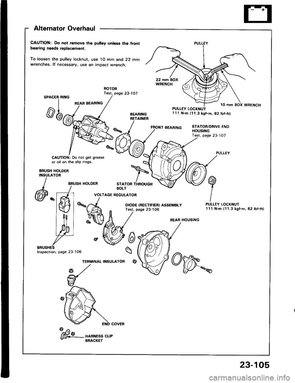
Alternator Overhaul
CAUTION: Do not r€move th€ pulley unl€Es the t.ontbearing needs r6placsm6nt.
To loosen the pulley locknut, use 10 mm and 22 mmwrenches. It necessary, use an impact wrench.
Test, page 23-107SPAC
REAR BEARING
ER RING
rl
@n
CAUTION: Do not get grease
or oil on the slip rings.
HOLDERTOR
ARUSH HOLOER
FRONT BEARING
PULLEY LOCKI{UT1'll N.m 111.3 kgt.m,82 tbf.trl
STATOR/DRIVE ENDHOUStt{G
BBUSHINSULA
)
(@P "
STATOR THROUGHBOLT
VOLTAGE REGULATOR
DIODE IRECTIFIER) ASSEMBLYTest, page 23-106
6
q
%A
re
TERMINAL INSULATORqt
PULLEY LOCKNUT111 N.m (1 1.3 kgt.m, 82 lbf.ft)
PULLEY
10 mm BOX WRENCH
REAR HOUSING
Inspection, page 23-
fu"- "o*n.r" ".,"- BRACKET
23-105
Page 1212 of 1413
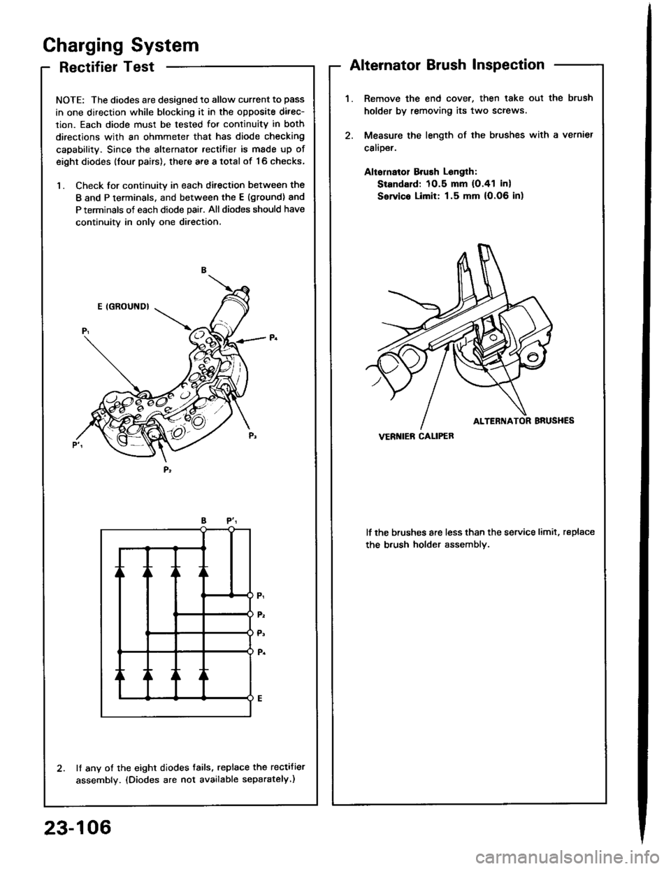
RectifierTest
NOTE: The diodes are designed to allow current to pass
in one direction while blocking it in the opposite direc-
lion. Each diode must be tested for continuitv in both
directions with an ohmmeter that has diode checking
capability. Since the alternator rectifier is made up of
eight diodes (four pairs), there are a total of '16 checks,
1. Check for continuity in each ditection between the
B and P terminals, and between the E (ground) and
P terminals of each diode pair. All diodes should have
continuity in only one direction,
lf any of the eight diodes tails, replace the rectifier
assembly. (Diodes are not available separately.)
Gharging System
Alternator Brush Inspection
Remove the end cover, then lake oul the brush
holder by removing its two screws
Measure the length of the brushes with a vernier
calioer.
Aliornatol Brush Longlh:
Standard: 10.5 mm (O.41 in)
Servic. Limit: 1.5 mm (O.06 in)
lf the brushes are less than the service limit, replace
the b.ush holder assemblv.
VERI{IEB CALIPEB
23-106
Page 1213 of 1413
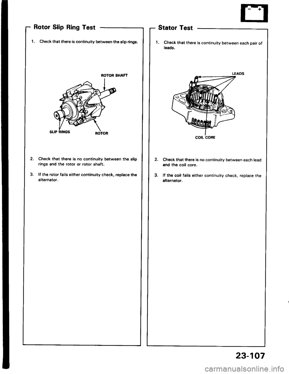
Rotor Slip Ring Test
1 . Check thst there is continuity between thg slip rings.
ROTOR SHAFT
Check th8t there is no continuity betw€en the slip
rings and the rotor or rotor shaft.
lf the rotor fails either continuity check, rsplace th€
alternator.
2
3
Stator Test
1. Chock that there is continuity between each pair ofl6ads.
Ch6ck that there is no continuity between each lead
and the coil core.
lf th€ coil fsils either continuity check. replace the
alt6rnator.
cotl coRE
23-107
Page 1214 of 1413
Charging System
Alternator Belt Inspection and Adjustment
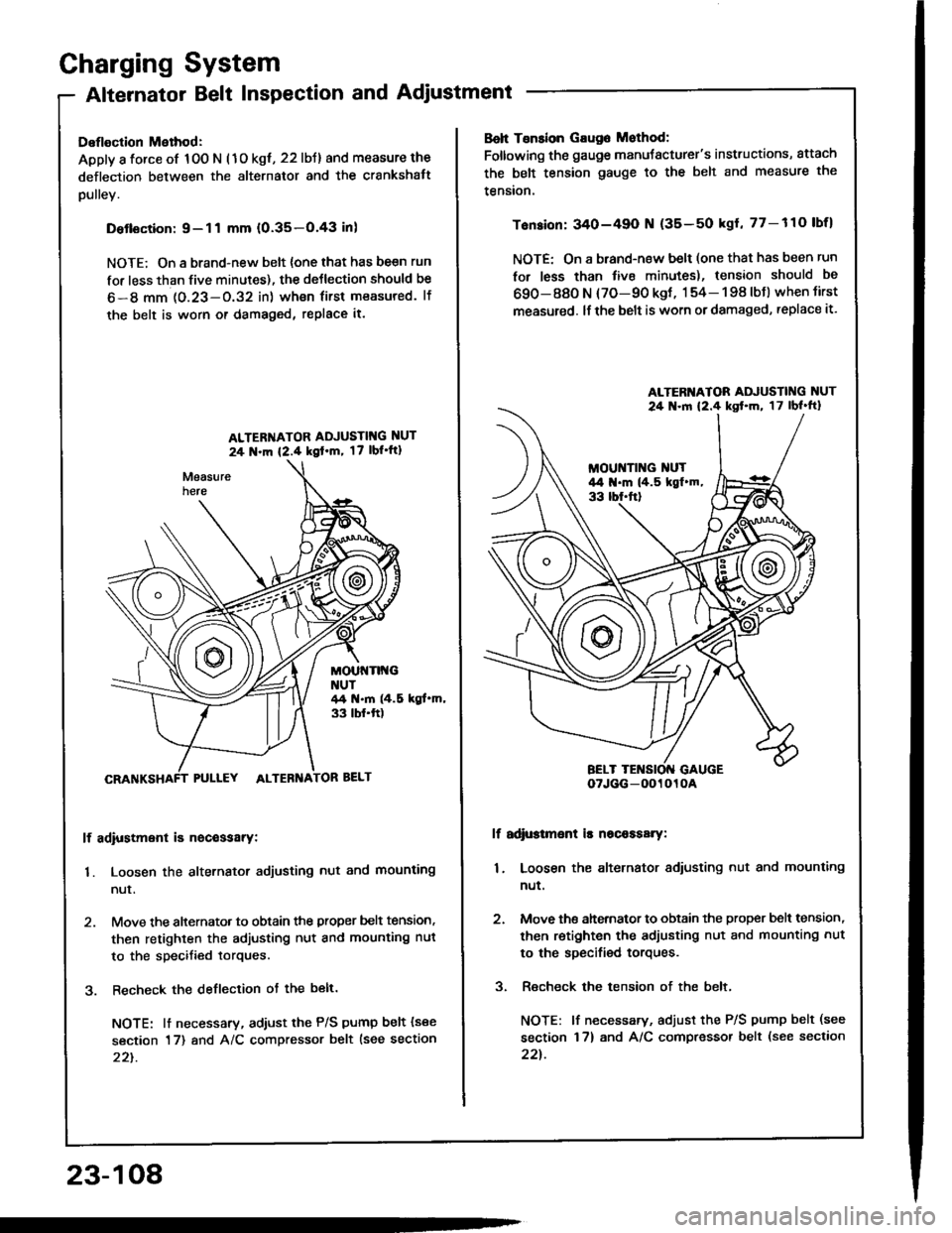
Deflection Method:
Apply a force of 100 N (1o kgt, 22 lbJ) and measure the
deflection between the alternator and the crankshatt
pulley.
Detlsction:9-11 mm (0.35-O.43 inl
NOTE; On a brand-new belt {one that has be€n run
for less than five minutes), the deJlection should be
6-8 mm 1O.23-O.32 in) wh€n first measured. lf
the belt is worn or damaged, replace it.
ALTER'{ATOR ADJUSTIT{G NUT
24 N.m {2.4 kgl'm, 17 lbl'ft1
MOUt{Tlt{GNUT44 t{.m (4.5 kgt.m,33 tbf.ft)
PULLEY ALTEBNA
lf adiustment is nocessarY:
1. Loosen the alternator adjusting nut and mounting
nur.
2. Move the alternator to obtain the proper belt tension,
then retighten the adjusting nut and mounting nut
to the specified torques.
3. Recheck the deflection ot the belt.
NOTE: lt necessary, adiust the P/S pump belt (see
section 17) and A/C compressor belt lsee section
22t.
23-108
Boh Tsnsion Gaug6 Mothod:
Foltowing the gauge manuJacturer's instructions, attach
the belt tension gauge to the belt and measure the
tension.
Tension: 340-49O N (35-50 kgl, 77-110 lbfl
NOTE: On a brand-new belt (one that has been run
for less than tive minutes), tension should be
690-880 N (70-90 kgt, 154- 198 lbJ) when tirst
measured. lf the belt is worn or damaged, replace it.
lf adi$tmsnt is nscaasary:
1. Loosen the alternator adiusting nut and mounting
nut.
2. Move ths ahernator to obtain the proper bslt tension,
then retighten the adjusting nut and mounting nut
to the specified torques.
3. Recheck the tension of the belt,
NOTE: lf necessary, adjust the P/S pump belt (see
section 17) and A/C compressor belt (see section
22t.
ALTERI{ATOR ADJUSTING NUT
24 .ln 12.4 kst'm, 17lbl'ft}
oTJGG-0O1010A
Page 1215 of 1413
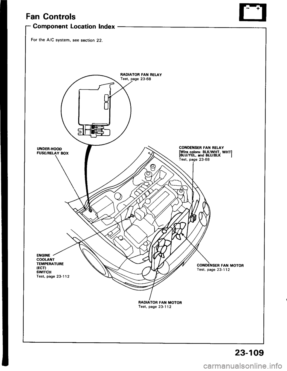
Fan Gontrols
Component Location Index
For the A/C system, see section 22.
UNDER-HOODFUSE/RELAY BOX
RADIAIOR FAN REI.AYTest, page 23-68
CONDCNSER FAI{ BELAYlwir6 color3: ELKnirHT, WHTIIBLUryEL, and BLU/BL( ITest, page 23-68
ENGII{EcooLA TTEMPERATURE{ECT)SwlTCHTesr, page 23-'l 12
FAN MOTORTest, page 23-112
BADIATOR FAN MOTORTest, page 23-1 12
23-109
Page 1216 of 1413
ul{o€R - DAstlGIINONSWITCH FUSC/RELAYBOX
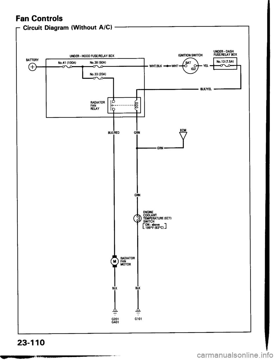
Circuit Diagram (Without A/Cl
UI{OER - HOOD FUS€/REI.AY BOX
6r F'rrr^'l.{ ots YEt {<\o*r
\-Y -l
ECM
V
Gtr{
l,*^,
($fffiHil'r"n.''
I
t?i'r?Tdf.ol
I
ffi,"'l
IBtl(
I
I:
G10l
Fan Controls
23-110
No.4l {lmA, No.39l50Al
FIIF.-
Page 1217 of 1413
G FION SWIICH
No.41 l100Al No.39l50At
RAOIATORFANREI.AY
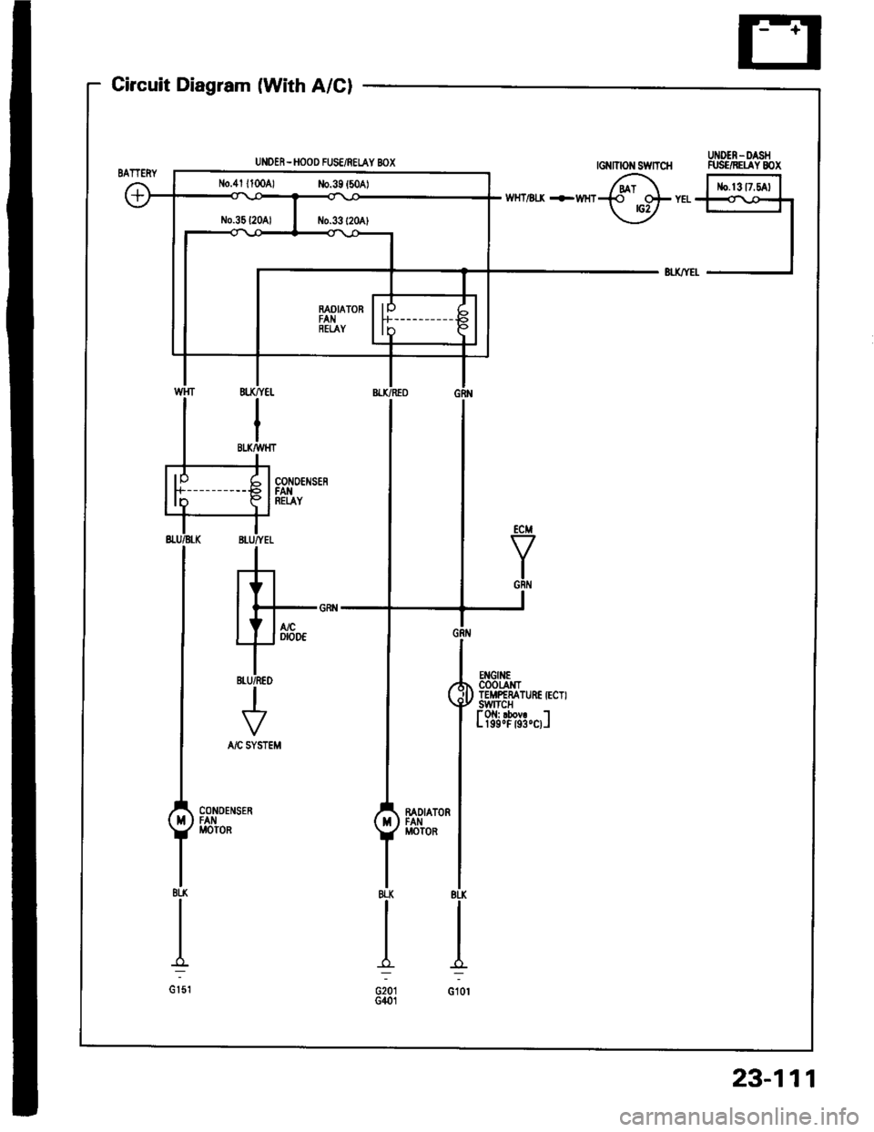
Gircuit Diagram (With A/Cl
UNOER - HOOO FUSE/REIAY BOX
,5
GRt{
| ,*n,n,,z*r CoOtAt{TqU llffffarunErEcrr
I
t?i'i."1",i:"ol
Imonron IFAN IMOTOR
I
IBI-K
I
I:
G10l
23-111
Page 1218 of 1413
Fan Controls
Fan Motor Test
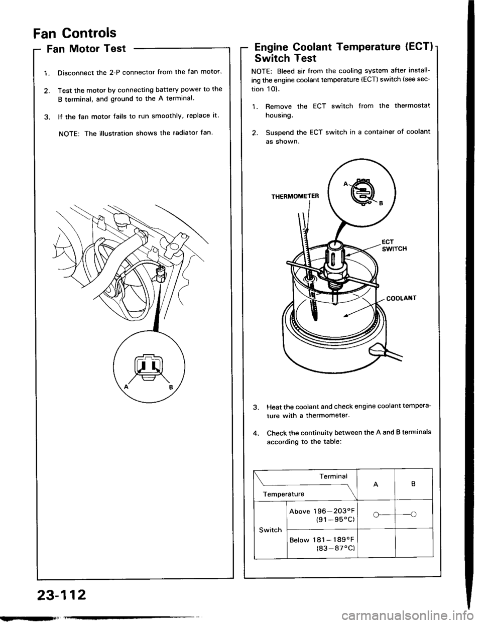
1. Disconnect the 2-P connector from the fan motor.
2. Test the motot by connecting battery power to the
B terminal, and ground to the A terminal
3. lf the Jan motor fails to run smoothly, replace it.
NOTE: The illustration shows the radiator fan.
Engine Coolant Temperature (ECT)
Switch Test
NOTE: Bleed air from the cooling system atter install-
ing the engine coolant temperature (ECT) switch (see sec-
tion 1O).
1. Remove the ECT switch from the thermostat
housing.
2. Suspend the ECT switch in a container of coolant
as shown.
Heat the coolant and check engine coolanl tempera-
ture with a thermometer.
Check the continuity between the A and B terminals
according to the table:
Terminal
;;,".,"---\
B
Switch
Above 196 2O3"F
{91-95'C)o_-o
Below 181- 189oF
(83-87'C)
23-112
Page 1219 of 1413
Gauge Assembly
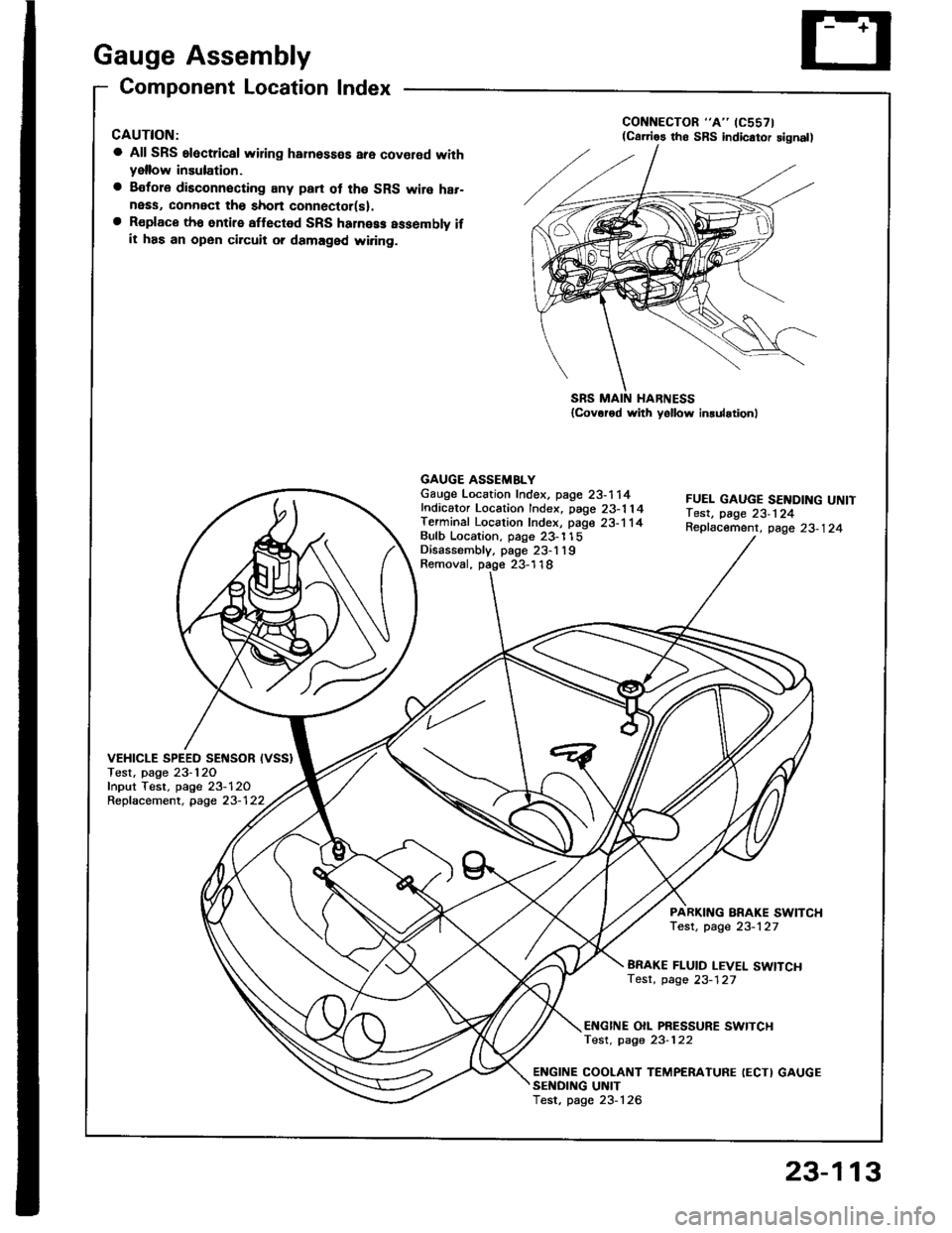
Component Location Index
CAUTION:
a All SRS electrical wiring harnosses are cov€rod withyellow insulation.
a Bofore disconnecting any prn ot th€ SRS wire har-ness, connect tho short connector(sl.a R€place th6 entirs affGcted SRS halne$ assembly ifit has an open circuit o? damaged wiring.
SRS MAIN HARNESS{Cov.r6d with yollow inrularionl
GAUGE ASSEMBLYGauge Location Index, page 23-114Indicator Location Index, page 23-1 14Terminal Location Index, page 23-114Bulb Location. page 23-'l 15Disassembly. page 23-1 19Removal, page 23-118
FUEL GAUGE SENDING UNtTTest, page 23'124Repfacemenr, page 23-124
VEHICLE SPEEO SENSOB IVSS}Test, page 23-120fnput Test. page 23-120Repfacement, page 23-122
PARKITTG BRAKE SWITCHTest, page 23-127
BRAKE FLUID LEVEL SWITCHTesr, page 23-127
EI{GINE OIL PBESSURE SWITCHTest, page 23-122
ENGINE COOLANT TEMPERATURE IECTI GAUGESENOING UNITTest, page 23-126
(C61'ios tho SBS indicator signal)
23-113
Page 1220 of 1413
Gauge Assembly
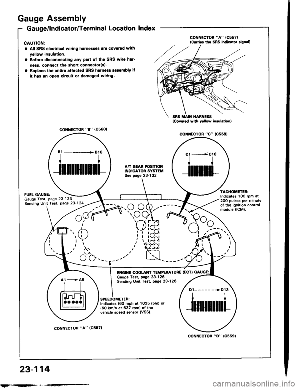
Gauge/lndicator/Terminal Location Index
CAUTIOI{:
a All SRS olectrical wiring harnessos aro covorod with
yellow insulation,
Belol€ disconnecting any part ot tho SRS wiro hat-
nesa. connoct the short connoctol(El.
Replaco th6 entire aff6cted SRS hamess sssombly lf
it has an open circuil or damagod widng.
co r{EcroR "c" (c558}
FUEL GAUGE:Gauge Test, page 23-123
Sending Unit Tost, page 23-124
23,-114
A/T GEAR POSIT|OIIDICATOR SYSTEISee pags 23-132
E GI[{E COOLAI{T TEIIPEFATURE IECTIc6uge TEst, p6g6 23-126Sending Unit Tsst, pago 23-126
TACHOMETER:Indicatos lOO rpm at20O puls€s per minul€of the ignition controlmodul€ llCM).
SPEEDOMETER:Indicates (60 mph 6i 1025 rpml or{60 km/h at 637 rem) of th€v€hicle spe6d sonsor lVSSl.
CoNNECTOR "8" (c5601
Bi ----------+ B16Cl ----+ClO
f',. /i)
)Y
-"b
\_./ \J \-___--
a1 -----> A5
Dl-------.>D13
col{]{ECTOR "D" (C5591
rtrF --
coNNECfOR "A" (C557)
Trending: Idle, Stereo circuit, engine coolant, ESP, G1 T1, differential, oil change
