HONDA INTEGRA 1994 4.G Workshop Manual
INTEGRA 1994 4.G
HONDA
HONDA
https://www.carmanualsonline.info/img/13/6067/w960_6067-0.png
HONDA INTEGRA 1994 4.G Workshop Manual
Trending: seat adjustment, camshaft, Bearings, camshaft seal, heater, door panel, headrest
Page 1281 of 1413
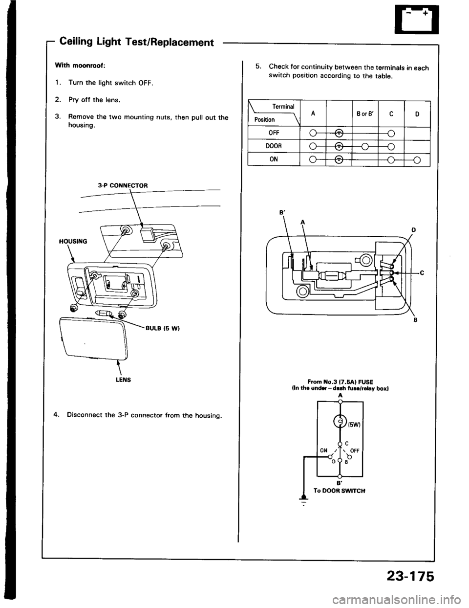
Ceiling Light Test/Replacement
With moonrool:
1. Turn the light switch OFF.
2. Pry otJ the lens.
3. Remove the two mounting nuts, then pull out thehousing.
4. Disconnect the 3-P connector f.om the housing.
3-P CONNECTOR
re.mrnal
Position \A8or8'cD
OFFo-za--o\7
DOORo---o\7
ONG-/1--o\:.,/
5. Check for continuity between the terminals in €schswatch position according to the table.
F om o.3l7.5Al FUSE(ln th. snd.. - dr.h fu!./r€by boxl
23-175
Page 1282 of 1413
Geiling/Trunk/Cargo Area Lights' Spotlights
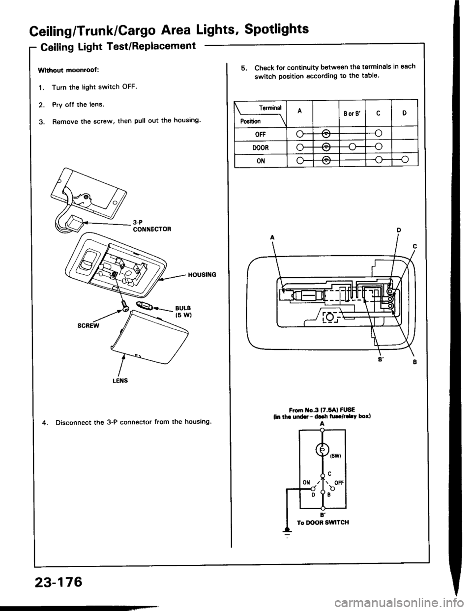
Geiling Light Test/Replacement
Without moonroot:
1. Turn the light switch OFF.
2. Pry ofJ the lens.
3. Remove the sctew, then pull out the housing'
4. Disconnect the 3-P connector from the housing.
3-PCONNECTOR
23-176
T6ninsl
P"riti"" \
ABor B'D
OFFo-/:\--o\:.,/
DOORo-A--o
ONLF/A--o
5. Check for continuity between the terminals in each
switch position according to the table.
F om o.3l7.5Al FUSEtln thr uid.r - ddr h|. /,.LY borlA
Page 1283 of 1413
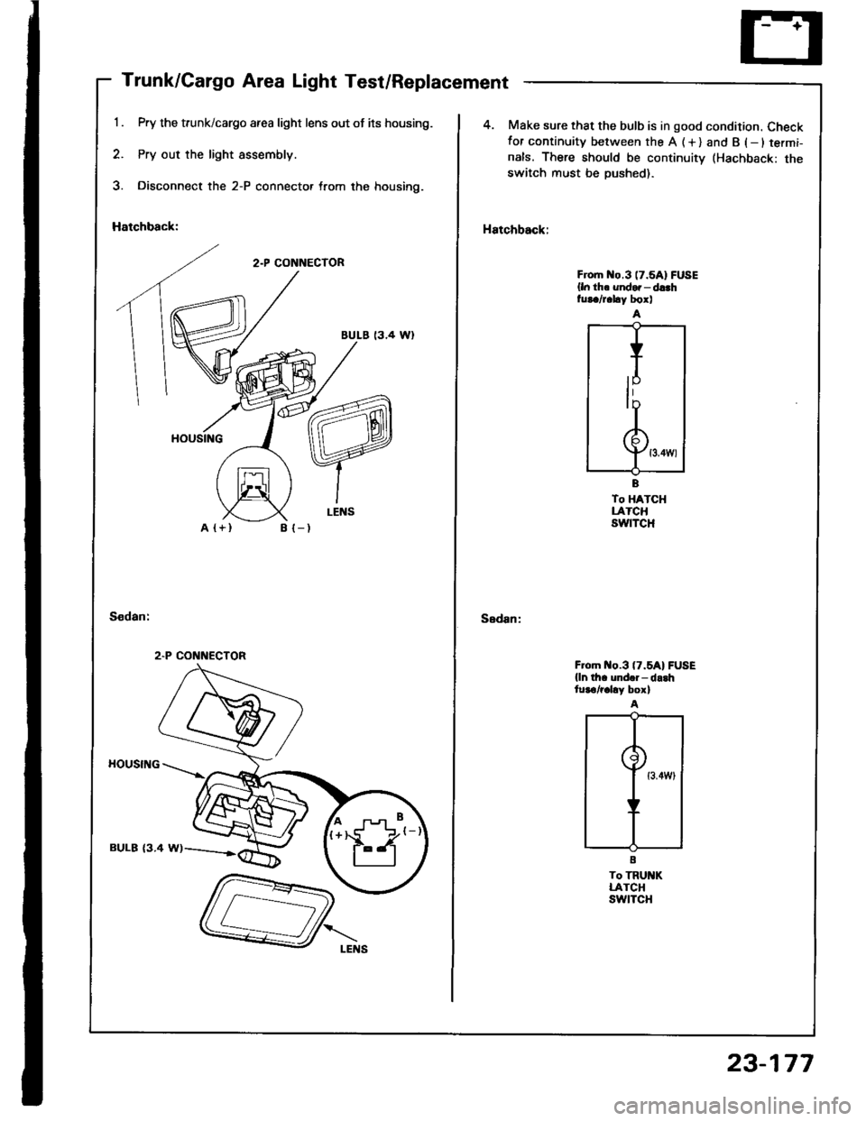
Trunk/Cargo Area Light Test/Replacement
Pry the trunk/cargo afea light lens out of its housing.
Pry out the light assembly.
Disconnect the 2-P connector trom the housing.
Hatchback:
2.P CONNECTOR
BULE 13.4 Wl
A {+}B {-)
HOUSING
BULB {3.4 W)
2.P CONNECTOR
4. Make sure that the bulb is in good condition. Checkfor continuity between the A (+) and B (-ltermi-
nals. There should be continuitv (Hachback: theswitch must be Dushed).
Hatchback:
Sedan:
Froh o.3 (7.5A1FUSE
{ln th. undor - d!.hfur./r.hy box)
To HATCHLATCHswtTcH
F om o.3 (7.5A1FUSE
{ln th. und.i- da.htur€/r.hy box)
To TRU KLATCHswtTcH
23-177
Page 1284 of 1413
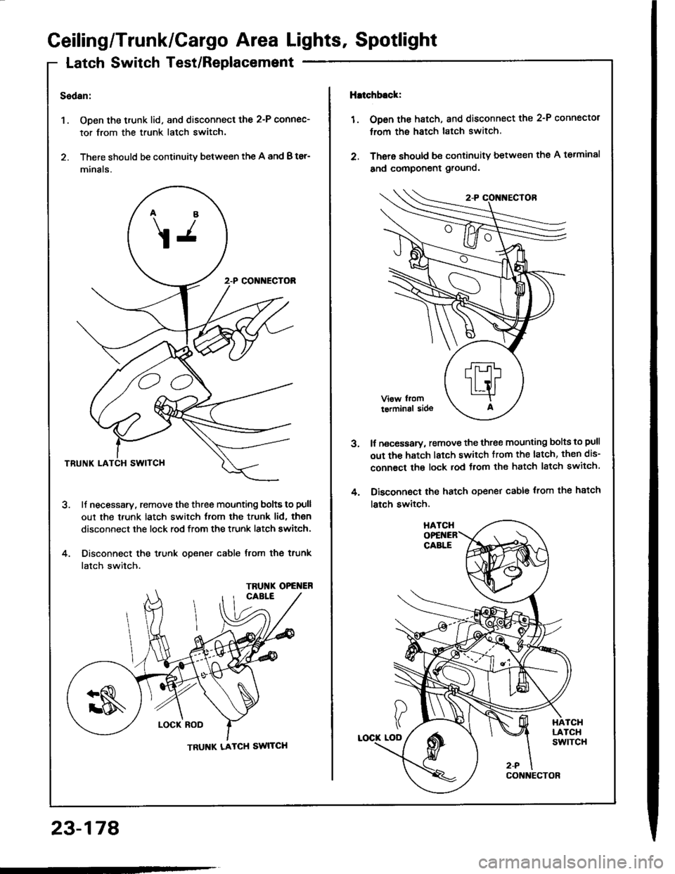
Ceiling/Trunk/Cargo Area Lights, Spotlight
Latch Switch Test/Replacemsnt
Sedan:
1. Open the trunk lid. and disconnect the 2-P connec-
tor from the trunk latch switch.
2. There should be continuity between the A and B ter-
minals.
ll necessary, remove the three mounting bolts to pull
out the trunk latch switch from the trunk lid, then
disconnect the lock rod from the trunk latch switch.
Disconnect the trunk opener cable from the trunk
latch switch.
4.
\j
CC
TRU'{K OPG ER
TRUNK LATCH SWITCH
lhtchb.ck:
1 . Op6n the hatch, and disconnect the 2-P connector
trom the hatch latch switch.
2. There should be continuity between thg A terminal
and component ground.
lf necessary, remove the three mounting bolts to pull
out the hatch latch switch trom the latch, then dis-
connact the lock rod Jrom the hatch latch switch
Disconnect the hatch opener cable trom the hatch
latch switch,
3.
4.
23-178
Page 1285 of 1413
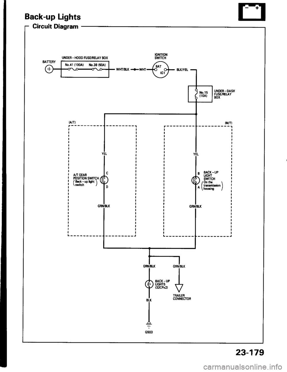
Back-up Lights
Circuit Diagram
wHT/Bt( +WHT
A/T GEARPosrnotr swrTcHf 8ek - up lioht 'l
--------_JL---------
UI{DER_ IIOOO FUSEiBEIAY BOX
23-179
Page 1286 of 1413
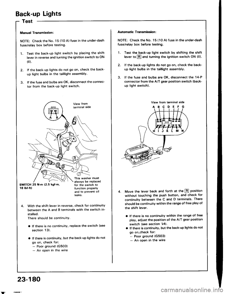
Back-up Lights
Manual Transmigsion:
NOTE: Check the No. 1 5 { 1 O A) fuse in the under-dash
fuse/relay box befote testing.
'1. Test the back-up light switch by placing the shift
lever in reverse and turning the ignition switch to ON
(
).
2. It the back-up lights do not go on, check the back-
up light bulbs in the taillight assembly.
3. lf the tuse and bulbs are OK. disconnect the connec-
tor from the back-up light switch.
terminal sade
This washer must
always be replacedtor the switch tolunction properlY
and to ptevent ollteaKs.
4. With the shift lever in reverse. check Jor continuity
between the A and B terminals with the switch in-
stalled.
There should be continuity.
a lf there is no continuity, replace the switch {see
section 13).
a lf there is continuity, but the back-up lights do not
go on, check for:- Poor ground (G5O3)
- An open in the wire
23-180
Automatic Transmission:
NOTE: Check the No. l 5 ( 1 O A) fuse in the under-dash
fuse/relay box belore testing.
1. Test the back-up light switch by shitting the shift
lever to l3l and turning the ignition switch ON (ll).
2. lf the back-up lights do not go on, check the back-
up light bulbs in the taillight assembly.
3. lf the tuse and bulbs are OK, disconnect the 14-P
connector from the A/T gear position switch (back-
up light switch).
Move the lever back and torth at the LBI position
without touching the push button, and check tor
continuitv between th€ C and D terminals. There
should be continuitY within the range of free plsy of
the shift lever.
a lf there is no continuity within the range oJ J.ee
play, adjust the position ot the A/T gear position
switch lsee section 141.
a lt there is continuity, but the back-up lights do not
go on,check {or:- Poor ground {G503)- An oDen in the wire
4.
Page 1287 of 1413
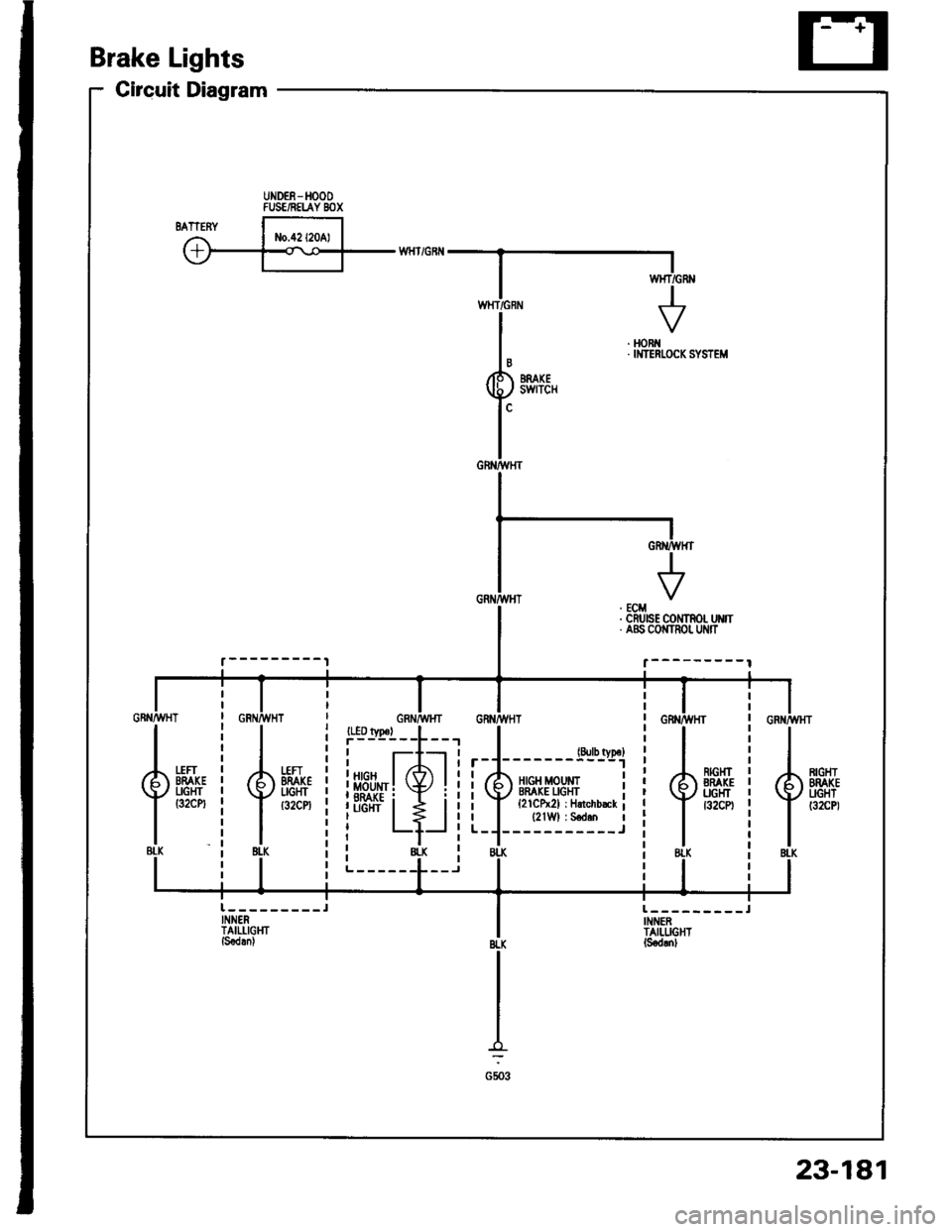
Circuit Diagram
Brake Lights
UNDEE-HOOOFUSE/NELAY BOX
. HORi{. IMTERI.OCK SYSTEM
{.BLK
*H-i
{.{u8tK
23-181
Page 1288 of 1413
AB'|Frt
jr'li
CD
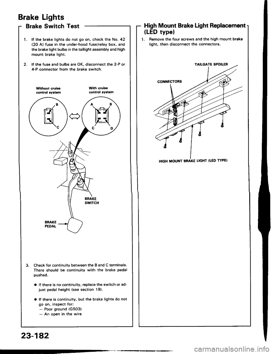
Brake Lights
Brake Switch Test
lf the brake lights do not go on, check the No. 42
{2O A) fuse in the under-hood fuse/relay box, and
the brake light bulbs in the taillighr assembly and high
mount brake light.
lf the fuse and bulbs are OK. disconnect the 2-P or
4-P connector {rom the brake switch.
3. Check fo. continuitv between the B and C terminals.
There should be continuity with the brake pedal
pushed.
a lJ there is no continuitv, replsce the switch or ad-
just pedal height {see section 19).
a lf there is continuity, but the brake lights do not
go on, inspect for:- Poor ground (G5O3)
- An ooen in the wire
High Mount Brake Light Replacement
(LED typel
1. Remove the four screws and the high mount btake
light, then disconnect the connectors.
HIGH ltlOUt{T BRAKE LIGHT {LED TYPEI
23-1A2
Page 1289 of 1413
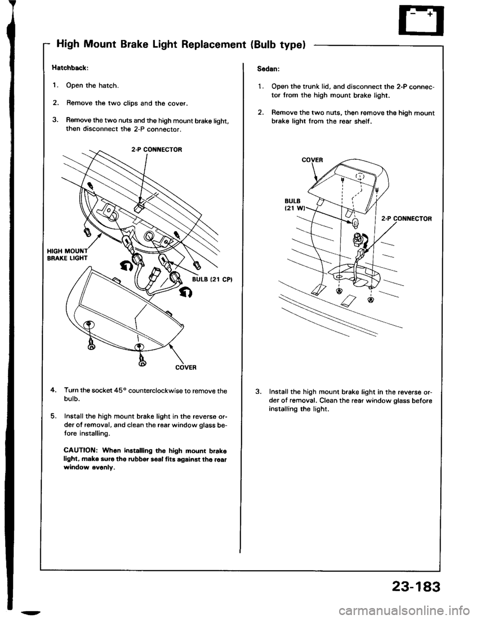
High Mount Brake Light Replacement {Bulb type)
Hatchback:
1. Open the hatch.
2. Remove the two clips and the cover.
3. Remove the two nuts and the high mount brake light,then disconnect the 2-P connector.
Turn the socket 45o counterclockwise to remove thebulb.
Install the high mount brake light in the reverse or-
der of removal, and clean the rear window glass be-
tore installing.
CAUTION: Whon installing ih6 high mount brakelight. make sur6 the rubber soal fits against the realwindow ev6nly.
4.
Sadan:
1. Open the trunk lid, and disconnect the 2-P connec-
tor trom the high mount brake light.
2. Remove the two nuts, then remove ths high mount
brake light from the rear shelt.
2-P CONt{ECTOR
Install the high mount brake light in the reverse or-
der of removal. Clean the rear window glass before
installing rhe light.
2
23-183
Page 1290 of 1413
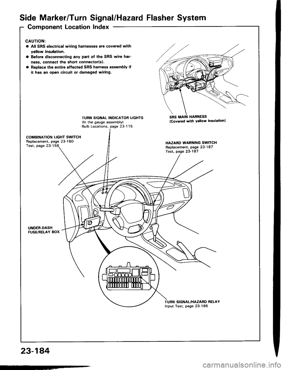
Side Marker/TurnSignal/Hazard Flasher System
Component LocationIndex
23-184
GAUTION:
a All SRS electrical wiring harnessos ar6 covered with
yellow insulation.
a Belor€ disconnocting any pan of the SRS wire har-
ngss, connoct the short connector{s).
a Rsplace tho 6ntir€ affect€d SRS harnoss sssembly il
it has an op€n cilcuit or damaged widng.
TURN SIGNAL INDICATOR LIGHTS(ln the gauge assembly)
SRS MAIN HARI{ESS(Cov.rod with Ysllow in3ulationl
Bulb Locations,23-115
COMBINATION LIGHT SWITCHReplacement, page 23-160HAZARD WARI{ING SWITCHReplacement, page 23-187Test, page 23-187
Test, page 23-1
UNDER-DASHFUSE/RELAY 8OX
TURN SIGNAL/HAZARO RELAYInput Test, page 23-186
-
Trending: fuel type, Park sensor wire, Remove trans, alternator circuit, sat nav, length, rocker arm
