HONDA INTEGRA 1994 4.G Workshop Manual
Manufacturer: HONDA, Model Year: 1994, Model line: INTEGRA, Model: HONDA INTEGRA 1994 4.GPages: 1413, PDF Size: 37.94 MB
Page 1311 of 1413
Replacement
CAUTIOI{:
a All SRS sloctdcal wiring harnossas are covered whhyollow insulatlon.
a B.tore disconnoctlng any part ot the SRS yyi16 h.r-nosa, connrct tho short connoctot(al.a Rsplaco th. onti.e !ffoct.d SRS hamoss a$ombly lfIt ha! an opon cilcuit or damagod wiring.
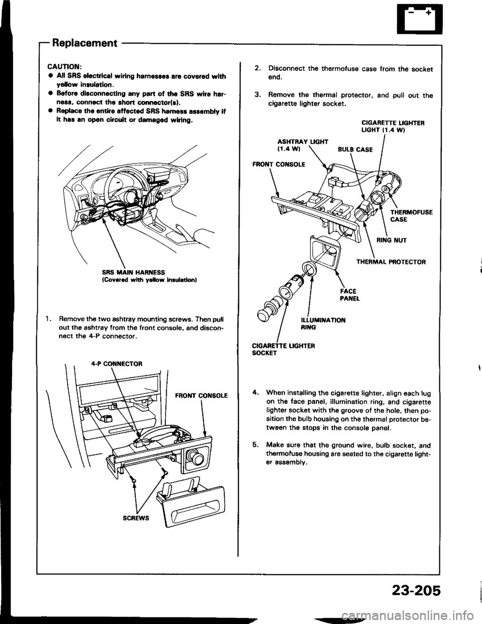
Remove the two ashtray mounting screws. Then pull
out the ashtray from the front console, and discon-
nect the 4-P conn€ctor,
scREws
.--
23-205
SOCKET
3.
Disconnect the thermotuse case from the socket
€no.
Remove the thermal protector. and pull out the
cigarette lighter socket.
CIGARETTE LIGHTENLTGHT (1.4 Wt
ASHTRAY LIGHT(r.4 wl
FROI{T CO|{SOLE
THERMOFUSECASE
4.
RI G NUT
THERMAL PAOTECTOR
When installing the cigarette lighter, align each lug
on the face panel, illumination ring, and cigarefte
lighter socket with the groove of the hole, then po-
sition the bulb housing on the thermal protector be-
tween the stops in the console panel.
Make sure that the ground wire, bulb socket, andthermofuse housing are seated to the cigarette light-
er assomblv.
Page 1312 of 1413
Rear Window Defogger
Component Location Index
CAUTION:
a All SRS olectrical wi ng ham€$6s are covoled with
y€llow insulation.
B6foro disconnocting any part of ths SRS wire har-
ness. connoct tho short connector(s).
Roplacs the ontire affectod SRS harness assombly if
it has an open circuit or damagcd wiring.
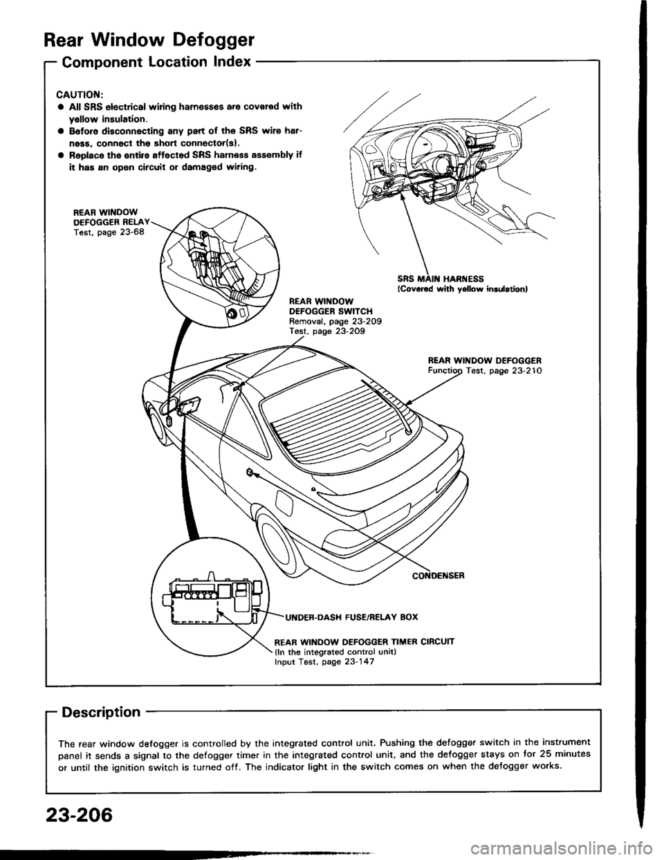
REAB WINDOWDEFOGGER RELAYTest, page 23-68
REAR WINDOWDEFOGGER SWITCHRemoval, page 23-209Test, page 23-2Og
REAR WINDOW DEFOGGERTest, page 23-210
UI{DER.DASH FUSE/RELAY BOX
REAR WINDOW DEFOGGER TIMER CIRCUIT
{ln the integrated control unil)fnput Test, page 23-147
SRS MAII{ HAR'{ESS
The rear window defogger is controlled by the integrated control unit, Pushing the defogger switch in the instrument
panel it sends a signal to the defogger time. in the integrated control unit, and the detogger stays on tor 25 minutes
or until the ignition switch is turned off. The indicator light in the switch comes on when the deJogger works.
23-206
Page 1313 of 1413
UNDER- HOOO FUSE,NE[AY 80X
B[K/GRN
I
[ql
t=l
tr
I
;ERI
I8LK
I
I:
H.tchback: G77Ssdan: G50
NOISECONDENSER
BLK/GRN
I
I'
23-207
Page 1314 of 1413
Rear Window Defogger
Troubleshooting
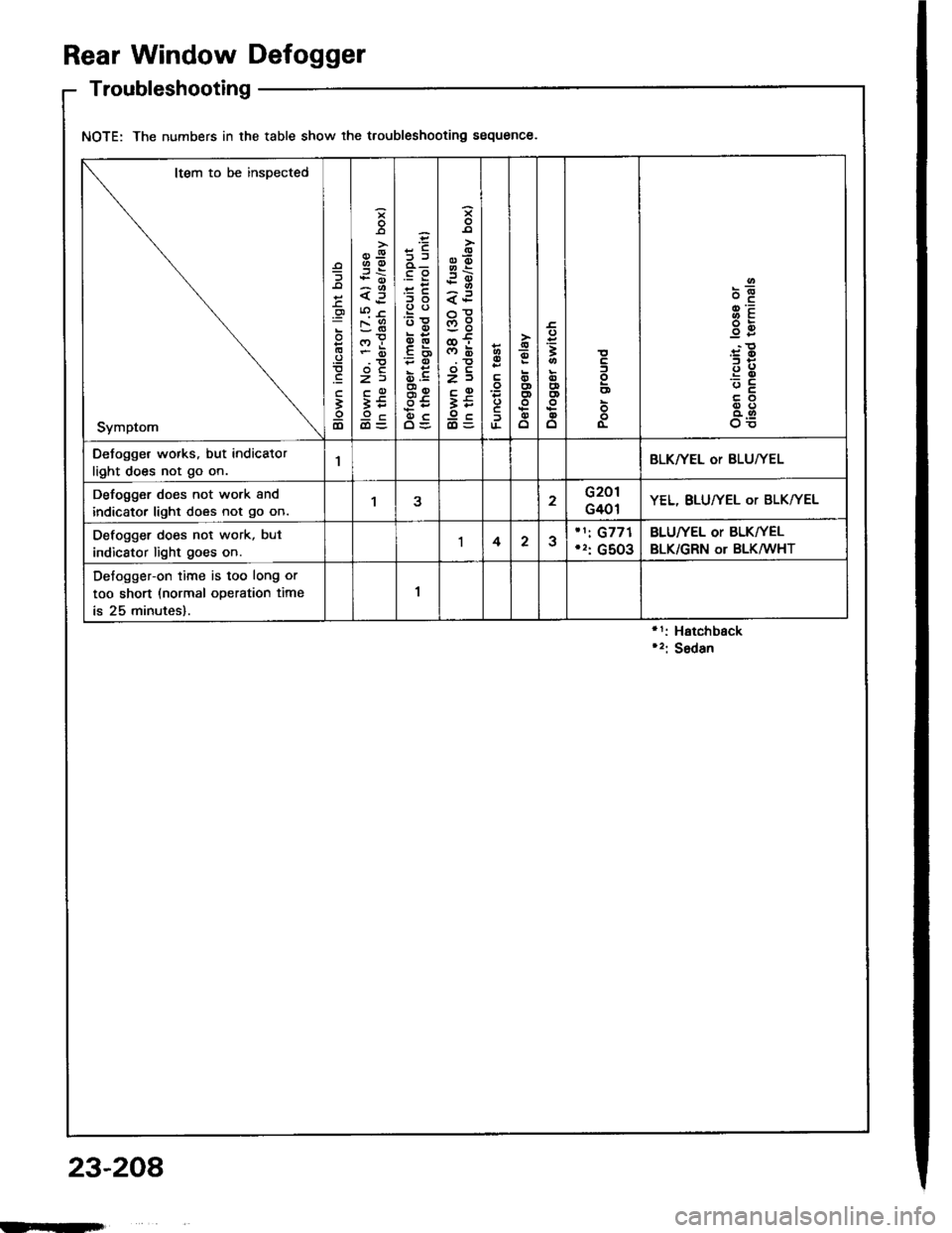
NOTE: The numbers in the table show the troubleshooting sequence.
'1: Hatchback'2: Sedan
Item to be inspected
Symptom
o
'
lD
*o--
zi
ii9c
.E
o.-
:E
go
.E6
5.
o0to9\cg
z)
;5
o
!
ooooo
=3
oEDo
o
o
oo-
@=
g8
oo
o5
Defogger works, but indicator
light does not go on.1BLKTYEL oT BLU/YEL
Defogger does not work and
indicator light does not go on.122G201
G401YEL, BLUfYEL or BLK/YEL
Defogger does not work, but
indicstor light goes on.1423'1i G771',: G5O3
BLU|YEL or BLKIYEL
BLK/GRN oT BLKMHT
Defogger-on time is too long or
too short (normal operation time
is 25 minutes).
1
23-208
IINIilfi
Page 1315 of 1413
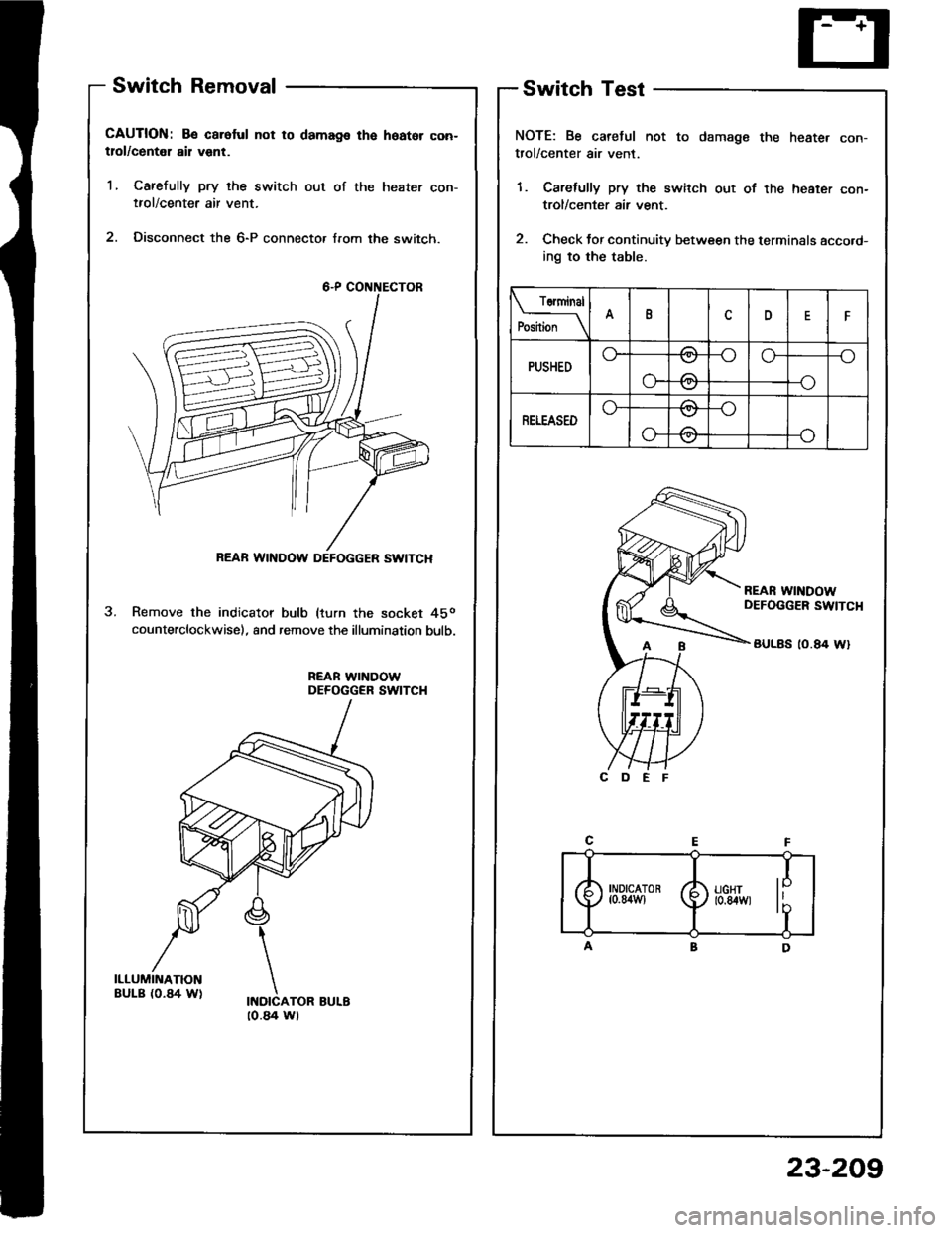
Switch Removal
CAUTION: Be caroful not to damags the hoator con-tlol/centel ail vent.
1, Carefully pry the switch out of the heater con-tfol/center air vent.
2. Disconnect the 6-P connecto, from the switch.
Remove the indicator bulb (turn the socket 45o
counterclockwise), and remove the illumination bulb.
REAR WINDOWDEFOGGER SWITCH
Switch Test
NOTE: Be caretul not to damage the heate. con-trol/center air vent.
1. Carefully pry the switch out of the heater con-
trol/center air vent.
2. Check tor continuity between the terminals acco.d-
ing to the table.
Torminal
P*il*__\IDF
PUSHEDo--oo-_o
o-
\../
-\-o
RETEASEDo-/\
o-
\:,,t
/:\\7
REAR WINDOW DEFOGGER SWITCH
[-4
I
) ll:g'", li'T
to.a4 wt
23-209
Page 1316 of 1413

Rear Window Defogger
Function Test
CAUTION: Be carelul not to scratch 01 damago ths
defogger wires with th€ tsster probe.
1 . Check for voltage between the positive terminal and
body ground with the ignition switch and the delog-
ger switch ON. There should be battery voltage.
a lf there is no voltage, check for
- laulty detogger relay.- faulty defogger switch.- faulty integrated control unit.- an open in the BLK/GRN wire
a lJ there is baftery voltage, go to step 2.
NEGATIVE TERMIiIALPOSITIVE TERMINAL
Turn the rear window detogger switch OFF, Check
for continuity between the negative terminal and
body ground.
a It there is no continuity, check to. an open in the
defogger ground wire.
a ll there is continuity, go to step 3.
Touch the voltmeter positive lead to the halfway
point of each defogger wire, and the negative lead
to the negative terminal.
There should be apptoximately 6 V with the ignition
switch and defogger switch ON.
a lf the voltage is as specified, the defogger wire
is OK.
a lf the voltage is not as specified. repai, the defog-
ger wire:
lf it is more than 6 V, look for the damage on
the negative half on the grid.
- lf it is less than 6 V. iook for the damage on
the positive half of the grid.
Defogger Wires Repair
NOTE: To make an eftective repair. the broken section
must be no longer than one inch.
1 . Lightly rub the area around the break with line steel
wool, then clean it with alcohol.
2. Carefullv mask above and below the broken portion
of the defogger wire with cellophane tape.
Using a small brush, apply a heavy coat of silver con-
ductive paint extending about 3 mm ( 1/8 inl on both
sides of the break. Allow 30 minutes to dry.
NOTE: Thoroughly mix the paint before use.
Check for continuity in the repaired wire.
Apply a second coat of paint in the same way.
it drv three hours betore removing the tape.
4.
OPEN
23-210
tLet
Page 1317 of 1413
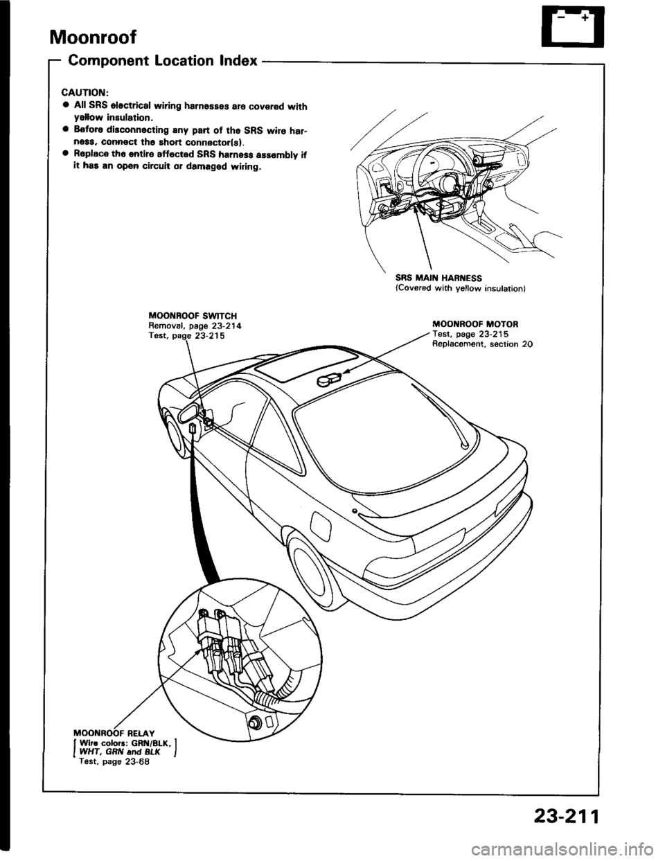
Moonroof
Gomponent Location lndex
a All SRS oloctrical wiring harnesses aro covared withyellow insulation,
a Eoforo disconnocting any part of tho SRS wire har-neaa, connoct th6 shon connector(sl.a Roplace th6 entire 8ff6cted SRS harness assombly ifit has an open circuit or damaged widng.
MOO BOOF SWTTCHRemov8l, page 23-214Test, page 23-215
SRS MAIN HARI{ESS{Covered with yellow insulation)
MOO ROOF MOTORTest, pag€ 23-215Replacoment, section 20
23-211
Page 1318 of 1413
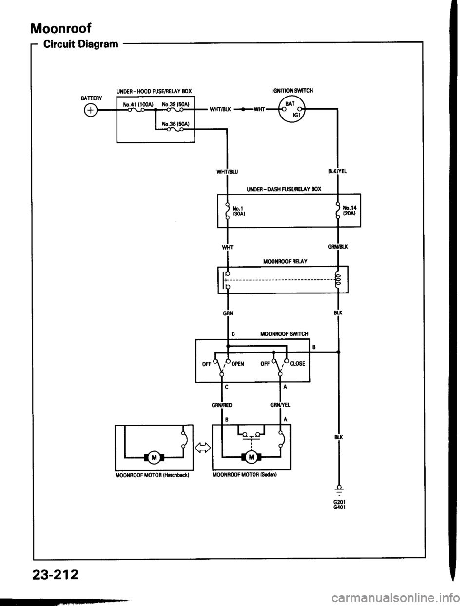
Moonroof
Circuit Diagram
lo
f"------------
- ---------
i|OoNRoOF MOf 0R H.rchb.cklMoO nOoF ttoton 6.ddl
23-212
-
Page 1319 of 1413
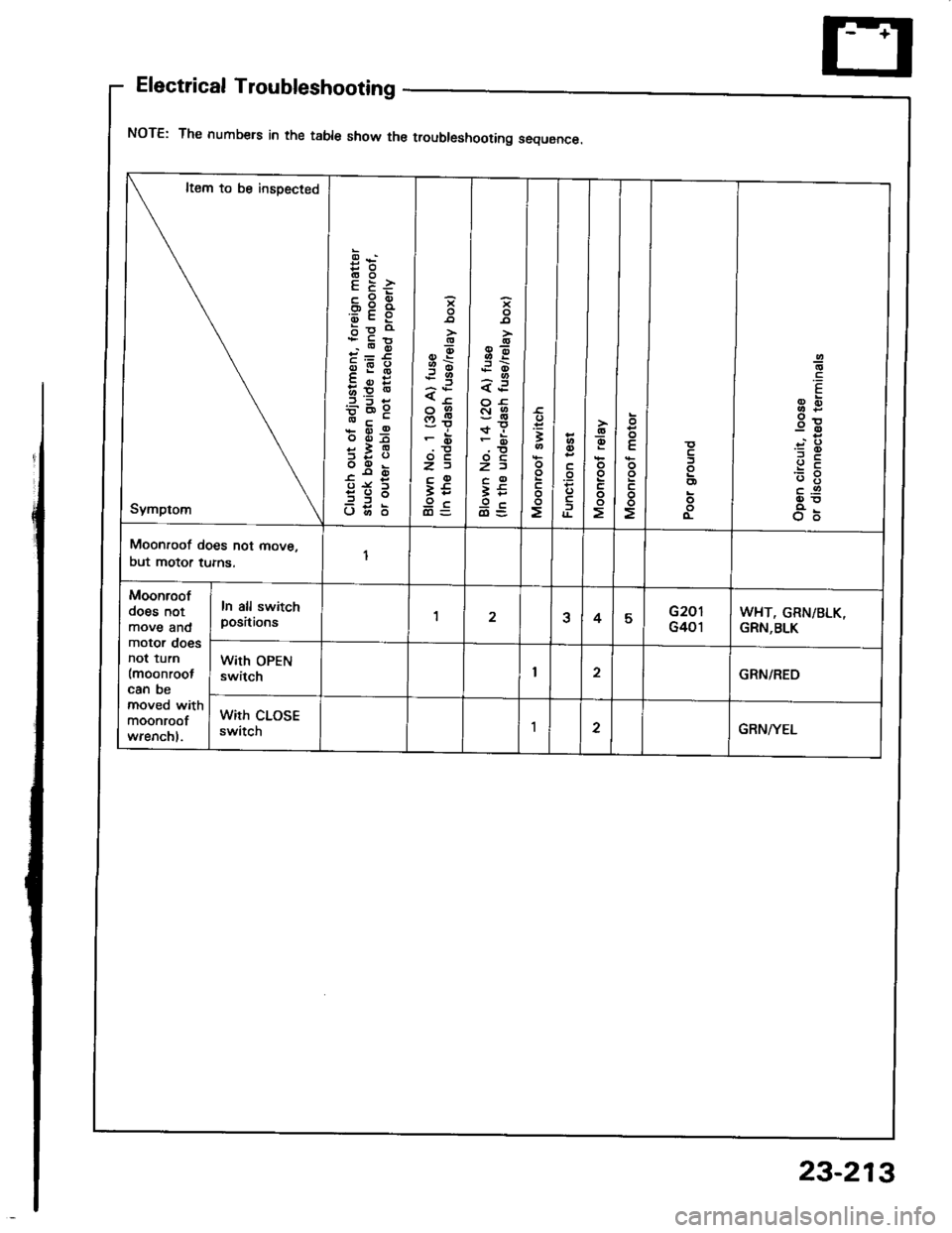
Electrical Troubleshooting
NOTE: The numbers in the table show the troubleshooting sequence.
It€m to be insoected
Symptom
es(!OE E:
FE3b9 o
.o6
;g:
oiSE
bE*
5:3
?t;:-=iE d
o66
-9-.9:t<
'r3
<-co9
F6
zac93t9cdl=
o
3E;o-
<€
3tr\fi
z)
t5
€t
3l.', l
>l
ct
go
o
oo
oo
oo
oo
oo
oo
.9
E-
3E
.::
a-g
o6
Moonroof does not move,
but motor tums.
Moonroof
does notmove andmotor doesnot tum
lmoonrootcan bemoved withmoonroof
wrenchl.
In all switchpositions1a45G201
G401WHT, GRN/BLK,GRN,BLK
With OPENswitchI2GRN/REO
with closEswitchI2GRN/YEL
23-213
Page 1320 of 1413
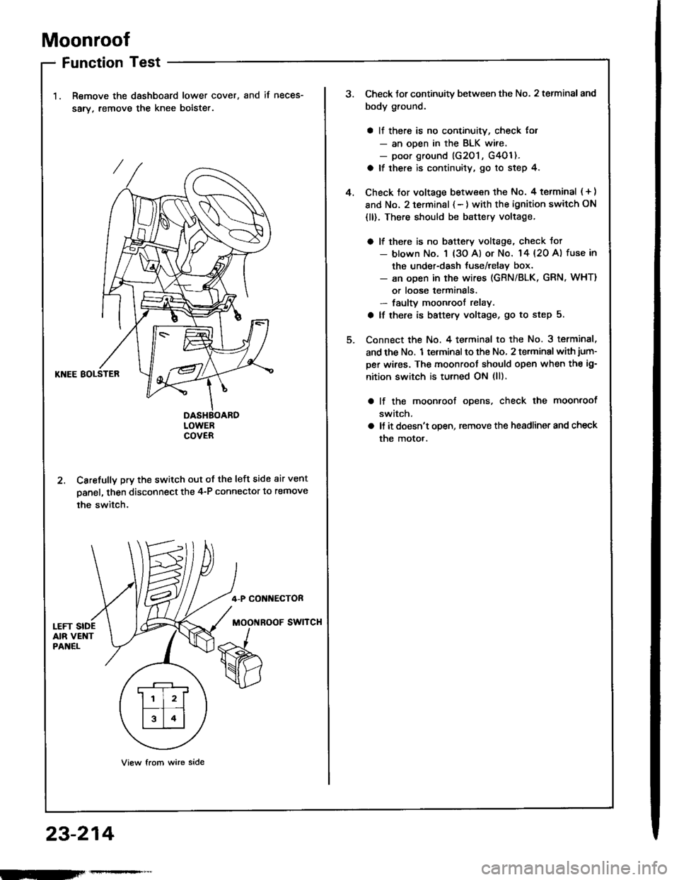
Moonroof
Function Test
Remove the dashboard lower cover,
sarv, remove the knee bolste..
and if neces-
KNEE BOLSTER
DASHBOARDLOWERCOVER
2. Carefully pry the switch out of the left side air vent
panel, then disconnect the 4-P connector to remove
the switch.
4-P CONI{ECTOR
MOOi{ROOF SWITCH
View from wire side
.r--r
ll l2lf--T� --t
l314l
23-214
Check Jor continuity between the No. 2 terminal and
body ground.
a ll there is no continuity, check for- an ooen in the BLK wire.- poor ground (G201 , G4Ol ).
a lf there is continuity, go to step 4.
Check tor voltage between the No. 4 terminal ( + )
and No. 2 terminsl { - ) with the ignition switch ON
{ll). There should be battery voltage.
a lf there is no baftery voltage, check tot- blown No. 1 (3o Al or No. 14 {20 A) fuse in
the under-dash tuse/relay box.- an open in the wires (GRN/BLK, GRN, WHT)
or loose terminals.- faulty moonroof relay.
a lf there is battery voltage, go to step 5.
Connect the No. 4 terminal to the No. 3 terminal,
and the No. 1 terminal to the No, 2 terminal with jum-
per wires. The moonroot should open when the ig-
nition switch is turned ON (ll).
lf the moonroof ooens, check the moonroof
switch,
ll it doesn't open, remove the headlinet and check
the motor.
4.