HONDA INTEGRA 1994 4.G Workshop Manual
INTEGRA 1994 4.G
HONDA
HONDA
https://www.carmanualsonline.info/img/13/6067/w960_6067-0.png
HONDA INTEGRA 1994 4.G Workshop Manual
Trending: trailer, system connectors, seat belt, Rings, valve cover, airbag off, maintenance schedule
Page 1301 of 1413
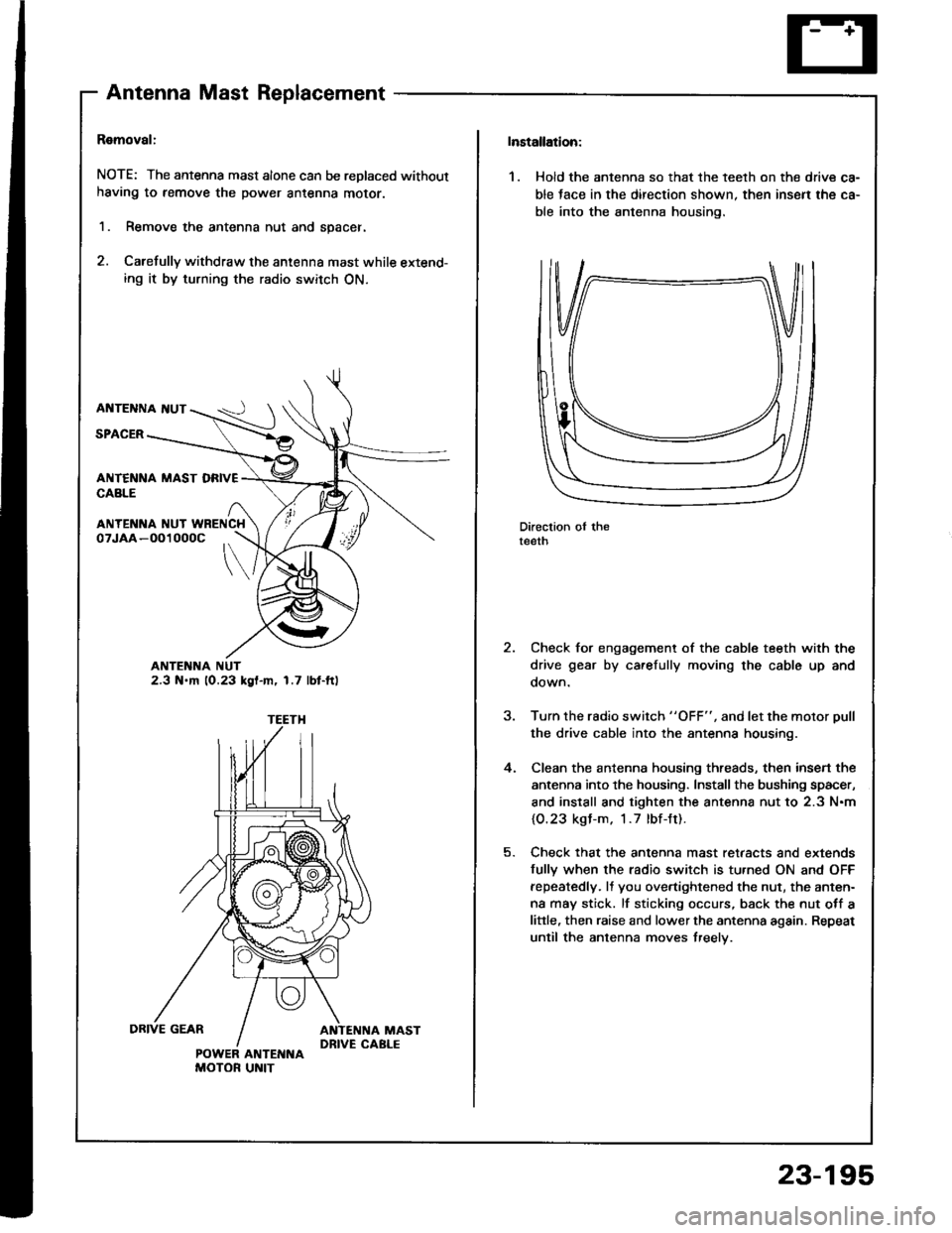
AntennaMastReplacement
Ramoval:
NOTE: The antenna mast alone can be replaced without
having to remove the power antenna moror.
1. Remove the antenna nut and spacer.
2. Carefully withdraw the antenna mast while extend-ing it by turning the radio switch ON.
AI{TENNA I{UT
SPACER
ANTENNA NUT2.3 N.m 10.23 kgl-m, 1.7 lbt-ft)
ANTENI{A NUT WRENCH
POWER ANTENNAMOTOR UNIT
Installation:
1. Hold the antenna so that the teelh on the drive ca-
ble tace in the direction shown. then insen the ca-
ble into the antenna housing.
Direction oI theteeth
Check for engagement of the cable teeth with the
drive gear by carefully moving the cable up and
oown.
Turn the rsdio switch "OFF", and let the motor Dull
the drive cable into the antenna housing.
Clean the antenna housing threads, then insen the
antenna into the housing. Install the bushing spacer,
and install and tighten the antenna nut to 2.3 N.m
{O.23 kgl-m. 1.7 lbf-Jt).
Check that the antenna mast retaacts and extends
fully when the radio switch is tu.ned ON and OFF
fepeatedly. It you overtightened the nut, the anten-
na may stick. lf sticking occurs, back the nut otf a
little, then raise and lower the antenna again. Repeat
until the antenna moves treelv.
,
4.
23-195
Page 1302 of 1413
Stereo Sound
Power Antenna
System
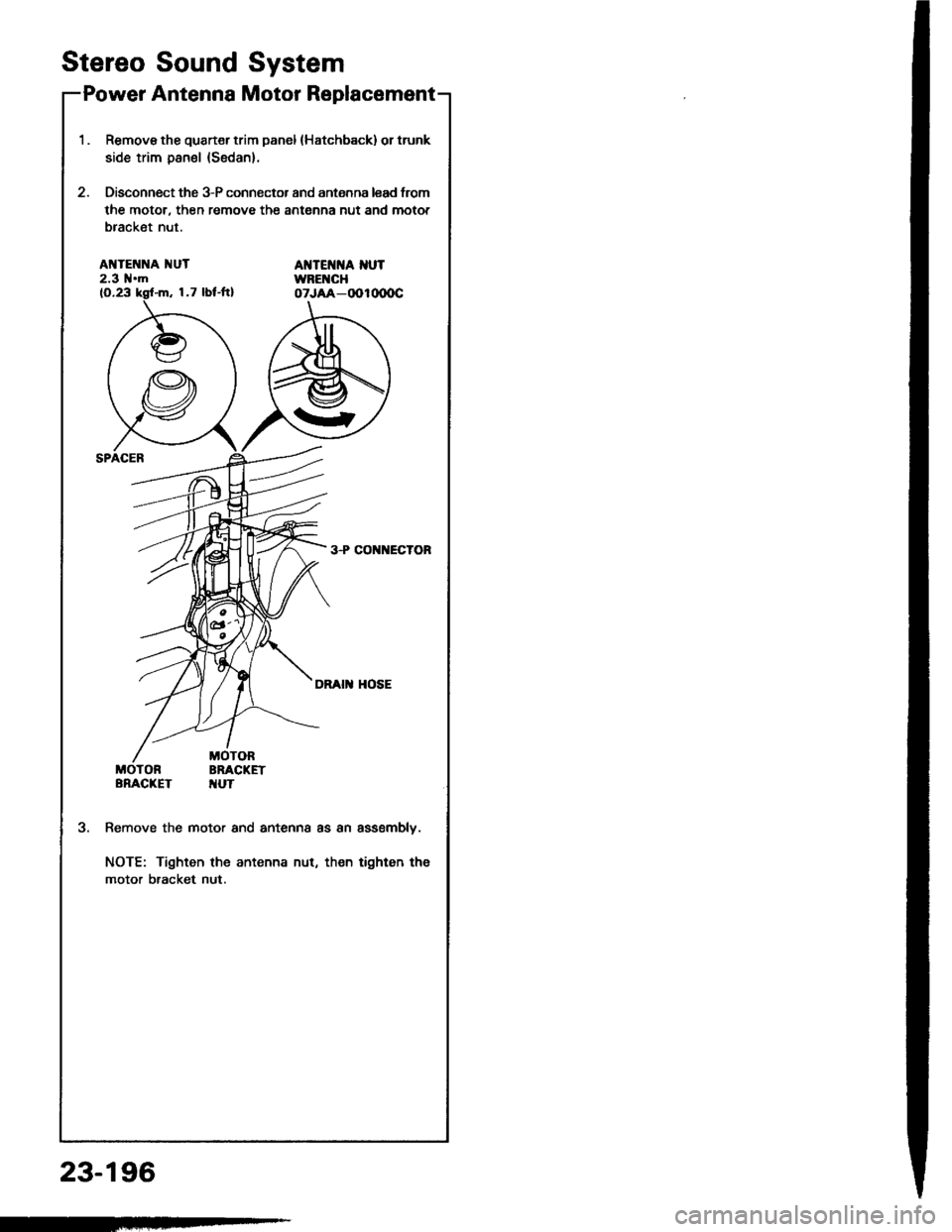
Motor Replacement
1.Remove tho quart€r trim panel (Hatchback) or trunk
side trim panel (Sedan).
Disconnect the 3-P connector and antenna lead trom
the motor, then remove the antenna nut and motor
bracket nut.
AI{TENNA 1{UT2.3 l{.mAT{TEI{]{A I{UTWBEI{CHoTJAA-OOlo(xrc
3+CO ECTOR
DRAI HOSE
MOTORBRACKETTUT
3.Remove the motor and antenna as an assemblv.
NOTE: Tighten the antenna nut, then tighten tha
motor bracket nut.
23-196
Page 1303 of 1413
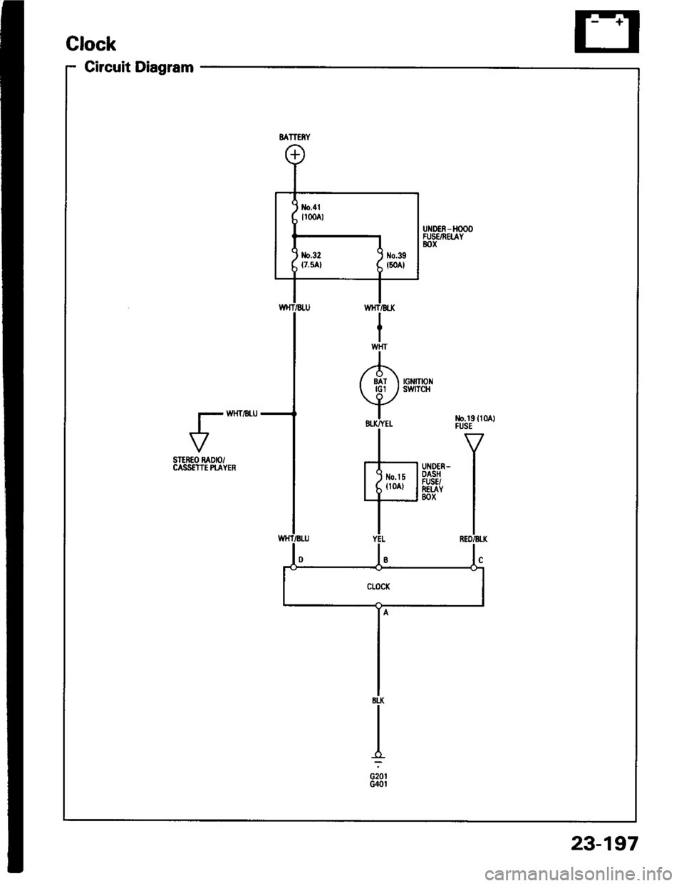
Circuit Diagram
VSTEREO RADIO/CASS€TIE PI-AYER
23-197
Page 1304 of 1413
Clock
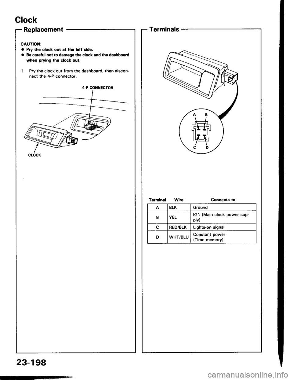
Replacement
CAUTION:
a Pry th6 clock out at th€ left sido,
a Be carsful not to damage the clock and the dashboE d
whon prying the clock out.
1. Pry the clock out from the dashboard, then discon-
nect the 4-P connector.
4-P COI{NECTOR
CLOCK
23-198
Terminals
Torminal WiroConnecta to
ABLKGround
YELplv){Main clock power sup-
RED/BLKLights-on signal
DWHT/BLUConstant power
(Time memory)
Page 1305 of 1413
Horn
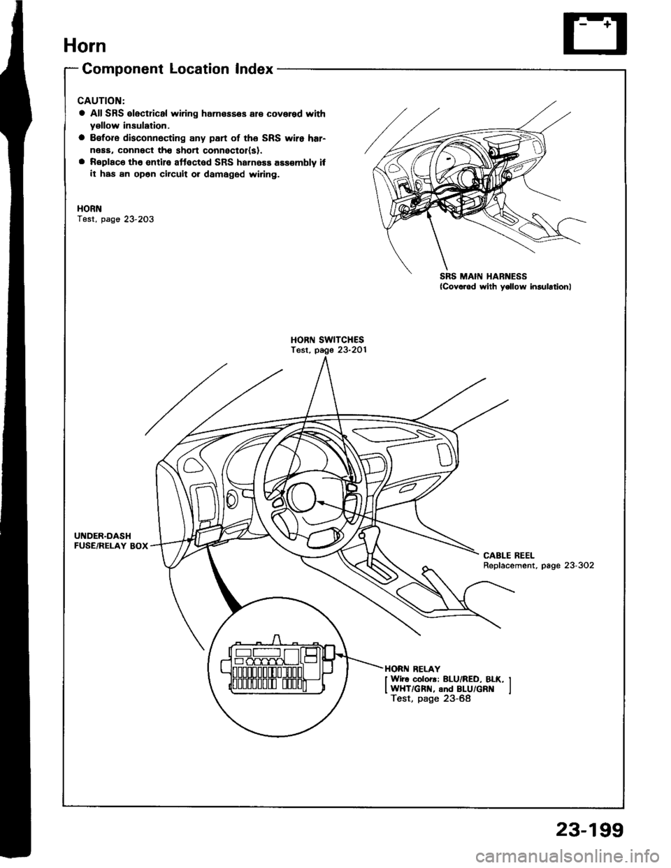
Component Location Index
CAUTION:
a All SRS €lectricsl wiring harnesses al€ covered with
yellow insulation.
a B€fore disconnecting any part of the SRS wiro har-
neaa, connect tho short connectol(sl.a Replaco the entire aftected SRS harness assembly ifit haa an open circuit ot damaged wiring.
HORNTest, page 23'2O3
HORN SWITCHESTest, pago 23-2Ol
UNDER.DASHFUSE/RELAY BOXCABLE REELRepfacement, page 23-302
HORN RELAY
I Wiro coloB: BLU/RED, BLK, IIWHT/GRN, and BLU/GR lTest, page 23-68
{Covo.ed wiih yollow insulationl
<------\-\----.....=
23-199
Page 1306 of 1413
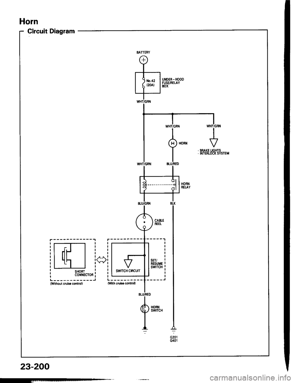
Horn
Circuit Diagram
------------.,1
r-T-l
lll- l
l1'l I
SHORTc0ill{EcToR
()
L------------JWrthout crub6 conlrol,
23-200
MTTERY
Page 1307 of 1413
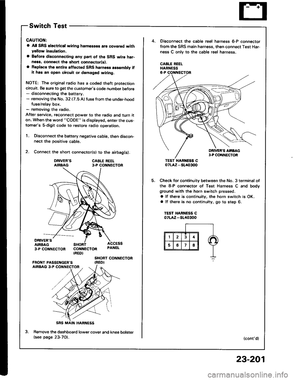
Switch Test
CAUTION:
a All SRS el6ctrical wiring harnossos are covarod withyellow inaulation.
a Beforo disconnecting any pan ot the SRS wire har-neaa, connoct ths short connector(s).a Roplace the entil€ afloctod SRS harne$ a$6mbly ifit has an open circuit or dsmagad wlring.
NOTE; The original radio has a coded theft protection
circuit. Be sure to get the customer's code number before- disconnecting the battery.- removing the No. 32 {7.5 A) fuse lrom the under-hoodtuse/relav box.- removing the radio.
After service, reconnect power to the radio and turn iton. When the word "CODE" is displayed, enter the cus-tomer's 5-digit code to restore radio operation.
1. Disconnect the battery negative cable, then discon-nect the positive cable.
2. Connect the short connector(sl to the airbag(sl.
DRIVER'SAIRBAGCABLE REEL3.P CO NECTOR
DRIVER'SAIRBAG3-PCO'TNECTOR COI{NECTOR{RED}
ACCESSPAI{EL
SHORT CONTIECTOR{REO}
Remove the dashboatd lower cover and kne€(see page 23-701.
5.
4. Disconnect the cable reel harness 6-P connector
from the SRS main harness, then connect Test Har-
ness C onlv to the cable reel harness.
CABLE REELHARNESS
TEST HAR ESS CoTLAz - SL/l{,3OO
Check for continuity between the No, 3 terminal ot
the 8-P connector of Test Harness C and body
ground with the horn switch pressed.
a lf there is continuity, the horn switch is OK.a lf there is no continuity, go to step 6.
TEST HARNESS COTLAZ-SI/I()3OO
(cont'd)
bolster
23-201
Page 1308 of 1413
Horn
SwitchTest(cont'd)
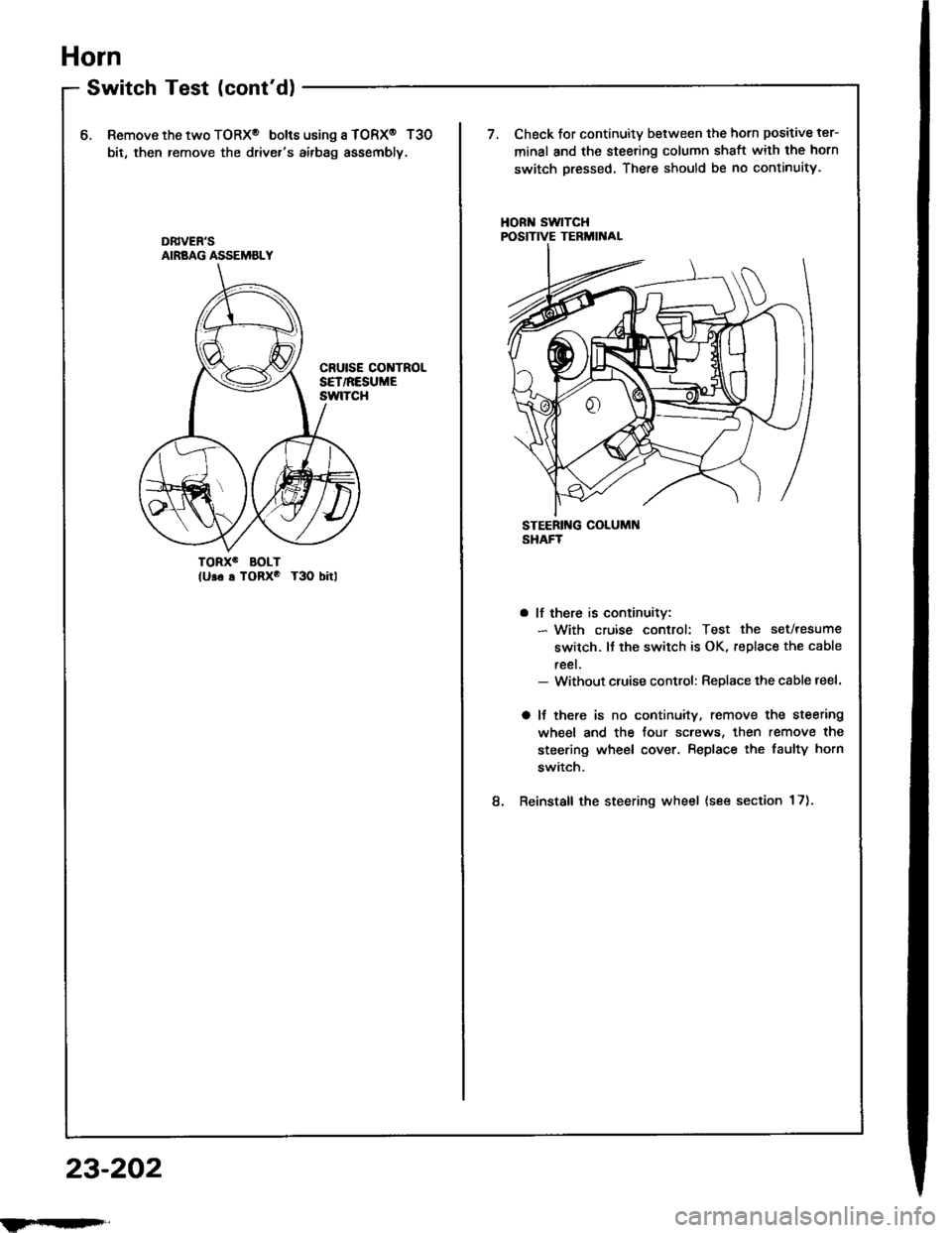
6.Remove the two TORX@ bolt6 using a TORX@ T30
bit, then remove the driver's airbag assembly.
Check for continuity between the horn positive ter-
minal and the steering column shaft with the horn
switch pressed, There should be no continuity.
HORN SwlTCHPOSITIVE TERMIITAL
TORXO BOLT(U!6 s TORxo T3O bitl
8.
a lf there is continuitv:- With cruise control: Test the set/resume
switch. lJ the switch is OK, replace the cable
reel.- Without cluise control: Replace the cable reel.
a lJ there is no continuity. remove the steering
wheel and the four screws, then remove the
steering wheel cover. Replace the faulty horn
switch.
Reinstall the steering wheel {see section 17).
DB|vEN'SAIRBAG ASSEMBLY
23-202
ilFrrI|qFrl"
Page 1309 of 1413
MOUNTI G AOLT
t.
2.
5.
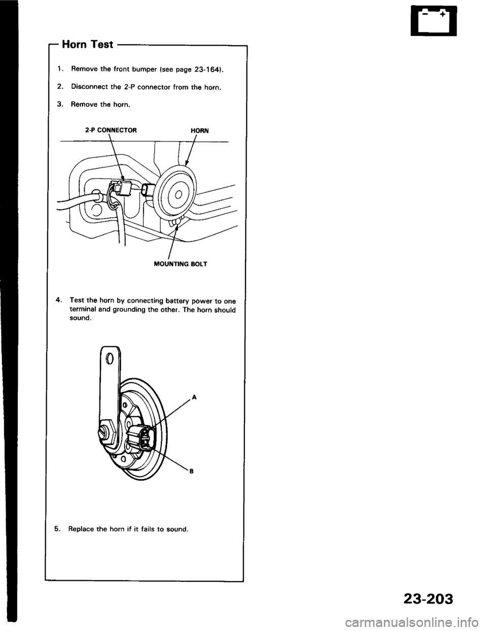
Horn Test
Remove the front bumper (see page 23-164).
Disconn€ct the 2-P connector from the hofn.
Remove the horn.
2-P COt{t{ECTOB
4. Test the horn by connecting battery power to oneterminsl and grounding the other, The horn shouldsound.
5. Reolace the horn if it fails to sound.
23-203
Page 1310 of 1413
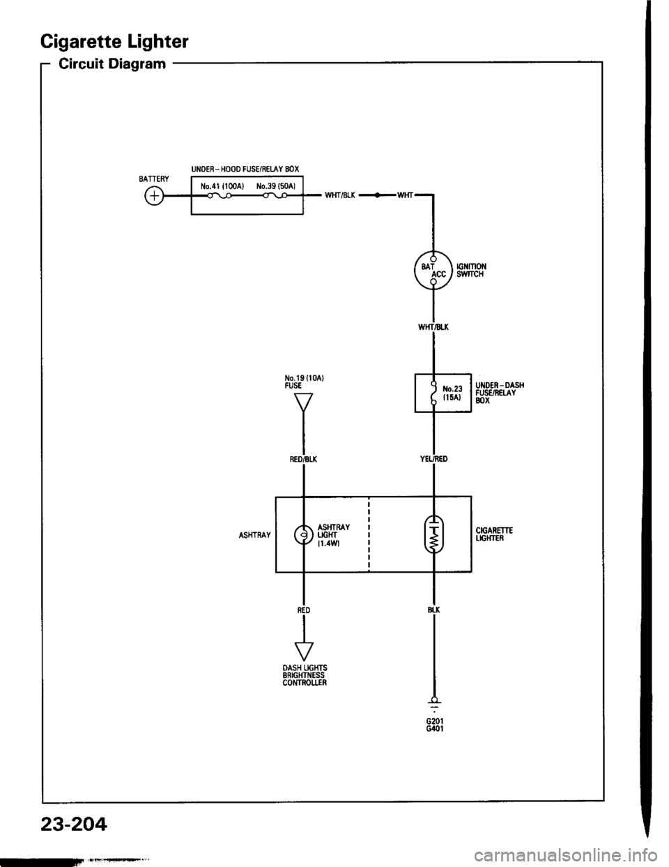
Cigarette Lighter
Circuit Diagtam
No.tg ll0AlFUSEUIIOER- DASHFUSE/N€[AYBOX
BI.K
G20tGilol
UNOER-HOOD FUSE/RELAY BOX
23-204
-iFn't'+rF*."'
Trending: driver door panel, boot lid, maintenance schedule, trunk trim, lower arm, fast idle thermo valve, battery

