HONDA INTEGRA 1994 4.G Workshop Manual
Manufacturer: HONDA, Model Year: 1994, Model line: INTEGRA, Model: HONDA INTEGRA 1994 4.GPages: 1413, PDF Size: 37.94 MB
Page 1261 of 1413
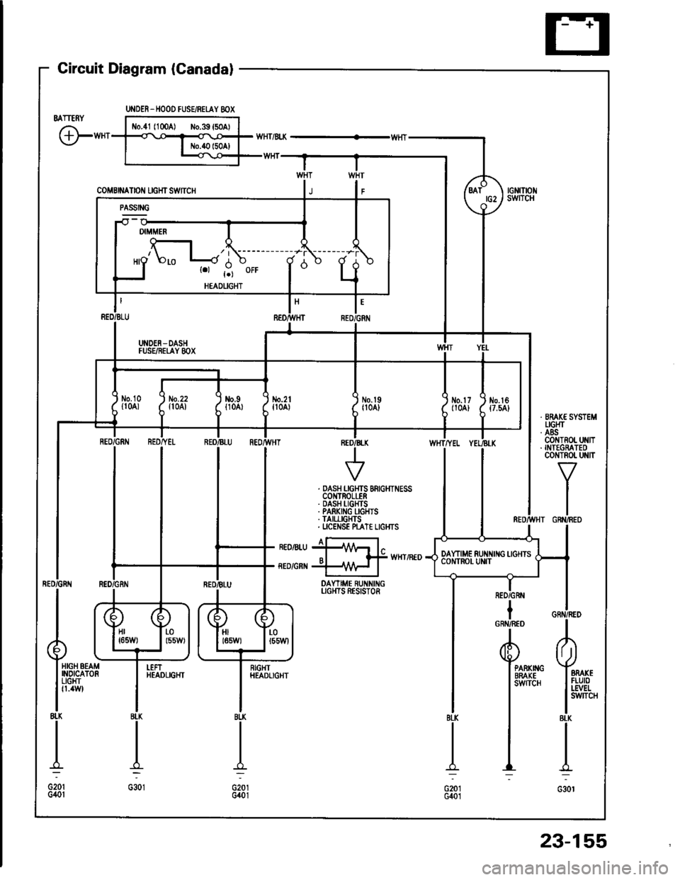
Gircuit Diagram (Canadal
BATTERY
G"*
UNOER_HOOD FUSEiRETAY 8OX
coMBrNAtor{ rcHrswnc
-il w
| '.=r" I
ll'L I I
I I *o\." l-'li' ;- ;j
I LI
"- r.r-,9 "orr
I
d "
L
RED/BLU REO/}VHT RED,ll
I UNDEN-DASH II FUSEiIEI,AY 8OX I
tl
L-J
t'GRN
/d\BATtG2\9-l
rGNrTrot{swITcH
No.2lfl0A)\I
No.l9|l04]Jm.tr (
t10A) ttt
I
No.l6{7.54}
tl
i,"#
llrrff li'rrt,
RED/GRtIIBLU REOr'TVHTINED/B
V
WHTTYEL
. DASH LGHTS BRIGHTNESSCOI{TROLLER. DASH I-IGHTS. PARKING I-GHIS. TAII,LIGHTS. UCENSE N"AT€ LIGI{TS
I a-rneonru jllA/Vr l"o I f# wxrintoRED/GRI{ +\{H I
DAYTIME RUNNINGUGI{TS RESISTOR
IRED/GRN
Hr I r-01651,1/) | l55W)HIt85W)LOt55Wl
HIGH BEAMINOICATORUGHTfl.4W
I
RIGHTHEADLIGHTPARKIIIGBRAKEsw{TcH
23-155
Page 1262 of 1413

Lighting System
Daytime Running Lights Control Unit Input Test (Canada)
CAUTION:
a All SRS eloc{dcal wi ng harn€sses are covelod with
yollow insulation.
a Boforo dbconnocting any psrt of the SRS wir€ h8r-
noss, connoct tho shon connector(s).
a Roplace the entire affected SRS harness assombly it
it has an opon Gilcuit or damagod wifng.
1 . Remove the dashboard lower cover and knee bolster.
2. Disconnect the connectors from the daytime running
lights control unit.
3. Insoect the connectof and socket terminals to be
sure they are all making good contact.
a ll the terminals are bent, loose or coroded, repair
them as necessary. and recheck the system,
a lf the terminals look OK, make the following in-
put tests at the connector,- lf any test indicates a problem, find and cor-
.ect the cause, then recheck the system.- ll allthe input tests prove OK, the control unit
must be taulty; replace if
4-P CONI{ECTOR
WHT/RED
YEL/ALK
8-P CONNECTOR
GRN/RED
WHTA'EL
23-156
View from wire sideVi6w from ware side
RED/GRI{
Page 1263 of 1413
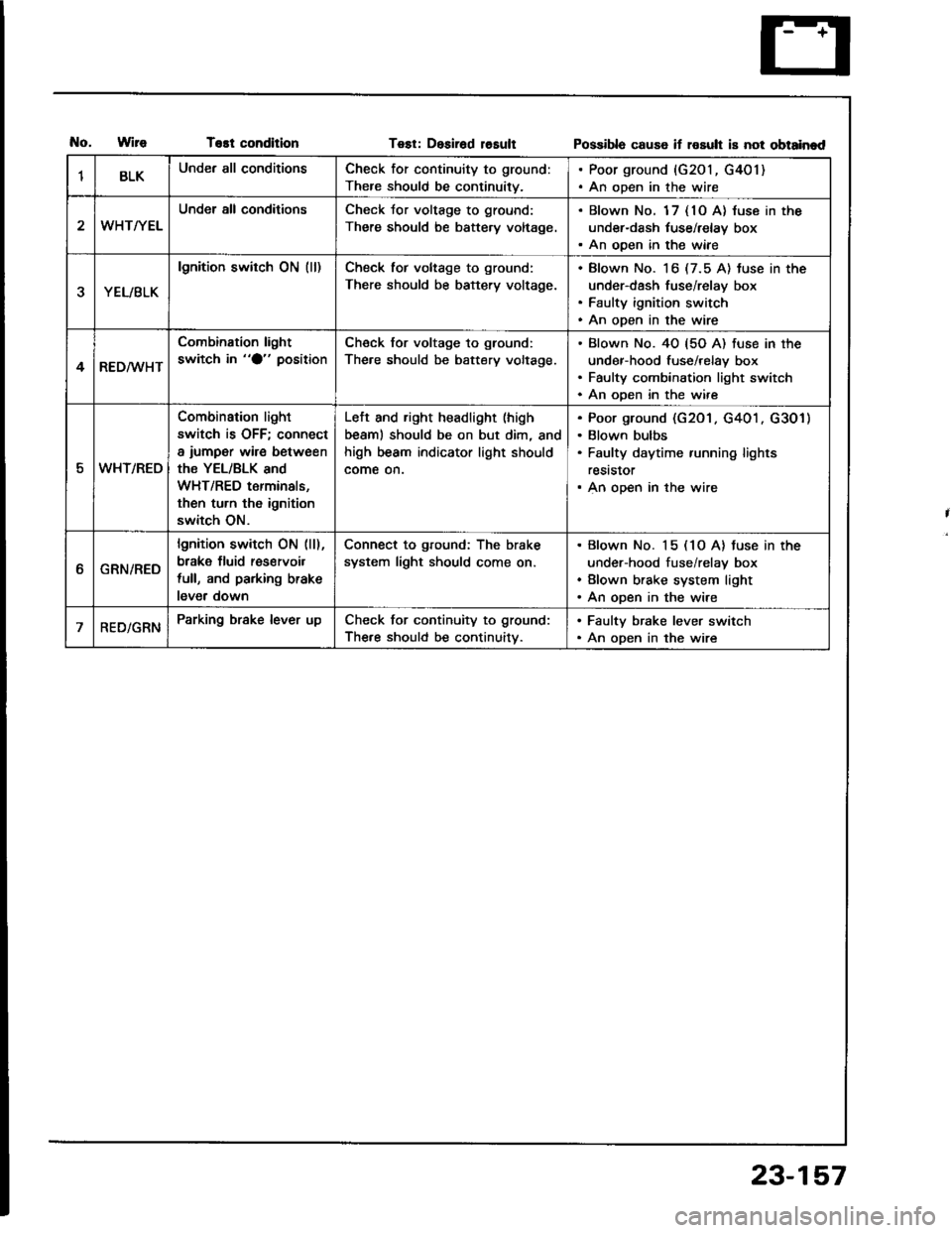
T€st conditionTest: Desirad losultPossibla cause if rosult is not obtainad
1BLKUnder all conditionsCheck for continuity to ground:
There should be continuity.
. Poor ground {G201, G401). An open in the wire
WHT/YEL
Under all conditionsCheck Jor voltage to ground:
There should be battery voltage.
. Blown No. 1 7 { 10 A} luse in the
under-dash tuse/relay box. An ooen in the wiae
YEL/BLK
lgnition switch ON (ll)Check tor voltage to ground:
There should be battery voltage.
Blown No. 16 (7.5 A) tuse in the
under-dash fuse/relay box
Faulty ignition switch
An open in the wire
4RED/WHT
Combination light
switch in "O" positionCheck for voltage to ground:
The.e should be battery voltage.
Blown No. 40 {5O A) fuse in the
under-hood fuse/relay box
Faulty combination light switch
An ooen in the wire
5WHT/REO
Combination light
switch is OFF; connect
a iumper wire between
the YEL/BLK and
WHT/RED terminals,
then turn th6 ignition
switch ON.
Left and right headlight (high
beaml should be on but dim, and
high beam indicator light should
come on.
Poor ground (G201 . G401 . G301)
Blown bulbs
Faulty daytime running lights
reststor
An open in the wire
ttGRN/RED
lgnition switch ON (ll),
brake fluid res€rvoil
full, and parking brake
lever down
Connect to ground: The brake
system light should come on.
Blown No. 15 (1O A) tuse in the
under-hood fuse/relay box
Blown brake system light
An open in the wire
RED/GRNParking brake lever upCheck for continuity to ground:
The.e should be continuitv.
. Faulty brake lever switch. An open in the wire
23-157
Page 1264 of 1413
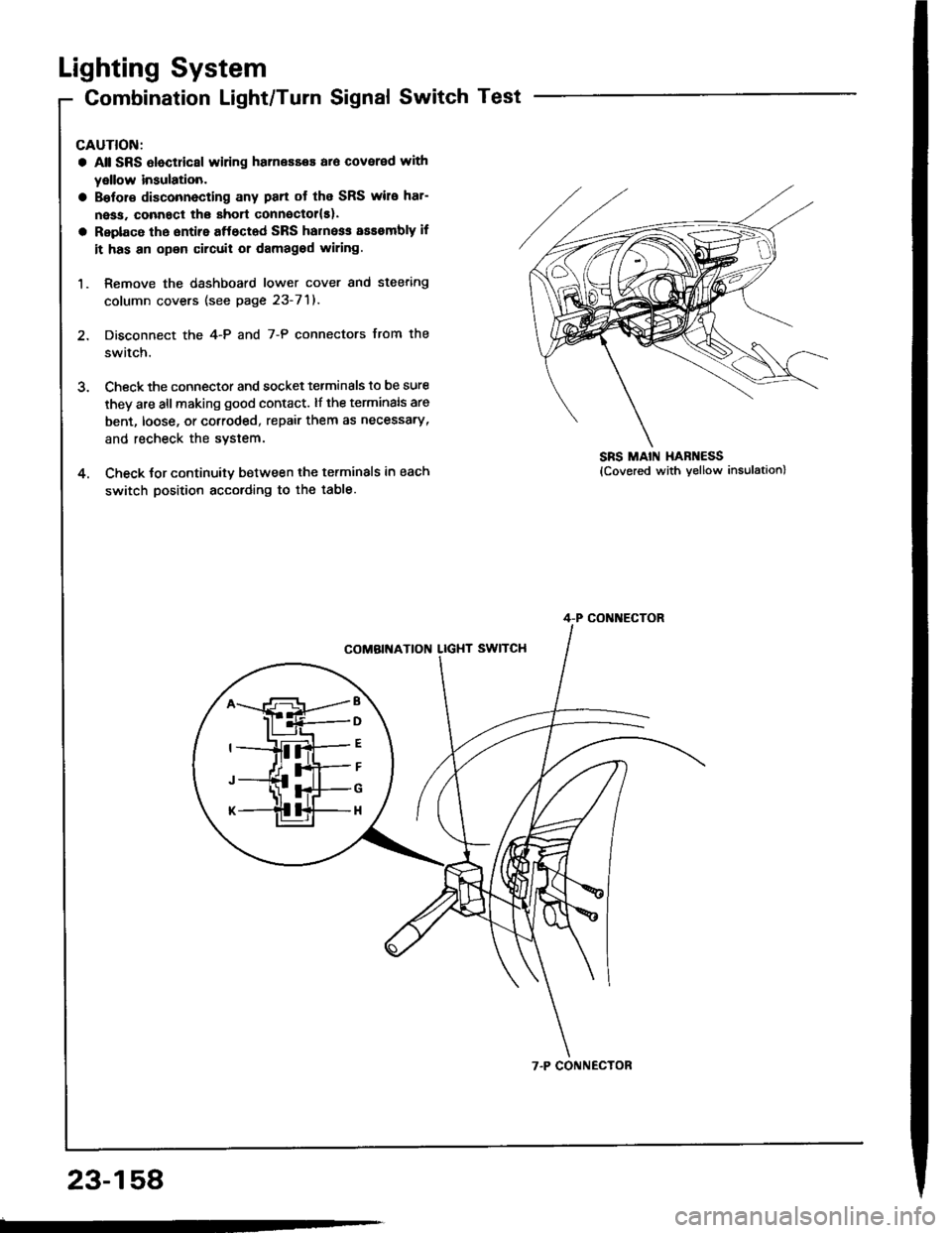
Lighting System
Combination Light/Turn Signal Switch Test
CAUTION:
a Atl SRS Oloctricsl wiring harnesses ar6 covered with
yellow insulation.
a Bslor€ disconnecting any pan ot the SRS wire har-
ness, connact the short connsctollsl.
a Replace the sntire aftectad SRS harne$ assembly if
it has an opon circuit or damagod wiring.
1. Remove the dashboard lower cover and steering
column covers (see page 23-71).
2. Disconnect the 4-P and 7-P connectors from the
switch.
3. Check the connector and socket tetminals to be sure
they are all making good contact. lf the terminals are
bent, loose, or cotroded, repair them as necessary,
and recheck the system.
4. Check tor continuitv between the terminals in each
switch position according to the table.
SRS MAIN HAR ESS
B
D
G
H
4-P CONI{ECTOR
7.P CONNECTOR
23-158
Page 1265 of 1413
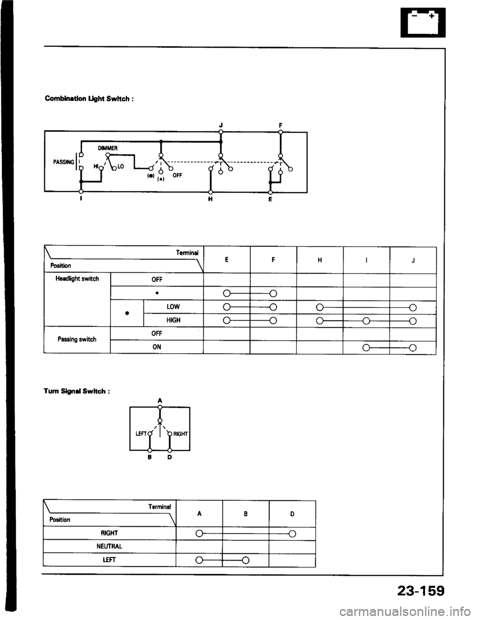
ComHnrtlon llght Swhch :
Tum Slgn.l Swhch :
Position
TErminslEt-HJ
Hsrdfight stvitchOFF
1J
aL0wn--oo
HIGHo
Passing switchOFF
ONGo
/t\RIGHT
Position
TsrminalA8D
RIGHTo-o
NEIIIMT
uFro(J
23-15,9
Page 1266 of 1413
Lighting System
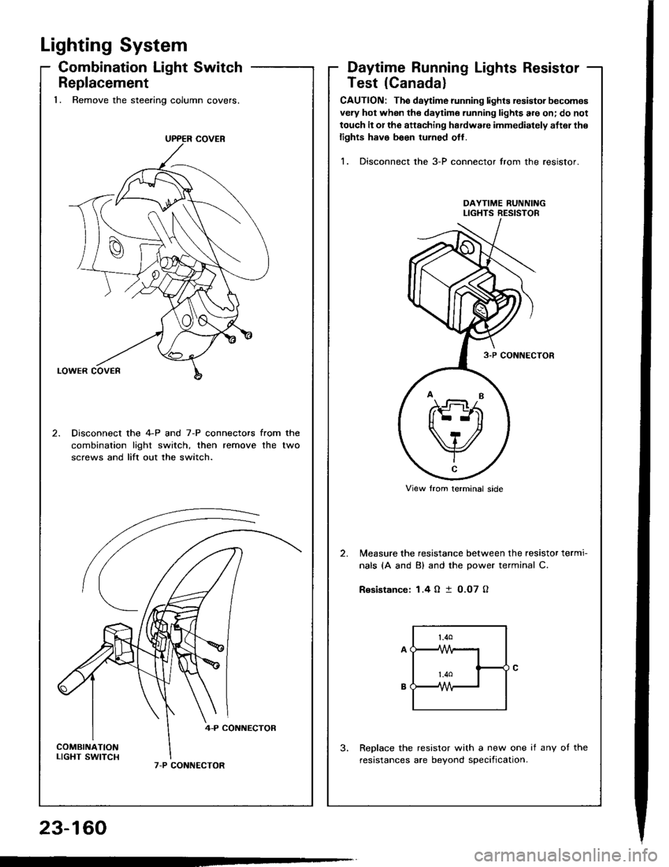
Combination Light Switch
Replacement'1. Remove the steering column covers.
Disconnect the 4-P and 7-P connectors from the
combination lighr switch, then remove the two
screws and lift out the switch.
Daytime Running Lights Resistor
UPP€R COVER
Test lCanada)
CAUTION: The daytime running lights resistor becomas
vely hot when the daytime running lights are on; do not
touch it or the attaching hardware immediately aftel th€
lights h8ve b€en turned otf.
1. Disconnect the 3-P connector from the resistor.
DAYTIME RUNNINGLIGHTS RESISTOR
Measure the resistance between the resistor termi-
nals (A and B) and the Dower terminal C.
R€sistance: 1.4 O I O.O7 O
Replace the resistor with a new one if any ot the
resistances are bevond soecification.
?nd
V-c
View trom lerminal side
23-160
Page 1267 of 1413
Headlight
Description
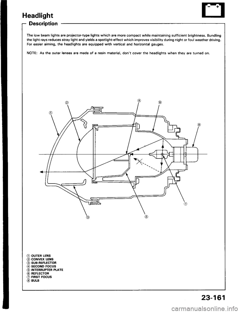
The low beam lights are proiector-type lights which are more compact while maintaining sufficient brightness. Bundling
the light rays reduces stray light and yields a spotlight-effect which improves visibility during night or foul weather driving.
For easier aiming, the headlights are equipped with vertical and horizontal gauges.
NOTE: As the oute. lenses are made oI a resin material, don't cover the headlights when they a.e turned on.
OUTER LENScoNvEx LEI{SSUB-REFLECTORsEcoND FOCUSINTERRUPTER PLATEREFLECTOBFIRST FOCUSBULB
23-161
Page 1268 of 1413
Headlight
Adjustment
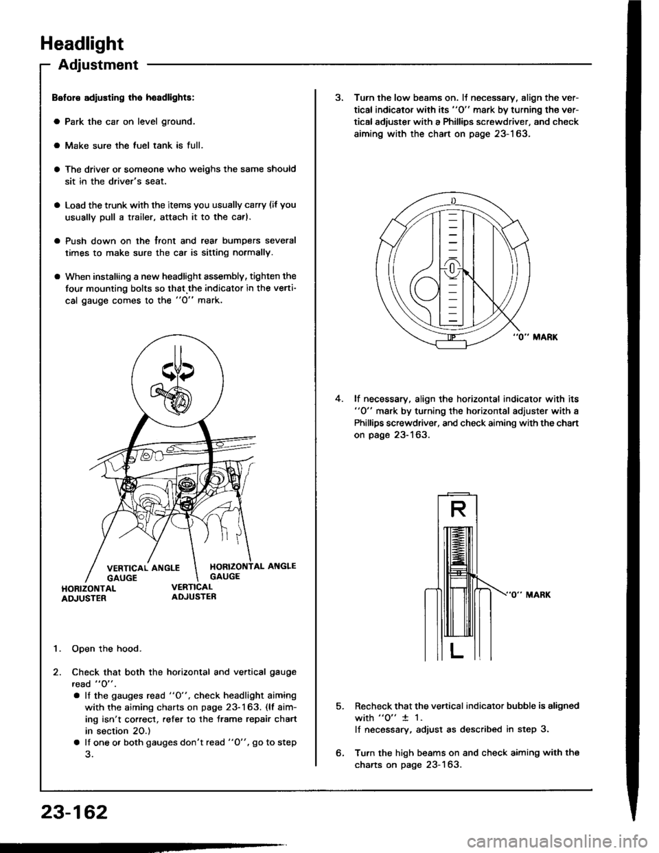
Belol€ adiusting lha hoadlights:
a Park the car on level ground.
a Make sure the luel tank is full.
a The driver or someone who weighs the same should
sit in the driver's seat.
a Load the trunk with the items you usually carry (if you
usually pull a trailer, attach it to the carl.
a Push down on the tront and rear bumDers several
times to make sure the car is sitting normally.
a When installing a new headlight assembly, tighten the
four mounting bolts so that.the indicator in the verti-
cal gauge comes to the "O" mark.
1. Open the hood.
2. Check that both the horizontal and vertical gauge
read " O" .
. lf the gauges rcad "O", check headlight aiming
with the aiming charts on page 23-163. (lf aim-
ing isn't correct, refer to the trame repair chart
in section 20.)
a lf one o. both gauges don't read "O". go to step
23-162
3. Turn the low beams on. lJ necessary, align the ver-
tical indicator with its "O" mark by turning the ver-
tical adiuster with a Phillips screwdriver, and check
aiming with the chart on page 23-163.
lf necessary, align the horizontal indicator with its"0" mark by turning the horizontal adjuster with a
Phillips screwdriver, and check aiming with the chart
on page 23-163.
4.
5.Recheck that the vertical indicator bubble is aligned
with "o" 1 1.
lf necsssary, adjust as described in step 3.
Turn the high beams on and check aiming with the
charts on page 23-163.
Page 1269 of 1413
Measurements (Standardl:
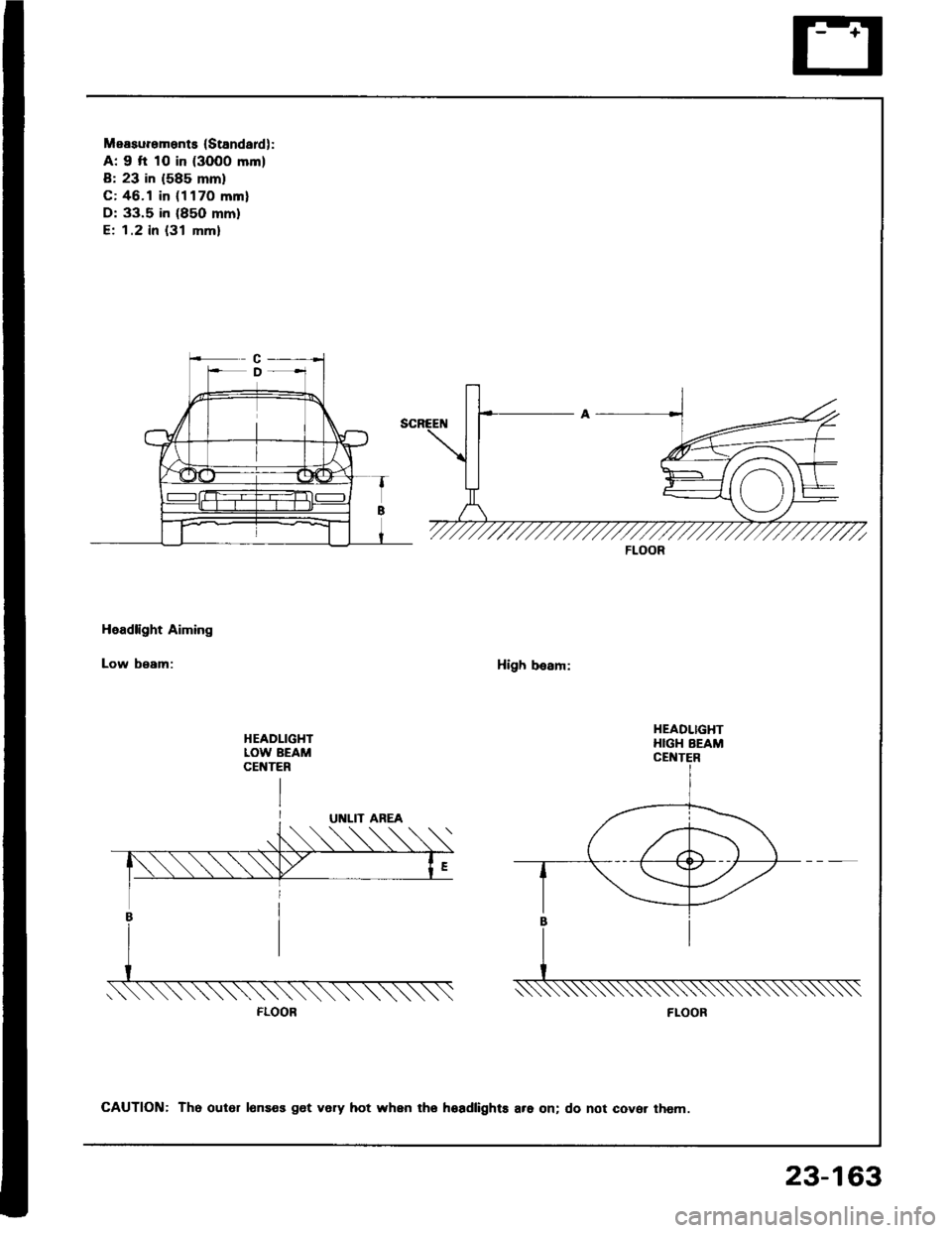
A: 9 fi 10 in (3000 mm)
B: 23 in (585 mm)
C: 46.1 in (1170 mml
D: 33.5 in (85O mm)
E; 1.2 in {31 mm}
Headlight Aiming
Low beam:High besm:
HEADLIGHTLOW BEAMCEt{TER
FLOOR
HEADLIGHTHIGH BEAM
FLOOR
CAUTION: Th6 out6r lonses get very hot when tho hoadlights are on; do not cover them.
23-163
Page 1270 of 1413
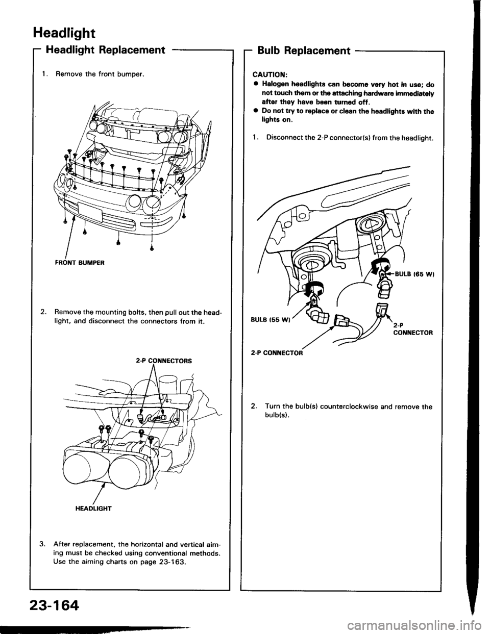
Headlight
Headlight Replacement
1. Remove the front bumoer.
Remove the mounting bolts, then pullout the head-
light, and disconnect the connectors from it.
Afte. replacement. the horizontal and vertical aim-ing must be checked using conventional methods,
Use the aiming charts on page 23-163.
Bulb Replacement
CAUTION:
a Halogon headlights can bocomo voly hot in usa; do
not touc$ them or tho attaching hardware imm6diatoly
arter they hava been lurnod off,a Do not try to roplace or cl6an the headlights with thelights on.
I . Oisconnect the 2-P connector(s) from the headlight.
coNlrtEcToR
2. Turn the bulb(s) counterclockwise and remove the
bulb(s).
FRONT BUMP€R
HEADLIGHT
23-164