Oil HONDA INTEGRA 1994 4.G Workshop Manual
[x] Cancel search | Manufacturer: HONDA, Model Year: 1994, Model line: INTEGRA, Model: HONDA INTEGRA 1994 4.GPages: 1413, PDF Size: 37.94 MB
Page 462 of 1413
Electrical Troubleshooting
Troubleshooting Flowchart (cont'd)
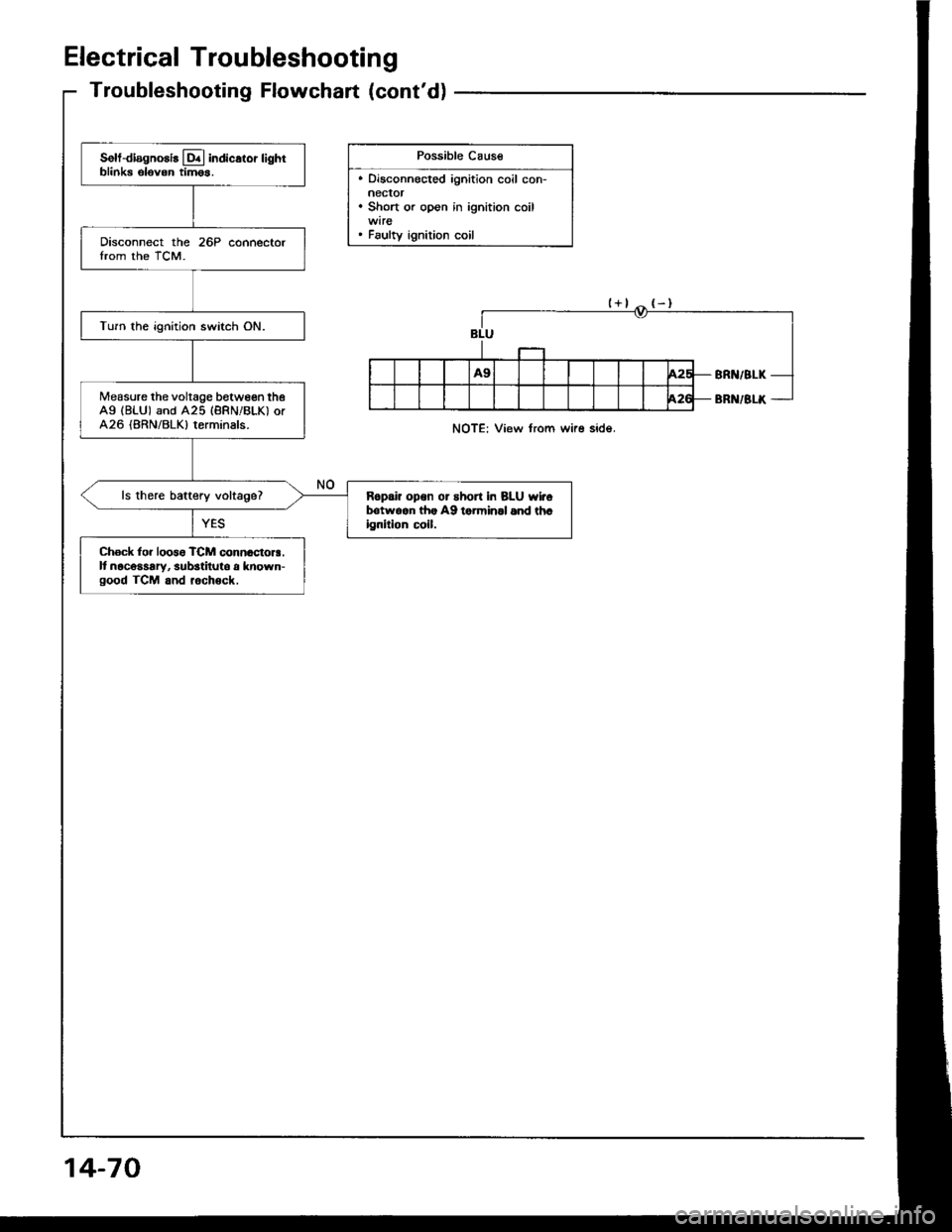
Possible Cause
. Disconnected ignition coil con-neclor. Short or open in ignition coil
. Faulty ignition coil
Solt-diagnosis lq.l indicstor lightblinks elovon tim6s.
Disconnect the 26P connectorIrom the TCM.
Turn the ignition switch ON.
Measure the voltage between theAg (BLU) and A25 (BRNiBLK) orA26 (BRN/BLK) terminals.
ls there baftery voltage?R6pai? opon or short in BLU wirolrotwqan lh. A9 torminll 6nd th.ignilion c!il.
Ch6ck lor loos6 TCM connactora.It nacosaary, substituto a known-good TCM and rochock.
NOTE: View from wire side.
14-70
Page 474 of 1413
Lock-up Control Solenoid Valve A/B
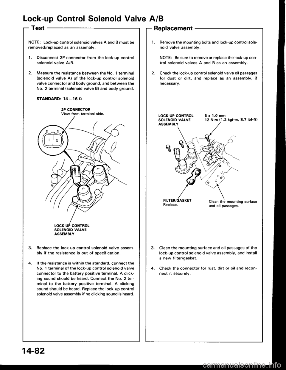
NOTE: Lock-uD control solenoid valves A and B must be
removed/replaced as an assemblv.
l. Disconnect 2P connector trom the lock-uo control
solenoid valve A/8.
2. Measure the resistance between the No. 1 terminal(solenoid valve A) ot the lock-up cont.ol solenoid
valve connector and body ground, and between the
No. 2 terminal (solenoid valve B) and body ground.
STANDARD: 14- 16 O
2P CONI{ECTORView trom terminal side.
SoLENOTO VAI-VEASSEMBLY
Reolace the lock-uo control solenoid valve assem-
bly if the resistance is out of specitication.
lf the .esistance is within the standard, connect the
No. 1 terminal ot the lock-uo control solenoid valve
connector to the battery positive terminal. A click-
ing sound should be heard. Connect the No. 2 ter-
minal to the battery positive terminsl. A clicking
sound should be heard. Replace the lock-up control
solenoid valve assembly if no clicking sound is heard.
?
4.
Replacement
Remove the mounting bolts and lock-up control sole-
noid valve assembly.
NOTE: Be sure to remove or replace the lock-up con-
trol solenoid valves A and B as an assembly.
Check the lock-up control solenoid valve oil passages
tor dust or dirt. and replace as an assembly, if
neceSsary.
6 x 1.0 mm12 N.m (1.2 kgf.m,8.7 lbf'ft)
Clean the mounting sudaceand oil passages.
Clean the mounting surtace and oil passages of the
lock-up control solenoid valve assembly. and install
a new filter/gasket.
Check the connector for rust, dirt or oil and recon-
nect rt securely.
14-82
Page 475 of 1413
Shift Control Solenoid ValveA/B
Test
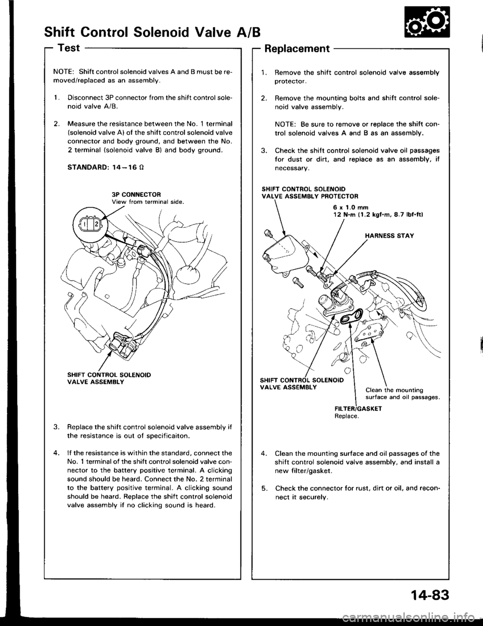
NOTE: Shift controlsolenoid valves A and B must be re-
moved/replaced as an assembly.
1.Disconnect 3P connector from the shitt control sole-
noid valve A/8.
Measure the resistance between the No. 1 terminal(solenoid valve A) of the shift control solenoid valve
connecto. and body ground, and between the No.
2 terminal (solenoid valve B) and body ground.
STANDARD: 14- 16 O
SHIFT CONTROL SOLENOIOVALVE ASSEMBLY
Replace the shift control solenoid valve assembly if
the resistance is out oI sDecificaiton.
lf the resistance is within the standard, connect the
No. 1 terminalof the shift controlsolenoid valve con-
nector to the battery positive terminal. A clicking
sound should be heard. Connect the No. 2 terminal
to the battery positive terminal. A clicking sound
should be heard. Replace the shift control solenoid
valve assembly if no clicking sound is heard.
3.
1.Remove the shift control solenoid vaive assembly
protector.
Remove the mounting bolts and shift control sole-
noid valve assembly.
NOTE: Be sure to remove or replace the shitt con-
trol solenoid valves A and B as an assembly.
Check the shitt control solenoid valve oil passages
for dust or dirt, and replace as an assembly, it
necessary.
Clean the mounting surface and oil passages of the
shitt control solenoid valve assembly, and install a
new filter/gasket.
Check the connector for rust, dirt or oil, and recon-
nect it securely.
6 x 1.0 mm12 N'm (1.2 kgl.m,4.7 lbl.ftl
VALVE ASS€MBLYClean the mountingsurface and oil passages.
Replace.
14-83
Page 479 of 1413
PROBABLE CAUSE
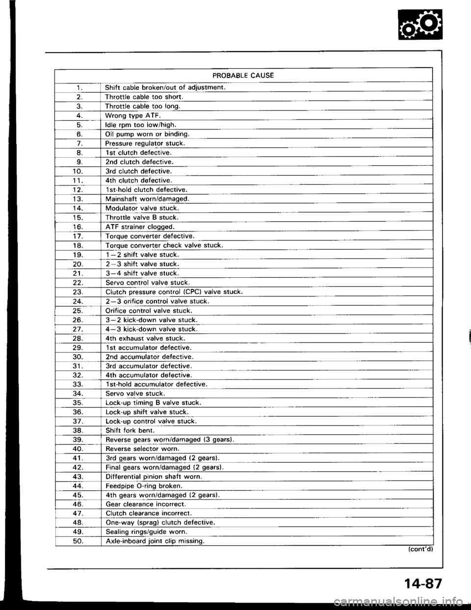
1Shitt cable broken/out of adiustment.
Throttle cable too short.
Throttle cable too long.
Wrong type ATF.
ldle rpm too low/high.
o.Oil pump worn or binding.
7.Pressure regulator stuck.
8.l st clutch detective.
9.2nd clutch detective.
10.3rd clutch defective.
114th clutch defective.
12.1 st'hold clutch defective.
13.Mainshatt worn/damaged.
14.Modulator valve stuck.
Throttle valve B stuck.
lo.ATF strainer clogged.
Toroue converter def ective.
18.Torque converter check valve stuck.'I 9.1-2 shift valve stuck.
2-3 shift valve stuck.
213-4 shift valve stuck.
Servo control valve stuck.
23.Clutch Dressure control (CPC) valve stuck.
2-3 orifice control valve stuck.
Orifice control valve stuck.
26.3-2 kick-down valve stuck.
27.4-3 kick-down valve stuck.
24.4th exhaust valve stuck.
29.1st accumulator detective.
30.2nd accumulator detective.
313rd accumulator defective.
4th accumulator defective.
1 st-hold accumulator defective.
Servo valve stuck.
35.Lock-up timing B valve stuck.
36.Lock-up shift valve stuck.
37.Lock-uo control valve stuck.
38.Shift fork benr.
39.Reverse gears worn/damaged (3 gears).
40.Reverse selectot worn.
413rd gears worn/damaged (2 gears).
Final qears worn/damaged (2 gearsl.
43.Differential Dinion shatt worn.
44.Feedpipe O-ring broken.
45.4th qears worn/damaged (2 gearsl
Gear clearance incorrect.
47.Clutch clearance incorrect.
48.One-way (sprag) clutch defective.
49.Sealinq rings/quide worn.
50.Axle-inboard joint clip missing.
Page 480 of 1413
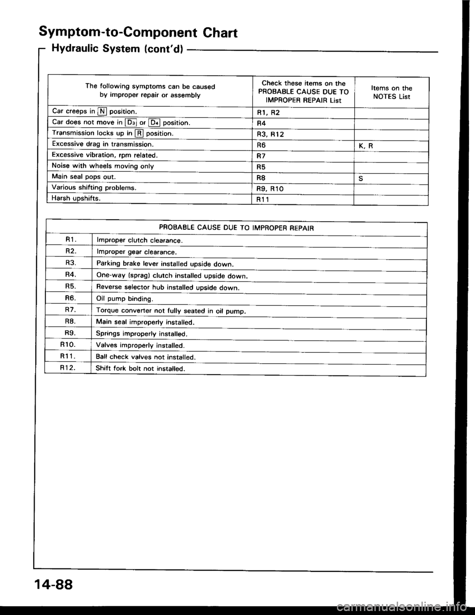
Symptom-to-Component Ghart
Hydraulic System (cont'd)
The following symptoms can be caused
by improper repair or assemblv
Check these items on the
PROBABLE CAUSE DUE TO
IMPROPER REPAIR List
Items on the
NOTES List
Car creeps in E position.R1, R2
Car does not move in @ or @ position.R4
Transmission locks up in @ position.R3, Rl2
Excessive drag in transmission.R6K.R
Excessive vibration, rom related.R7
Noise with wheels moving onlyR5
Main seal pops out.R8
Various shifting problems.R9, R1O
Harsh upshifts.R11
PROBABLE CAUSE DUE TO IMPROPER REPAIR
R1lmproper clutch cleatance.
R2.lmDroDer qear clearance.
Parking brake lever installed upside down.
One-way (spragl clutch installed upside down,
Reverse selector hub installed upside down.
Oil oumo bindind
Torque converter not fully seated in oil pump.
Main seal improperly installed.
Springs improperly installed,
Valves improperly installed.
Ball check valves not installed.
Shitt fork bolt not installed.
R3.
R4.
R5.
R6.
R7.
R8.
R9.
R10.
R11
R12.
14-88
Page 481 of 1413
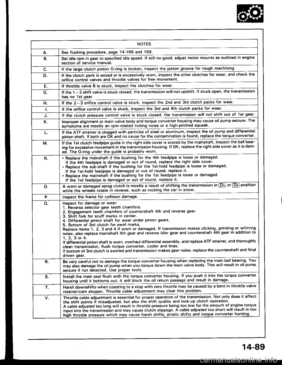
NOTES
A.See flushing procedure, page l4-168 and 169.
B.Set idle rpm in gear to specitied idle speed. lf still no good, adiust motor mounts as outlined in engine
section of service manual.
lf the large clutch piston O-ring is broken, inspect the piston groove for rough machining.
lf the clutch pack is seized or is excessively worn, inspect the other clutches Jor wear, and check the
orifice control valves and throttle valves for free movement.
E.It throttle valve B is stuck, inspect the clutches for wear.
lf the 1-2 shift valve is stuck closed, the transmission will not upshift. lI stuck open, the transmission
has no lst gear.
H.lf the 2-3 orifice control valve is stuck, inspect the 2nd and 3rd clutch packs for wear.
ll the orifice cont.ol valve is stuck, inspect the 3rd and 4th clutch packs for wear.
lf the clutch Dressure control valve is stuck closed, the transmission will not shilt out of 1st gear.
K.improper alignment or main valve body and torque converter housing may cause oil pump seizure. The
symptoms ale mostly an rpm-related ticking noise or a high-pitched squeak.
L.ll the ATF strainer is ctogged with panicles of steel or aluminum, inspect the oil pump and ditferential
pinion shaft. lt both are OK and no cause lor the contamination is found, replace the torque converter.
M.lf the 1st clutch feedpipe guide in the right side cover is scored by the mainshaft, inspect the ball bear-
ing for excessive movement in the transmission housing. lf OK. replace the right side cover as it is dent-
ed. The O-ring under the guide is probably worn.
N.ReDlace the mainshstt if the bushing for the 4th feedpipe is loose or damaged.
It the 4th feedpipe is damaged or out ot tound, replace the right side cover'
Replace the subjshaft it thtbushing for the 1st-hold Jeedpipe is loose or damaged.
lf the 1st-hold feedpipe is damaged or out of round, replace it.
Replace the mainshaft if the bushing lor the 1st feedpipe is loose or damaged.
lf the lst feedpipe is damaged or out ot round, replace it.
o.A *o- r, da."s"d "p-g clutch is mostly a result of shifting the transmission in El or Lq! position
while the wheels rotate in reverse, such as rocking the car in snow.
P.InsDect the frame for collision damage.
o.Inspect for damage or wear:
1. Reverse selector gear teeth chamfers.
2. Engagement teeth chamters of countershaft 4th and reverse gear.
3. Shift fork for scutt marks in center.
4. Differential Dinion shaJt for wear under pinion gears.
5. Bottom of 3rd clutch for switl marks.
Replace items 1 , 2, 3 and 4 it worn or damaged. lf transmission makes clicking, grinding or.whirring
noise, atso replace mainshaft 4th gear and reverse idler gear and countershaft 4th gear in addition to
1,2,3ot4.lf ditiersntial Dinion shaft is worn, overhaul differential assembly, and replace ATF strainel, and thoroughly
clean transmission, tlush torque convertet, cooler and lines.
lf bottom of 3rd clutch is swirled and transmission makes gear noise, replace the countershaft and tinal
driven gear.
R.Be wry careful not to dsmage the torque converter housing when replacing the main ballbearing. You
may al;o damage the oil pump when you torque down the main valve body. This will result in oil pump
seizure it not detected. Use proper tools.
qInstall the main seal tlush with the torque converter housing, lf you push it into the torque converter
housing until it bottoms out. it will block the oil return passage and result in damage.
T,Harsh do\/vnshiJt"\./l,'hen coasting to a stop with zero th.ottle may be caused by a bent-in throttle valve
retainer/cam stopper. Throttle cable adjustment may clear this problem.
ifuitle cable adjustment is essential for proper operation of the transmission. Not only does it affect
the shift points if misad,usted, but also the shift quality and lock-up clutch operation'
A cable adjusted too long will result in throttle pressure being too low for the amount of engine torque
input into ihe trsnsmission and may cause clutch slippage. A cable adjusted too short will result in too
hi;h throttle pressure which may cause harsh shitts, erratic shrfts and torque con
14-89
Page 484 of 1413
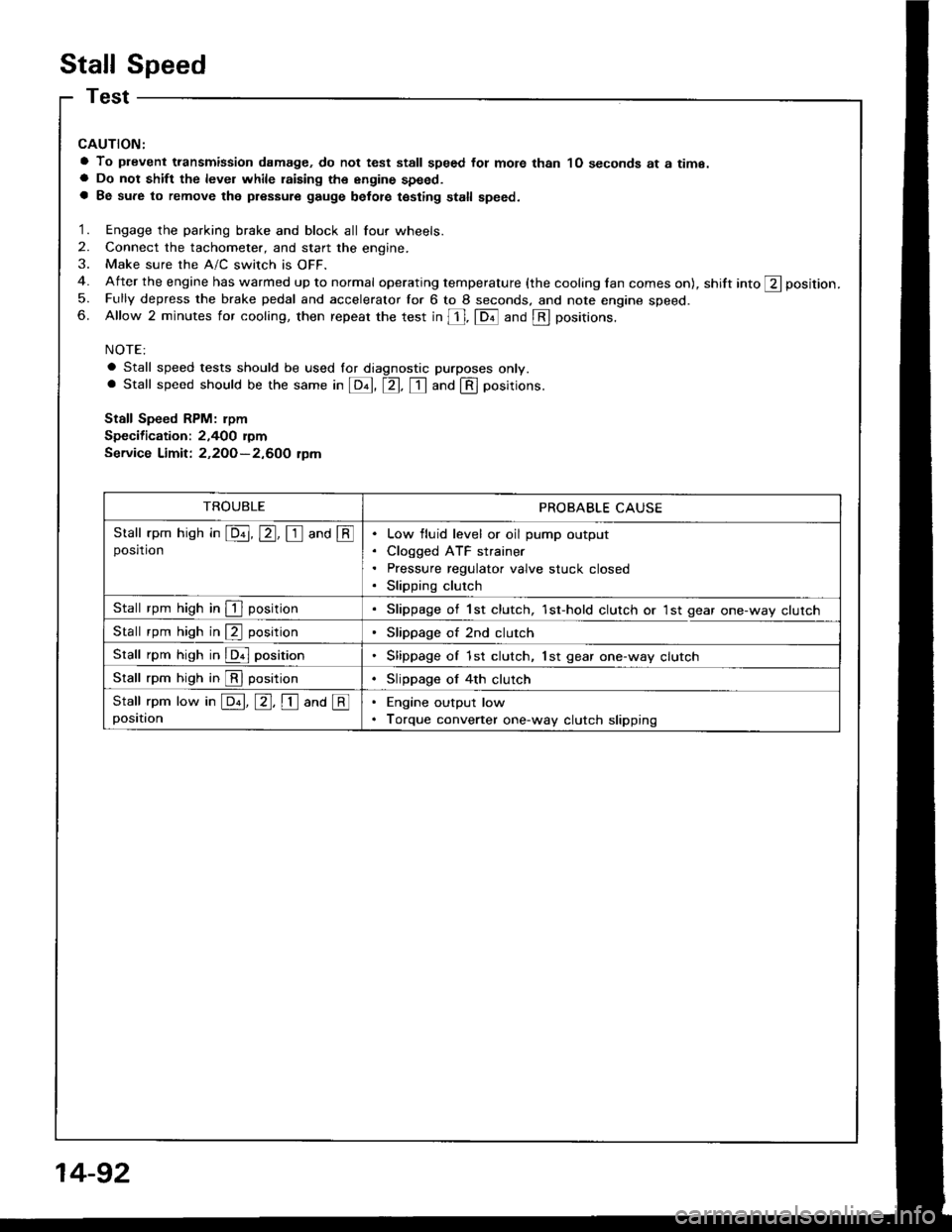
Stall Speed
CAUTION:
a To plevent transmission damage, do not test stall speed fot mote than 1O seconds at a time.a Do not shift the level while raising th€ engine speed.a Be sure to remove the pressure gauge belot€ testing stall speed.
1. Engage the parking brake and block all four wheels.
2. Connect the tachometer, and start the engine.
3. Make sure the A/C switch is OFF.
4. After the engine has warmed up to normal operating temperature (the cooling lan comes on), shift into ft position.
5. Fully depress the brake pedal and accelerator for 6 to 8 seconds. and note engine speed.6. Allow 2 minutes for cooling, then repeat the test in [, fDil and @ positions.
NOTE:
a Stall speed tests should be used lor diagnostic purposes only.. Stall speed should be the same in E, tr. tr and @ positions.
Stall Speed RPM: rpm
Specification: 2,400 rymService Limit: 2,2OO-2,600 tpm
TROUBLEPROBABLE CAUSE
Stall rpm hish in E, E, I and @posrtronLow fluid level or oil pump output
Cloqged ATF strainer
Pressure regulator valve stuck closed
Slipping clutch
Stall rpm high in I positionSlippage of 1st clutch, 1st-hold clutch or 1st gear one-way clutch
Stall rpm high in @ positionSlippage of 2nd clutch
Stall rpm high in @ positionSlippage of 1st clutch, lst gear one-way clutch
Stall rpm high in @ positionSlippage of 4th clutch
Stall rpm low in E, E, I ana @positionEngine output low
Torque converter one-way clutch slipping
14-92
Page 486 of 1413
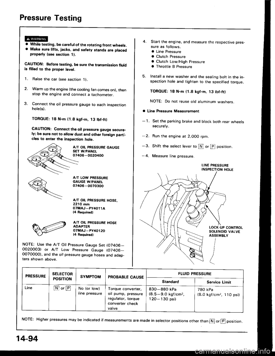
Pressure Testing
a While testing, be caretul of the rotating flont wheels.a Make aura litts, jacks, and sat€ty stands alo placedplop6rly {see section 1}.
CAUTION: Betore t€sting, be sure the transmission fluidis tilled to rh6 ploper l€vet.
1. Raise the car (see section i),
2. Warm up the engine {the cooling fan comes onl, thenstop the engine and connect a tachometer.
3. Connect the oil pressure gauge to each inspectionholels).
TOROUE: 18 N.m (1.8 kgf.m, 13 tbf.fr)
CAUTION: Connect ths oil prsssure gauge s€cur€_ly; be sule not to allow dust and other foleign pani_cl6s to 6nt€1 th€ inspection holo.
A/T OIL PRESSURE GAUGESET WPANEL07406-002oi+oo
A/T LOW PRESSUREGAUGE W/PANEL07/rO6-0O70300
A/T OIL PRESSURE HOSE,22'10 mmOTMAJ_PY4OI TA{4 Roquirod)
A/T OIL PRESSUBE HOSEADAPTEROTMAJ - PY/+O12014 Roqui.odl
NOTE: Use the A/T Oil Pressure Gauge Set (07406_O02OOO3) or A/T Low Pressure Gauge (07406-OOTO0OO). and the oil pressure gauge hoses and adap_ters shown above.
14-94
4. Start the engine, and measure the respective pres-
sure as follows.
a Line Pressure
a Clutch Pfessure
a Clutch Low/High Pressure
a Throttle B Pressure
5. Install a new washer and the sealing bolt in the in-spection hole and tighten to the specified torque.
TOROUE: 18 N'm {1.8 kgf.m, 13 tbf.ft)
NOTE: Do not reuse old aluminum washers.
a Line Pressure M€asurement
- 1 . Set the parking brake and block both rear wheelssecurely.
-2. Run the engine at 2,OOO rpm
-3. Shift the selecr lever to S or @ position.
-4. Measure line pressure.
LINE PRESSUREINSPECTION HOLE
NoTE: Higher pressures may be indicated it measurements are made in selector positions other than @ or @ position.
PRESSURESELECTOR
POStTTONSYMPTOMPROBABLE CAUSEFLUID PRESSURE
StandardService Limit
LineNo'ENo (or low)
lrne pressureTorque converter,
orl pump, pressure
regulator, to.que
convener check
valve
83O-88O kPa(8.5-9.O kgf/cm,,
120- I 30 psi)
78O kPa
{8.0 kgl/cm,, 1lO psi}
Page 488 of 1413
Pressure Testing
(cont'dl
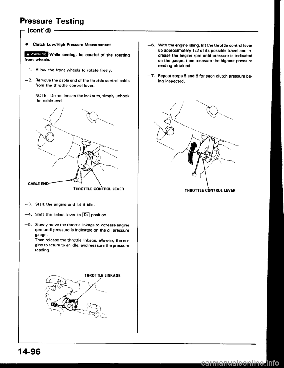
a Clutch Low/High P.essure Measuroment
@[ wtite resring. b€ calefut ot tha loraringflont wh66ls.
- 1. Allow the front wheels to rotate freely.
-2. Remove the cable end of the throttle control cable
from the throttle control lever.
NOTE: Do not loosen the locknuts. simplv unhookthe cable end.
CAALE END
-3. Start the engine and let it idle.
-4. Shitt the select leve. to E position.
-5. Slowly move the throttle linkage to increase enginerpm until pressure is indicaied on the oil oressuregauge.
Then release the throttle linkage, allowing the en-grne to return to an idle, and measure the Dressureresding.
14-96
-6. With the engine idling, lift the throttle control lever
up approximately 1/2 of its possible travel and in-
crease the engine rpm until pressure is indicated
on the gauge, then measure the highest pressure
reading obtained.
- 7. Repeat steps 5 and 6 for each clutch pressure be-
ing inspected.
Page 490 of 1413
Pressure Testing
(cont'dl
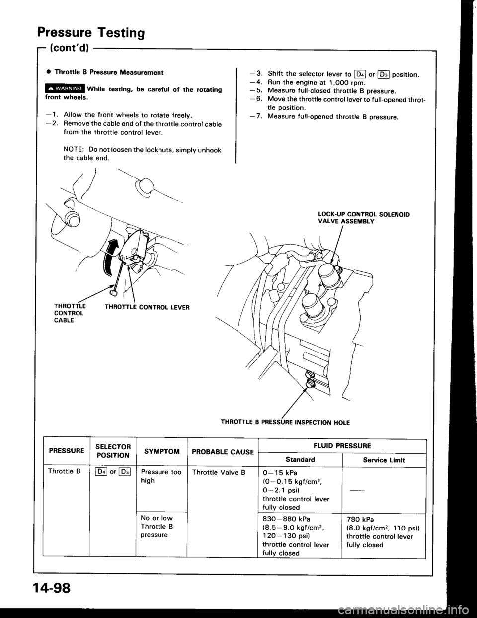
a Throttle B Ptsssure Measuremcnt
@@ wrril" resring, be caretut ot rhe rotaringfront wheels.
1. Allow the front wheels to rotate treelv.-2. Remove the cable end of the throttle controlcablefrom the throttle control lever.
NOTE: Do not loosen the locknuts, simply unhookthe cable end.
3. Shift the selector lever to @ or @ position.-4. Run the engine at 1,OOO rpm-5. Measure full-closed throttle B pressure.-6. Move the throttle control lever to full-opened throt-tle position.-7. Measure full-opened throttle B pressure.
PRESSURESELECTOR
POSTTTONSYMPTOMPROBABLE CAUSEFLUID PRESSURE
StandardS€rvica Limit
Throttle Bloil or lDllPressure too
high
Thfottle Valve BO-15 kPa
{O-O.1 5 kgf/cm,,
0-2.1 psi)
throttle control lever
fully closed
No or low
Throttle B
pressure
83o 88O kPa(8.5-9.O kgf/cmz,
120 130 psi)
thfottle control levet
fully closed
78O kPa(8.O kgl/cm,, l lO psi)
throttle control lever
tully closed
14-98