Oil HONDA INTEGRA 1994 4.G Workshop Manual
[x] Cancel search | Manufacturer: HONDA, Model Year: 1994, Model line: INTEGRA, Model: HONDA INTEGRA 1994 4.GPages: 1413, PDF Size: 37.94 MB
Page 351 of 1413
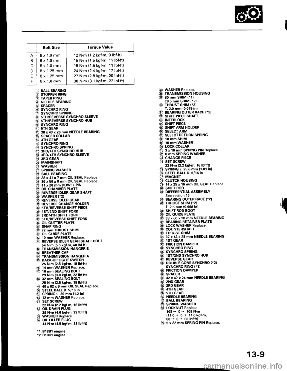
12 N.m (1.2 kgim,9 lbnft)
15 N.m (1.5 kgnm, 11 lbf.ft)
15 N.m (1.5 kgf.m, 11 lbf.ft)
24 N.m (2.4 kgf.m, 17 lbf'ft)
27 N.m (2.8 kgnm,20 lbnft)
30 N.m (3.1 kgf.m, 22 lbf'ft)
Bolt Size
,l
{
@@69
@
@@@@@@@@6Dq0
o€xv0@
@0!@@@@al
61@
B
c
D
E
F
6x1.0mm
6x1.0mm
I x 1.0 mm
8 x 1.25 mm
8 x 1.25 mm
8 x 1.0 mm
i) BALL BEARINGe sroPPER R|NG9 TAPER RINGA NEEDLE EEARINGO SPACER.d SYNCHRO RINGt sYNcHRo SPR|NG!) 5TH/REVEFSE sYNcHRo SLEEVEO 5TH/REVERSE SYNCHRO HUB[0 sYrucxao nlrucii i) 5TH GEARO 38 x 43 x 26 mm NEEDLE BEARINGt3 SPACEE COLLARO 4TH GEAR.iB SYNCHRO FING.Ii9 SYNCHRO SPRING{, 3RD/,ITH SYNCHRO HUB
@ 3RD/4TH SYNCHBO SLEEVEt9 3RD GEARO MAINSHAFTO wasHER@) SPRING WASHER40 BALL BEARINGO 28 x 41 x ? mm OIL SEAL Replace.ad 35 x 56 x 8 mm OIL SEAL Replace.a0 14 x 20 mm OOWEL PIN@ OIL CHAMBER PLATE'A BEVERSE IDLEN GEAR SHAFT@ wasHER t-2).A REVERSE IDLER GEAFO REVERSE CHANGE HOLDER3A sTH/REVERSE SHIFT PIECEO 1ST/2ND SHIFT FORK04 3RD/.TH sHlFr FoRK@ 5TH/REVERSE SHIFT FORKO9' OIL GUTTER PLATE6' SNAP RING@ 72 mm THRUST SHIM) OIL GUIOE PLATEi!0 10 mm WASHER Replace..4i] REVERSE IDLER GEAR SHAFT BOLT54 N.m {5.5 kgt m, 40lblftl) TRANSMISSION HANGER B(3 BREATHER CAP@ TRANSMISSION HANGER A63 BACK.UP LIGHT SWITCH25 N.m (2.5 ksf.m, 18lbfftl@r 14 mrn waSHER Replace.67 16 mm SEALING BOLT29 N.m (3.0 kgl.m, 22 lbf ft)@ 32 mm SEALING BOLT25 N.m (2.5 kgf.m. 18lbt'ft|@ 40 x 62 x 9 mm OIL SEAL Replace.D STEEL BALL D. 5/16 inGl SPRING L. 30 mm {1.2 in}
@ 12 mm WASHER Replace.63) SET SCREW22 N.m 12.2 kgl.m, 16 lbt'ft,@ OIL ORAIN PLUG39 N.m {4.0 kgt.m, 29 lbf'ftl€9 WASHER Replace.@ oIL FILLER PLUG4,1N.m 14.5 kgJ m, 33 lblftl
*1:81881 engine*2:B18Cl engine
WASHER Beplace.TRANSMISSION HOUSING80 mm SHIM (*1)79.5 mm SHIM {*21THRUST SHIM {*2IT. 2.0 mm (0.079 in)BEARING OUTER RACE {*2}SHIFT PIECE SHAFTINTERLOCKSHIFT PIECESHIFT ARM HOLDERSELECT ARMSELECT RETURN SPRING10 mm SHIM10 mm WASHERLOCK COLLAR3 x 16 mm SPRING PIN Replace.8 mm SPRING WASHERCHANGE PIECESET SCREW22 N.m {2.2 kgf.m, 16 lbf.ft}SPRING L.25.6 mm {1.01 inlSTEEL BALL D. 5/16 inMAGNETCLUTCH HOUSING14 x 25 x 16 mm OIL SEAL Replace.SHIFT RODDIFFERENTIAL ASSEMBLYSee section 15BEARING OUTER RACE I*2ITHRUST SHIM I*2)T. 2.5 mm (0.098 in,SHIFT ROD BOOTOIL GUID€ PLATE33 x 60 x 20 mm NEEDLE BEARINGBEARING RETAINER PLATELOCK WASHER Replace.COUNTERSHAFTTHRUST SHIM37 x 42 x 25 mm NEEDLE BEARINGlST GEARFRICTION DAMPERSYNCHRO RINGSYNCHRO SPRINGlST/2ND SYNCHRO HUBREVERSE GEARDOUBLE CONE SYNCHRO I*2ISYNCHRO BING I*1)FRICTION DAMPERSPACER42 x 6? x 24 mm NEEDLE BEARING2ND GEAR3RD GEAR4TH GEAS5TH GEARNEEDLE BEARINGBALL BEARINGSPRING WASHERLOCKNUT Replace.108 - 0- 108 N.m(11.0 - 0* 11.0 kgt m,80- 0- 80lbf.ft)5 x 22 mm SPRING PIN Replace.00
13-9
Page 353 of 1413
Reverse Change Holder,
Reverse ldler Gear
Clearance Inspection
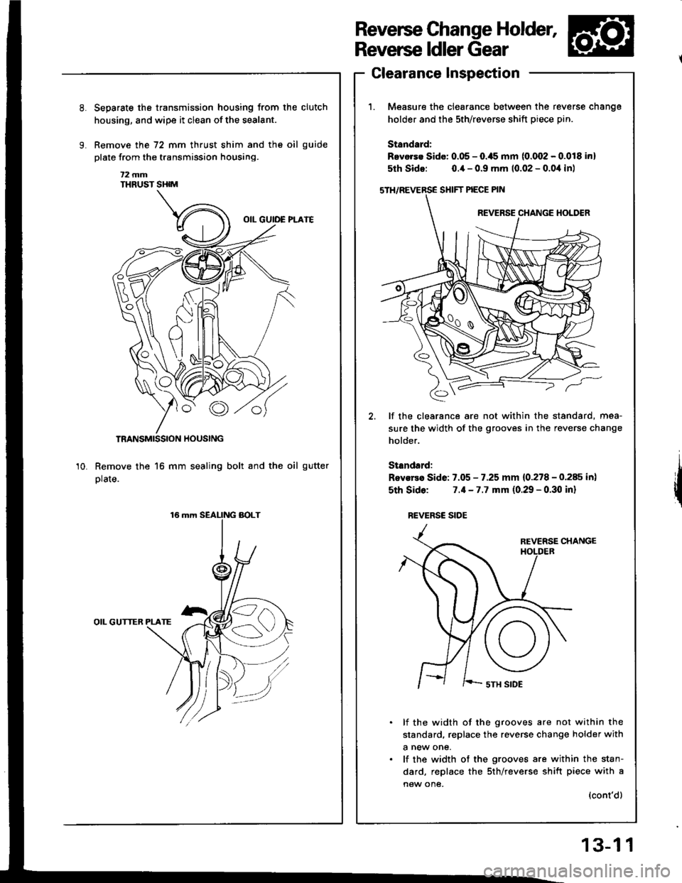
Measure the clearance between the re
holder and the sth/revsrse shift piece p
Standard:
Bevorse Sido: 0.05 - O.ils mm (0.002 - (
5th Sido: o.ia - 0.9 mm 10.02 - 0.0,1
SHIFT PIECE PIN
REVERSE CHANGE
€,
lf the clearance are not within the sti
sure the width of the grooves in the re
holder.
Standsrd:
Rovsrea Side: 7.05 - 7.25 mm {0.278 - (
sth Sido: 7.1-7.7 mm (0.29 - 0.30
REVERSC SIOE
REVERSE
I ' '-- sTH SIDE
lf the width of the grooves are n
standard, replace the reverse chan€
a new one.
lf the width of the grooves are wi
dard, replace the sth/reverse shift
new one,
Separste the transmission housing from the clutch
housing, and wipe it clean of the sealant.
Remove the 72 mm thrust shim and the oil guide
plate from the transmission housing.
t2 mmTHRUST SHIM
TRANSMISSION HOUSING
Remove the 16 mm sealing bolt and the oil gutter
plate.
OIL GUTTER PLATE
10.
reverse cnange
ptn.
.0.018 inl
),1in)
standard, mea-
reverse change
0.285 in)
I inl
not within the
Inge holder with
within the stan-
rift piece with a
(cont'd)
13-1 1
Page 360 of 1413
Shift Rod
CHANGE PIECE
SPRINGL 25.6ll.0r in,
STEEL AALL(D.5/16
SPRING WASHER
Removal
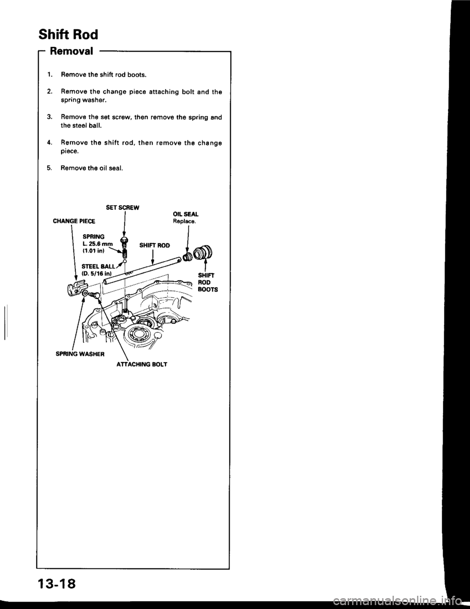
1. Remove the shift rod boots.
2. Romove the change piece sttaching bolt and the
spring washer.
3. Remove the set screw, then remove the spring and
the steol ball.
4. Remov€ tho shitt rod, then remove the chsngepiece.
5. Remove th€ oilseal.
OIL SEALRoploc€.
*q
ACHING BOLT
SET SCBEW
13-18
Page 368 of 1413
Mainshaft Assembly
Inspection
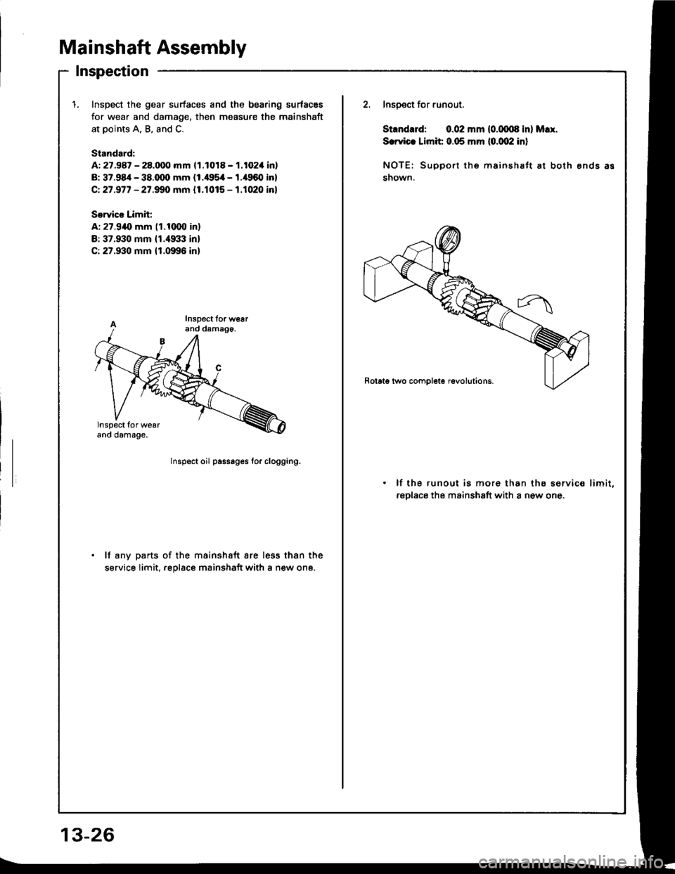
1.Inspect the gear surfaces and the bearing surfacss
for wear and damage, then measure the mainshaft
at points A, B. and C.
Standord:
A: 27.987 - 28.000 mm 11.1018 - 1.102'l inl
B: 37.98/r - 38.q)0 mm {1.il95il - l.il960 in}
Ct 27.977 - 27.99O mm {1.1015 - 1.1020 in}
S€rvico Limit;
A: 27.9{, mm (1.1(XXl in}
B:37.930 mm 11.4933 inl
C: 27.930 mm {1.0996 in}
2. Inspect for runout.
Stlnd.rd: 0.02 mm (0.(xxl8 inl M!I.
S.rvic. Limit 0.05 mm (o.qP inl
NOTE: SuDport the mainsh€ft at both ends as
shown.
Inspect oil passages tor clogging.
lf the runout is mor6 than ths service limit,
rsplace the mainshaft with a n6w one.
lf any parts of the mainshaft are less thsn the
service limit. .eolace mainshaft with a new one.
13-26
Page 373 of 1413
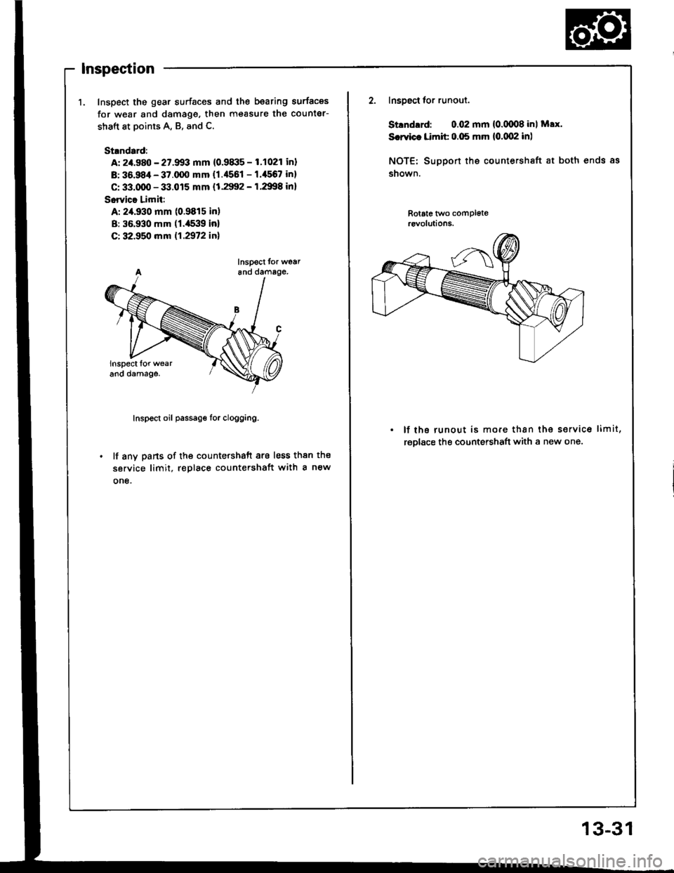
Inspection
1. Inspect the gear surfaces and the bearing surfaces
for w€ar and damage, then measure the counter-
shaft at points A, B, and C.
St.ndard:
A: 2/t.980 - 27.9!13 mm (0.91|:15 - 1.1021 inl
B: 36.984 - 37.q)O mm {1.4551 - 1.'156? in}
C: 33.qD - 33.015 mm (1.2992 - 1.2998 inl
Sorvica Limit:
A: 2,a.930 mm (0.9815 in)
B: 35.930 mm (1.a539 inl
C: 32.950 mm 11.2972 inl
Inspect tor wear6nd damage.
Inspect oil passage lor clogging.
lf any parts of the countershaft are less than the
service limit, replace count€rshaft with a new
one.
Inspgct tor runout.
Stlndrrd: 0.02 mm {0.(xn8 inl Max.
Srrvic. Limit 0.05 mm {0.(x)2 in)
NOTE: Suppon the countershaft at both ends as
snown.
Rotate tl/vo compl6t€rcvolutions.
. lf the runout is more than the servic6 limit,
rgDlace the countershaft with a new one.
13-31
Page 377 of 1413
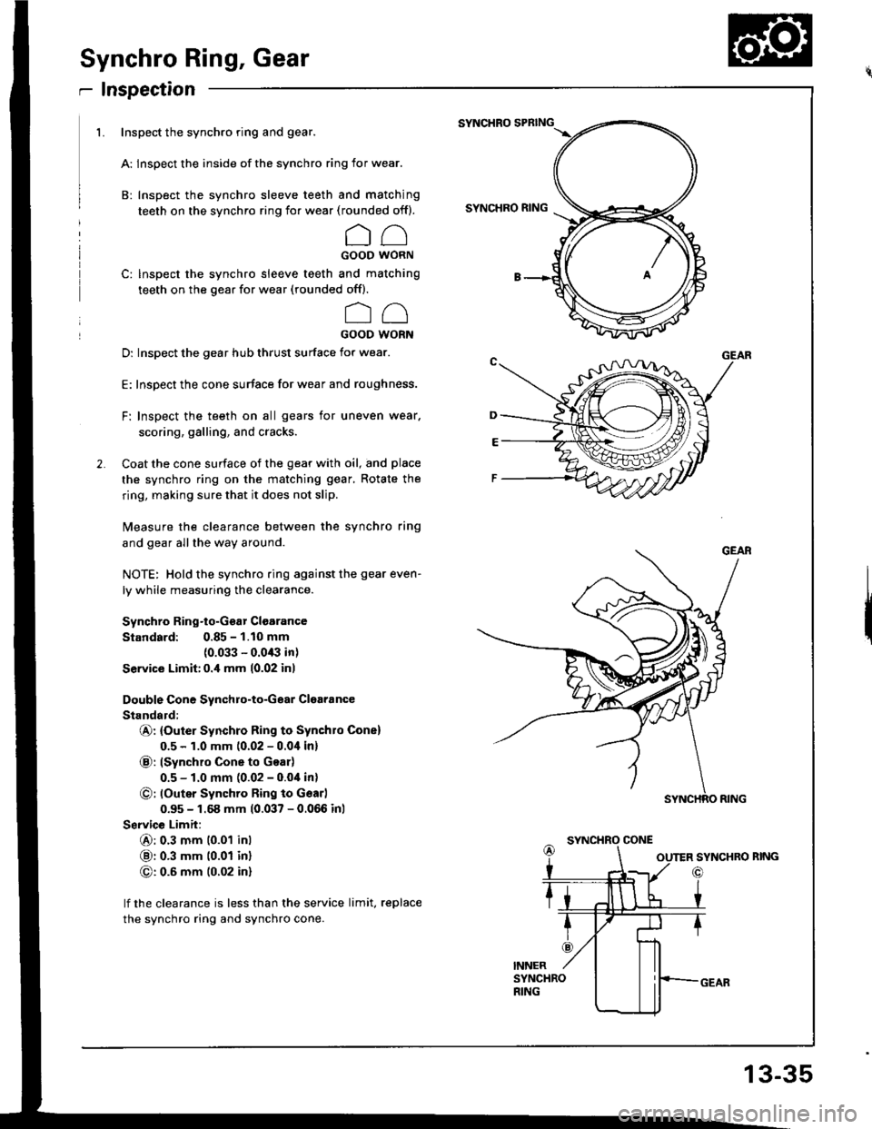
Synchro Ring, Gear
r Inspection
1. Inspect the synchro ring and gear.
A: lnspect the inside of the synchro ring for wear.
B: Inspect the synchro sleeve teeth and matching
teeth on the synchro ring for wear (rounded off).
CCGOOD WORN
C: Inspect the synchro sleeve teeth and matching
teeth on the gear for wear (rounded offl.
oo
GOOD WORN
D: Inspect the gear hub thrust surface for wear.
E: Inspect the cone surface for wear and roughness.
F: Inspect the teeth on all gears for uneven wear.
scoring, galling, and cracks.
Coat the cone surface of the gear with oil, and place
the synchro ring on the matching gear, Rotate the
ring, making sure that it does not slip.
Measure the clearance between the synchro ring
and gear allthe way around.
NOTE: Hold the synchro ring against the gear even-
ly while measuring the clearance.
Synchro Ring-to-Ggar Clgarance
Standard: 0.85 - 1.10 mm(0.033 - 0.0/B in)
Service Limit:0.i1 mm 10.02 inl
Double Cone Synchro-to-Gear Cloaiance
Standald:
@: {Outer Synchro Ring to Synchro Cone)
0.5 - 1.0 mm 10.02 - 0.0i1in)
@: lSynchro Cone to Goar)
0.5 - 1.0 mm (0.02 - 0.04 in)
O: loutsr Synchro Ring to Gsarl
0.95 - 1.68 mm (0.037 - 0.066 inl
Service Limit:
6): 0.3 mm 10.01 inl
@: 0.3 mm t0.01 inl
G): 0.6 mm (0.02 in)
lf the clearance is less than the service limit, replace
the synchro ring and synchro cone.
SYNCHRO SPBING
SYNCHRO RING
SYNCHRO CONE
SYNCHRO RING
o
13-35
Page 378 of 1413
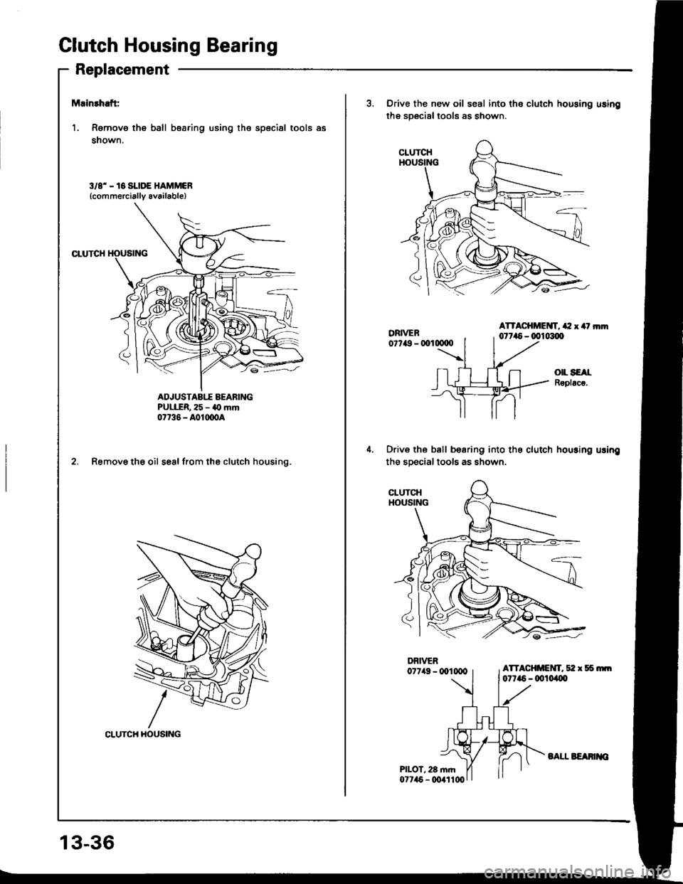
Clutch Housing Bearing
Replacement
Mainrhaft:
1. Remove the ball bearing using the special tools as
shown.
3/8' - 16 SI.IDE HAMMCR(commercially av6ilable)
CTUTCH
ADJUSTABIT AEARINGPULER, 25 - a0 mrn07736 - A01moA
2. Remove the oil seal from the clutch housing.
CLUTCH HOUSING
3. Drive the new oil seal into the clutch housing using
the specialtools as shown.
ATTACHMEIVT, a2 x 4t rnm0r7a5 - 0010300
()|L SEAIRoplacs.
Drive the ball bearing into the clutch housing usin!
the sDecial tools as shown.
13-36
BATI. BEAMIO
Page 379 of 1413
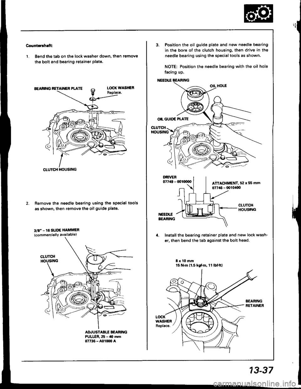
Countcr'h!ft:
'1. Bsnd the tab on the lock washer down, then remove
the bolt 8nd bearing retainer plate.
Remove th€ needle bearing using the specisl
as shown, then remove the oil guide pl8te.
3rE' - 16 SUI'€ HAiiMER
{commorcially availabls)
lools
AD.'USTABII BEARIITGPULIIR, 25 - ao mm07t36 - A0rm0 a
CLUTCH HOUSING
3. Position the oil guide plate and new needle bearing
in the bore of the clutch housing, then drive in the
needle bearing using the specialtools as shown.
NOTE: Position the needle bearing with the oil hole
facing up.
OIL GUIDC PLATE
CI-UTCHHOUSING
Install the bearing retainer plate and new lock wash-
er, then bend the tab againstthe bolt head.
8x 10 mm15 N.m ll.5 kd.m, 11 lbf.ttl
LOCKWASHEARepl6ce.
13-37
Page 380 of 1413
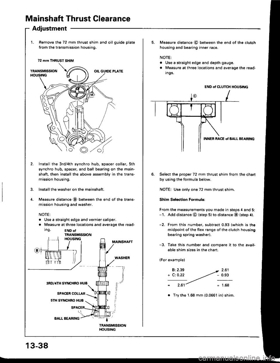
Mainshaft Thrust Glearance
1. Remove the 72 mm thrust shim and oil guide plate
from the transmission housing.
72 mm THRUST SHIM
TRANSMISSIONHOUSINGOIL GUIDE PLATE
Adjustment
\.u
o
Bo
lnstall the 3rd/4th synchro hub, spacer collar, sth
synchro hub, spacer, and ball bearing on the main-
shaft. then install the above assembly in the trans-
mission housing.
Installthe washer on the mainshaft.
Measure distance @ between the end of the trans-
mission housing and washer.
NOTE:
. Use a straight edge and vernief caliper.
. Measure at three locations and averaoe the read-
Ing.END olTRANSMISSIONHOUSINGMAINSHAFT
WASHER
fr
13-38
AALL AEARING
. Try the 1.68 mm (0.0661 in) shim.
5. Measure distance @ betlveen the end of the clutch
housing and bearing inner race.
NOTE:
. Use a straight edge and depth gauge.
a Measure at three locations and average the read-
Ings.
Select the prcpet 72 mm thrust shim from the chart
by using the formula below.
NOTE: Use only one 72 mm thrust shim.
Shim Sslsction Formula:
From the measurements you made in steps 4 and 5:-1. Add distance @ (step 5lto distance @ (step 4).
-2. From this number. subtract 0.93 (which is the
midpoint of the flex range of the clutch housing
bearing spring washerl.
-3. Take this number and compare it to the avaif
able shim sizes in the chart.
(For example)
B:2.39
+ C: O.22
2.61- 0.93
1.68
END of CLUTCH HOUSING
INNEB RACE ot BALL BEARltac
Page 381 of 1413
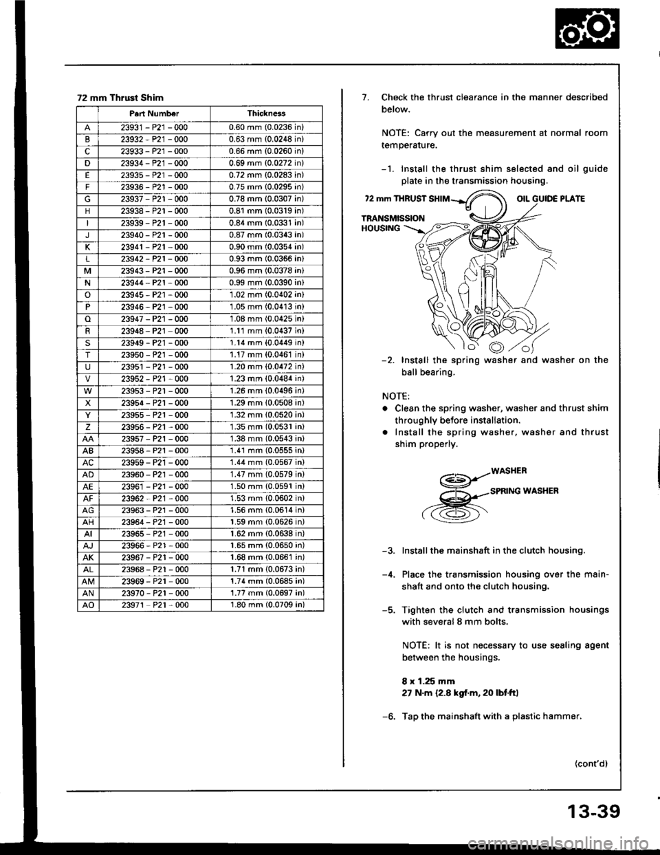
72 mm Thrust Shim
Part NumberThickness
23931 - P21 -0000.60 mm (0.0236 in)
23932-P21 -0000.63 mm (0.0248 in)
c23933 - P21 -0000.66 mm {0.0260 in}
D23934-P21 -0000.69 mm (0.0272 in)
23935 - P21 -0000.72 mm (0.0283 in)
F23936-P21 -0000.75 mm (0.0295 in)
23937-P21 -0000.78 mm (0.0307 in)
23938-P21 -0000.81 mm (0.0319 in)
23939-P21 -0000.84 mm (0.0331 in)
J23940-P2r-0000.87 mm (0.0343 in)
K23941 - P21 -0000.90 mm (0.0354 in)
L23912-P21-OOO0.93 mm (0.0366 in)
M23943-P21 -0000.96 mm (0.0378 in)
N23944-P21 -0000.99 mm (0.0390 in)
o23915 - P21 -0001.02 mm (0.0402 in)
P23946 - P21 ,0001.05 mm (0.04'13 in)
o23947 -P21 -0001.08 mm (0.0425 in)
23948 - P21 0001.11 mm {0.0437 in}
s23919-P21 -0001.14 mm (0.0449 inl
T23950-P21 -0001.17 mm (0.0461 in)
23951 - P21 -0001.20 mm {0.0472 in)
23952 - P21 0001.23 mm {0.0484 in)
23953-P21 -0001.26 mm (0.0496 in)
X23954-P2r-0001.29 mm 10.0508 in)
23955-P21 -0001.32 mm 10.0520 in)
z239s6-P21 ,0001.35 mm (0.0531 in)
23957-P21 -0001.38 mm (0.0543 inl
AB23958 - P21 -0001.41 mm (0.0555 in)
AC23959 - P21 -0001.44 mm (0.0567 in)
AD23960 - P21 -0001.47 mm (0.0579 in)
AE23961 -P21 -0001.50 mm {0.0591 in)
23962 P21 ,0001.53 mm {0.0602 in)
23963-P21 -0001.56 mm {0.0614 in}
AH23964 - P2'1 -0001.59 mm (0.0626 in)
AI23965 - P2'1 -0001.62 mm (0.0638 in)
23966-P21 -0001.65 mm (0.0650 in)
AK23967-P21 -0001.68 mm {0.0661 in)
23968 - P21 -0001.71 mm 10.0673 in)
23969 - P21 0001.74 mm (0.0685 in)
AN23970-P21 -000'1.77 mm (0.0697 in)
AO23971 P21 0001.80 mm (0.0709 in)
7. Check the thrust clearance in the manner described
below.
NOTE: Carry out the measurement at normal room
remperarure.
-1. Install the thrust shim selected and oil guide
plate in th€ transmission housing.
?2 mm THRUSTotLPLATE
TRANSMISSIONHOUSING
Install the spring
ball bearing.
washer and washer on the
NOTE:
. Clean the spring washer, washer and thrust shim
throughly before instaliation.
. Install the spring washer. washer and thrust
shim properly.
a-=s-.r*os".^
.,,-B*^INGWASHER
-4.
Installthe mainshaft in the clutch housing.
Place the transmission housing over the main-
shaft and onto the clutch housing.
Tighten the clutch and transmission housings
with severalS mm bolts.
NOTE: lt is not necessary to use sealing agent
between the housings.
8 x 1.25 mm
27 N.m {2.8 kgf.m, 20 lbf.ft}
Tap the mainshaft with a plastic hammer,
(cont'd)
13-39