body HONDA INTEGRA 1994 4.G Workshop Manual
[x] Cancel search | Manufacturer: HONDA, Model Year: 1994, Model line: INTEGRA, Model: HONDA INTEGRA 1994 4.GPages: 1413, PDF Size: 37.94 MB
Page 1052 of 1413
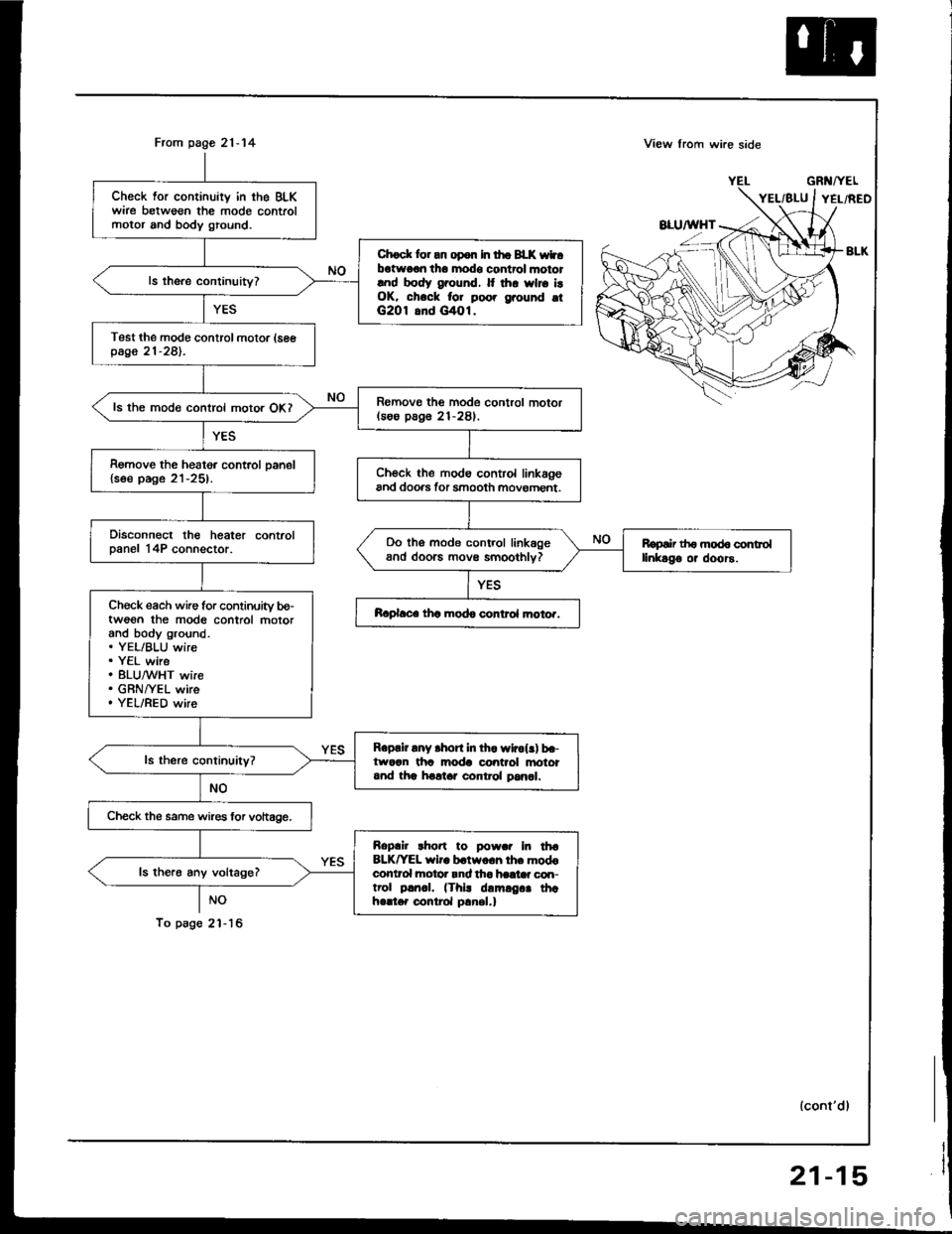
From page 21-14
NO
To psg6 2'l - 16
Check for continuity in the BLKwire betweon the mode controlmotor and body ground.
Chock lor an op6n In tho BLK wtbotwo€n tho modo control mototlnd body ground. It thr wlro i!OK, chock for poo. grouhd otG2O1 8nd G/tOl.
Test the modo control motor (seepage 21-281.
Romovo the mode control motor(soo pag6 21-281.ls the mode control motor OKI
Remove the heater control oanel{soe page 21-25).Ch€ck the modo control linkagoand doo.s tor smooth movoment.
Disconnect the heater controlDanel 14P connector.Do tho mode control linkageand doorc movs smoothlv?Ropair th6 mod6 controllinkago or doors.
Ch€ck each wire for continuity bo-twoon the mod6 control motorand body ground.. YEL/BLU wire. Y€L wire. 8LU,^/VHT wire. GRNI/EL wire. YEL/RED wire
Raplace thc modo control moto..
Roprir any .hort in th. wlrol!) b.-tworn tha moda control anototand tha holtar control pan6l.
Check the same wires lor vohage.
Roplir rho.t to powar In tha8LK^'EL wiro b.two.h lh. modoconlrol hotor rnd tha haat* con-trol p!rr.|. (Thi! damrg.. thahello. control p!nel.)
ls the.6 any voltage?
View lrom wi.e side
GRl{/YEL
lconl'dl
21-15
Page 1054 of 1413
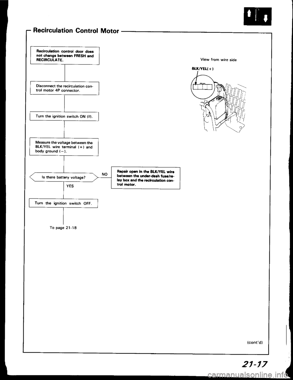
Recirculation Control Motor
ffi
Rocirculation control doo. dooanot chsng€ botwoon FRESH 6ndRECIRCULATE.
Disconnect the rgcirculation con-trol motor 4P connector.
Turn the ignilion switch ON l).
Measure the voltage between theBLK^/EL wire rerminal {+) andbody ground (- ).
Reprir op.n In th. BIK/YEL wir.botwoon thr und.r+rh fu!./r.-by box 6nd lha radrculdion co.r-trol motoi.
ls there battery voltage?
Turn the ignition switch OFF.
To page 21-18
{cont'd)
21-r 7
Page 1055 of 1413
Troubleshooting
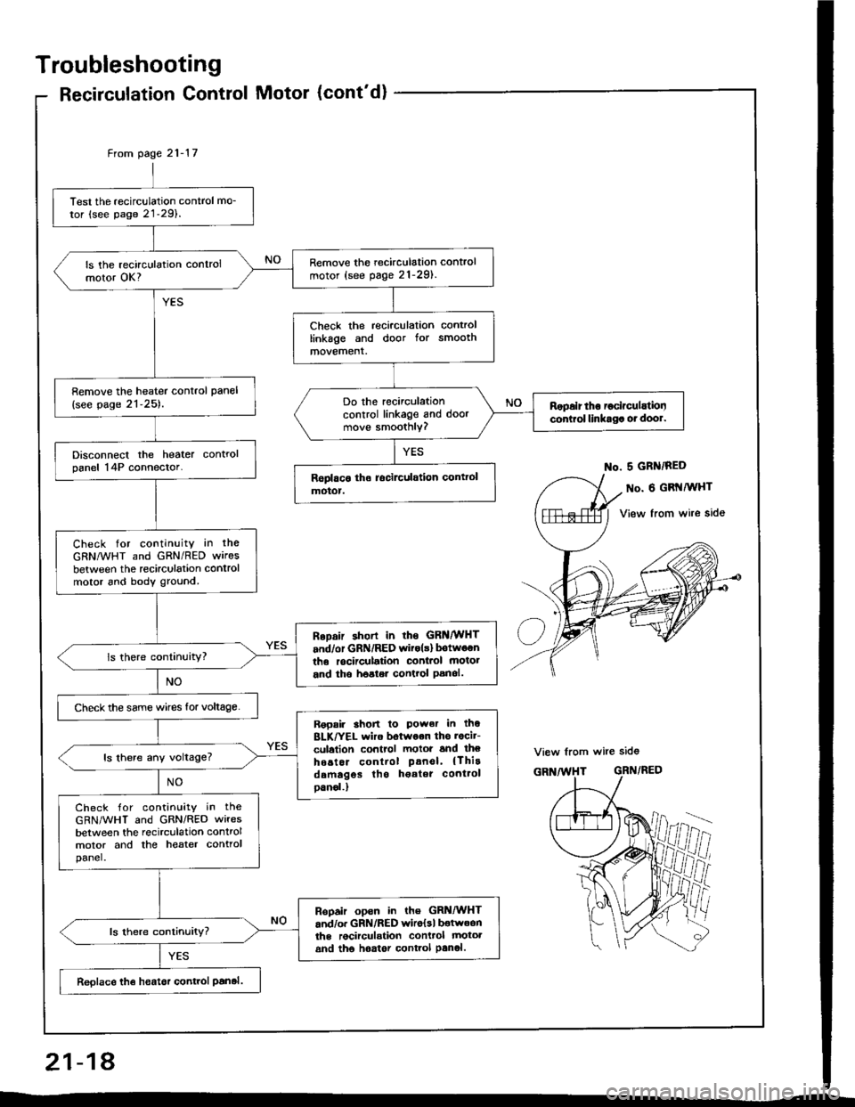
Recirculation Control Motor (cont'd)
Test the recirculation control mo_
tor (see page 21-29).
Remove the recirculation control
motor (see pag. 21-291.ls the recirculation controlmotor OK?
Check the recirculation controllinkage and door for smoothmovement.
Remove the heater control pan€l
{see page 21-25).Do the recirculationcontrol linkage and doormove smoothly?
Ropalr tho ioclrculatiooconirol linkaga ot dool.
Disconnect the heater controlpanel 14P connector.
Check for continuity in the
GRNMHT and GRN/RED wires
between the recirculation controlmotor 6nd body ground.
RoDair shorl in rhs GRNMHT
and/or GRN/RED witols) botwoenthe rocirculation conl.ol motot
and tho hoster control Panol.
Check the same wircs for voltage.
Ropair 3hon lo Power in thoBLK/YEL wiro botwoon ths rocit-
culalion control motoi and lheho6tor control Panel' {Thirddmagos tho h€atot cont.ol
oanol.)
ls there any voltage?
Check for contin!ity in the
GRN/WHT and GRN/RED wires
between the recirculation controlmotor and the heater controlpanel.
Ropair opsn in the GRi|/WHTand/o. GRN/RED wiro{sl botwoonths rocirculstion conttol mototand tho hoator control Panol.
Reolace th€ heatsr control Panal.
From page 21- l7
No. 5 GRN/RED
o. 6 GRI{MHT
View from wire side
View from wire sid6
GRN/RED
ffii
21-18
Page 1076 of 1413
Troubleshooting
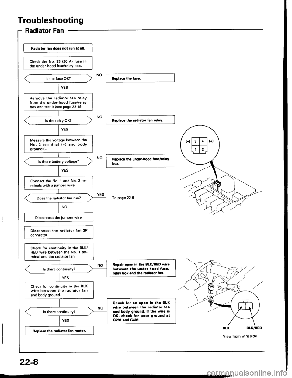
Radiator Fan
Redi.to. fan doo3 not run at all.
check rhe No. 33 {20 A) fuse inthe under-hood luse/relay box.
Remove the radiator lan r€layfrom the under-hood Iuse/relaybox and test it (see page 22-19).
Raplaca tha radiator tln rahy.
Measure the voltage between theNo. 3 terminal (+) and bodyground {-}.
ls therg battery voltag€?
Connect the No. 1 and No. 3 ter-minals with a jumper wire.
Does the radiator Ian run?
Chock for continuity in the BLK./RED wire between the No. 1 ter-minal and the radiator fan.
R.p.ir opdr in th. 8LK/RED wir.batwaon th. unda.-hood fut./ralay box rnd tha radirtor f.n.
Check for continuity in th€ BLKwire between the radiator {anand body ground.
Ch.ck to..n op.n in th. BLKwirc batwaan th. rldirtor hnlnd body ground, lf tha wita i!OK, chack tor poor gtound rtG2ol lnd GiOl.
Rephco tho radi.tor frn motor.
To p3ge 22-9
22-A
Page 1078 of 1413
Troubleshooting
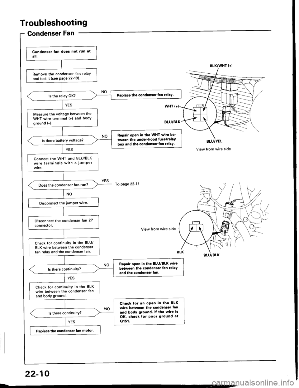
Condenser Fan
BLU/YEL
View lrom wire side
Remove the condenser fan relay
and test it (see page 22-19).
Replaco the condan3ar frn rclay.
Measure the voltag€ betwe€n the
WHT wire terminal (+) and bodyground (-).
Replir opcn in tho WHT wiro bo-
twoen tha undor-hood fura/Jolay
box rnd tha condonr.rlan rclay.
Connoct the WHT and BLU/BLK
wire terminals with a jumPer
Does the condenser fan run?
Check for continuity in the BLU/
BLK wire between the condenser
Ian relay and the condenser fan
Reprir op€n in th. BLU/BLK wiro
batwcen the condenrai lan rolay
and the condcntor ftn
Check for continuity in the BLK
wire between the condenser fan
and body ground.
Check fot.n op.n in tho BLK
wire botween the condental trn
and bodv g.ound. It the wiro i3
OK, chock lor Poo. ground rt
G151.
Raplaco the condon36r fan motor.
BLK/WHT l+l
10 page 22-11
View from wire side
BLU/BLK
22-10
Page 1079 of 1413
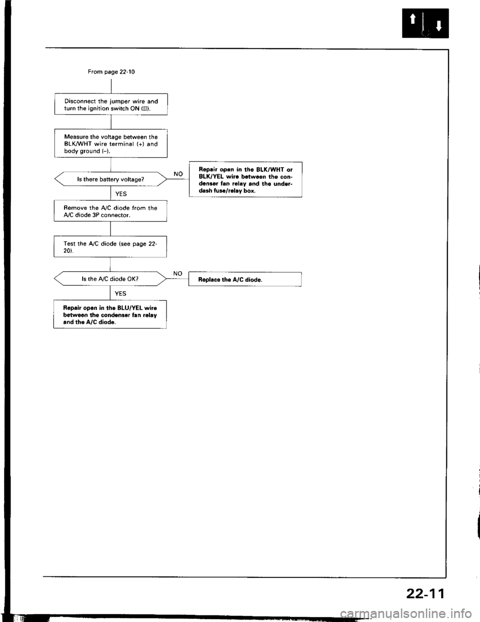
From page 22-10
Disconnect the iumper wire andturn the ignition switch ON (ll).
Measure the voltage between theBLK/WHT wire terminal (+) andbody ground (-).
Reptir open in tha BLK/WHT o.BLK/YEL wire betwoon tho con-den3o. f.n rel.y and tho unde.-dash tus6/rel.y box.
Remove the iay'C diode from theAy'C diode 3P connector.
ls the A,/C diode OK?
Reprir op6n in th. BLU/YEL wirebetwocn tho conden3er tsn reltv.nd tho A/C diod€.
22-11
Page 1080 of 1413
Troubleshooting
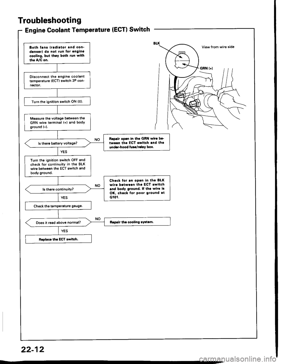
Bolh tanr lradiltor and con-
dan.arl do not run fot anginacooling. bul th.y bolh tun whh
th. A/C on.
Disconnect tho engino coolanltemporsture (ECT) switch 2P con-
n6ctor.
Turn rhe ignition switch ON (ll).
Measure th€ voltago botw€en th6
cRN wire terminal (+) and bodyground {-}.
R.p.ir op.n in ih. GRN wir. b.-
tw..n th. ECT .wilch .nd th.
undrr.hood ful./t l.y box.
Turn the ignition switch OFF and
check lor continuity in the BLK
wire beMeen the ECT switch and
body ground.
Ch.ck tor.n op.n in th. BLK
wir. b.lw.!n th. ECT .witch.nd body ground. It th. wit. i.
OK, chacl lor poor Oround tt
G10r.
Do€s it road above normal?
22-12
Page 1082 of 1413
Troubleshooting
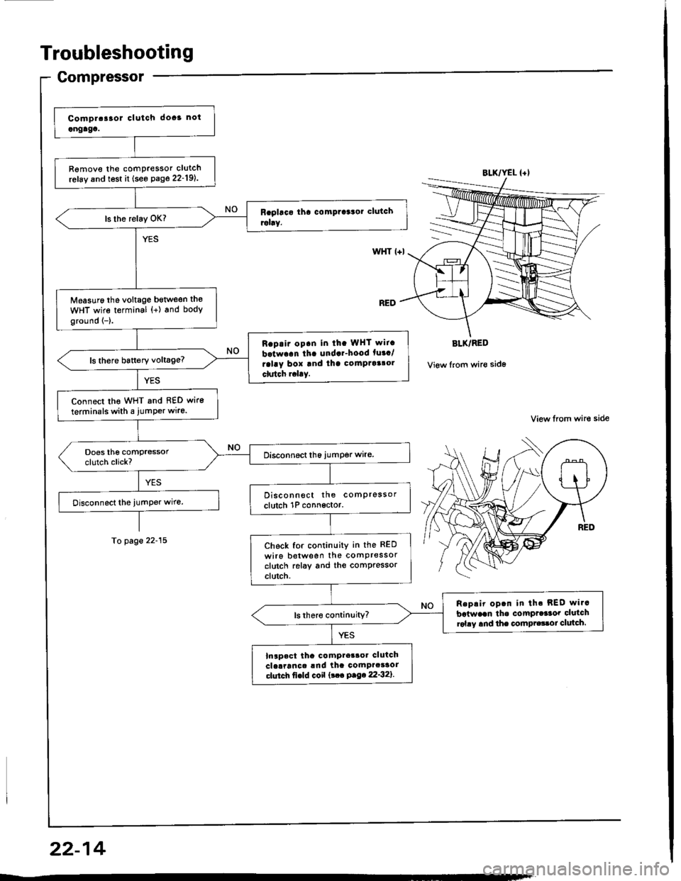
Gompressor
R6move the comPressor clutch
refay and test it (see Page 22-19l..
Measuro the voltage bgtlveen th€
WHT wire terminal {+) and body
ground {-}.
Rap.ir op.n in ih. WHT wit.
batwaan tha undar-hood fuaa/
ralay box and thg comptaalol
clutch r.l.y.
Connect tho WHT and 8€D wire
terminals with a jumPer wire.
Disconnect the comPressor
clutch 1P connsctor.
Check for continuity in the RED
wiro botween the comPressorclutch relay and the comPressorclutch.
Replir op.n in th. REO wi.c
batwaan tho comPrdaor clutchrol.y and the compr.33oi clulch.
Inapact tha compter3oa clutchclelranca !nd ihc comPacaaorctutch fi€ld coil {!.. P.9.22'32}.
BLK/YEL {+l
WHT l+l
BLK/RED
View from wir€ side
View lrom wire side
To page 22-15
22-14
Page 1083 of 1413
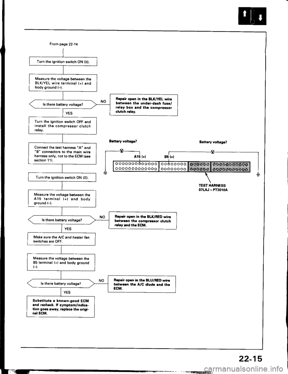
Frcm page 22-11
Bdt ry vohro.?
_@_____-l
Turn the ignition switch ON (lI).
M€asure the voltage betweon th6BLK/YEL wire terminsl {+) andbody ground (-).
R.p.i. opcn in th. 3LX/YEL wirrbalwarn tha undar.da3h tuaa/.clay box and iha como.aaao.clutch rahy.
ls there battery voltage?
Turn the ignition switch OFF andinstall the comprossor clutchrelay.
Connect the test harness "A" and"8" conoectors to th6 main wireharness only, not to the ECM (s6gsection 11).
Turn th6 ignition switch ON (II).
Measure the voltagG between theA15 terminal (+) and bodyground (-1.
R.prir op.n in th. BLK/RED wirtb.twran the compraa.or clotch..1.y .nd th. ECM.
Make sure the A/C and heate. tenswitch6s are OFF.
Measure tho voltage b€tween the85 terminsl (+) and body ground(-).
R.p.ir op.n in th. BI-U/RED wir.b.tw.rn th. A/C diod. .nd th.CCM.
Sub.titute r known-good ECMand rocheck. lt lymptom/indicr-tion go€3 rwry, rapbca th. origi-nrl ECM.
Blttary vohago?
r_--@_Bs {+)
TEST HARNESS07t4, - PT3010a
" , -1llltf,'tfrSfiiwiafi
22-15
Page 1085 of 1413
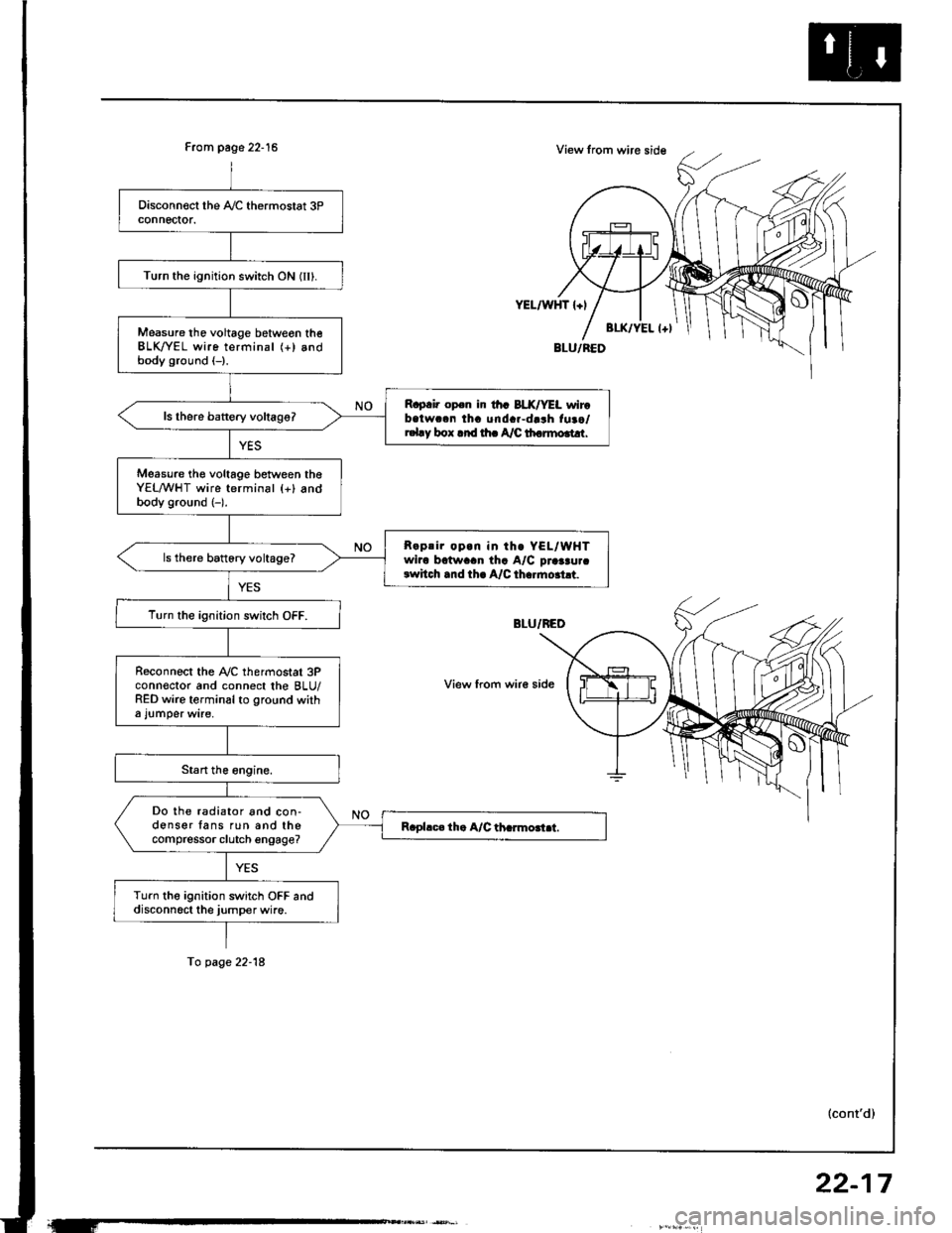
From page 22-15
Turn the ignition switch ON (IIl.
Measure tho voltage betweon theBLK/YEL wire terminal (+) andbody ground (-).
R.p.i. op.n ir th. BLX/YEL wirobatwc.n tha unda.-darh fuao/r.l.y box .rd rh. A/C th.rmo.t!r.
Measure th€ voltage between theYEL/WHT wire terminal {+} andbody ground (-).
R.prir op.n in th. YEL/WHTwiro bctwaan tha A/C praaau.crwhch .nd th. A/C th..mo.ht.
ls there battory voltage?
T!rn the ignition switch OFF.
R€connect the Ay'C thermostat 3Pconn€ctor and connect the BLU/RED wire terminal to ground witha l!mper wire,
Do the radiator and con-donser fans run and thecompressor clutch engage?
Turn the ignition switch OFF anddisconn6ct the jumper wire.
YEL/WHT l+l
View from wir€ side
To page 22-18
(cont'd)
22-17