body HONDA INTEGRA 1994 4.G Workshop Manual
[x] Cancel search | Manufacturer: HONDA, Model Year: 1994, Model line: INTEGRA, Model: HONDA INTEGRA 1994 4.GPages: 1413, PDF Size: 37.94 MB
Page 1307 of 1413
Switch Test
CAUTION:
a All SRS el6ctrical wiring harnossos are covarod withyellow inaulation.
a Beforo disconnecting any pan ot the SRS wire har-neaa, connoct ths short connector(s).a Roplace the entil€ afloctod SRS harne$ a$6mbly ifit has an open circuit or dsmagad wlring.
NOTE; The original radio has a coded theft protection
circuit. Be sure to get the customer's code number before- disconnecting the battery.- removing the No. 32 {7.5 A) fuse lrom the under-hoodtuse/relav box.- removing the radio.
After service, reconnect power to the radio and turn iton. When the word "CODE" is displayed, enter the cus-tomer's 5-digit code to restore radio operation.
1. Disconnect the battery negative cable, then discon-nect the positive cable.
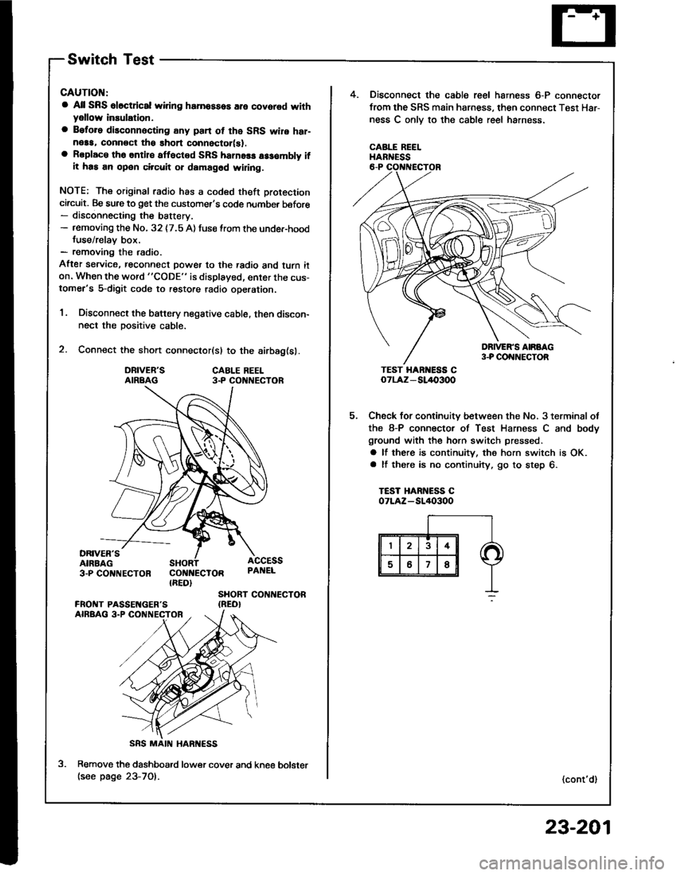
2. Connect the short connector(sl to the airbag(sl.
DRIVER'SAIRBAGCABLE REEL3.P CO NECTOR
DRIVER'SAIRBAG3-PCO'TNECTOR COI{NECTOR{RED}
ACCESSPAI{EL
SHORT CONTIECTOR{REO}
Remove the dashboatd lower cover and kne€(see page 23-701.
5.
4. Disconnect the cable reel harness 6-P connector
from the SRS main harness, then connect Test Har-
ness C onlv to the cable reel harness.
CABLE REELHARNESS
TEST HAR ESS CoTLAz - SL/l{,3OO
Check for continuity between the No, 3 terminal ot
the 8-P connector of Test Harness C and body
ground with the horn switch pressed.
a lf there is continuity, the horn switch is OK.a lf there is no continuity, go to step 6.
TEST HARNESS COTLAZ-SI/I()3OO
(cont'd)
bolster
23-201
Page 1316 of 1413

Rear Window Defogger
Function Test
CAUTION: Be carelul not to scratch 01 damago ths
defogger wires with th€ tsster probe.
1 . Check for voltage between the positive terminal and
body ground with the ignition switch and the delog-
ger switch ON. There should be battery voltage.
a lf there is no voltage, check for
- laulty detogger relay.- faulty defogger switch.- faulty integrated control unit.- an open in the BLK/GRN wire
a lJ there is baftery voltage, go to step 2.
NEGATIVE TERMIiIALPOSITIVE TERMINAL
Turn the rear window detogger switch OFF, Check
for continuity between the negative terminal and
body ground.
a It there is no continuity, check to. an open in the
defogger ground wire.
a ll there is continuity, go to step 3.
Touch the voltmeter positive lead to the halfway
point of each defogger wire, and the negative lead
to the negative terminal.
There should be apptoximately 6 V with the ignition
switch and defogger switch ON.
a lf the voltage is as specified, the defogger wire
is OK.
a lf the voltage is not as specified. repai, the defog-
ger wire:
lf it is more than 6 V, look for the damage on
the negative half on the grid.
- lf it is less than 6 V. iook for the damage on
the positive half of the grid.
Defogger Wires Repair
NOTE: To make an eftective repair. the broken section
must be no longer than one inch.
1 . Lightly rub the area around the break with line steel
wool, then clean it with alcohol.
2. Carefullv mask above and below the broken portion
of the defogger wire with cellophane tape.
Using a small brush, apply a heavy coat of silver con-
ductive paint extending about 3 mm ( 1/8 inl on both
sides of the break. Allow 30 minutes to dry.
NOTE: Thoroughly mix the paint before use.
Check for continuity in the repaired wire.
Apply a second coat of paint in the same way.
it drv three hours betore removing the tape.
4.
OPEN
23-210
tLet
Page 1320 of 1413
Moonroof
Function Test
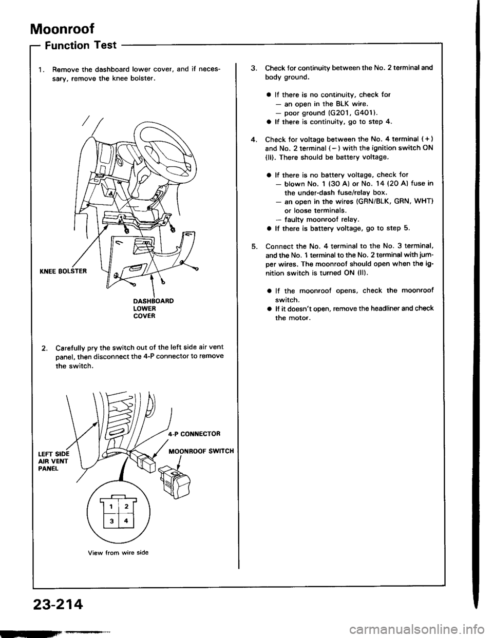
Remove the dashboard lower cover,
sarv, remove the knee bolste..
and if neces-
KNEE BOLSTER
DASHBOARDLOWERCOVER
2. Carefully pry the switch out of the left side air vent
panel, then disconnect the 4-P connector to remove
the switch.
4-P CONI{ECTOR
MOOi{ROOF SWITCH
View from wire side
.r--r
ll l2lf--T� --t
l314l
23-214
Check Jor continuity between the No. 2 terminal and
body ground.
a ll there is no continuity, check for- an ooen in the BLK wire.- poor ground (G201 , G4Ol ).
a lf there is continuity, go to step 4.
Check tor voltage between the No. 4 terminal ( + )
and No. 2 terminsl { - ) with the ignition switch ON
{ll). There should be battery voltage.
a lf there is no baftery voltage, check tot- blown No. 1 (3o Al or No. 14 {20 A) fuse in
the under-dash tuse/relay box.- an open in the wires (GRN/BLK, GRN, WHT)
or loose terminals.- faulty moonroof relay.
a lf there is battery voltage, go to step 5.
Connect the No. 4 terminal to the No. 3 terminal,
and the No. 1 terminal to the No, 2 terminal with jum-
per wires. The moonroot should open when the ig-
nition switch is turned ON (ll).
lf the moonroof ooens, check the moonroof
switch,
ll it doesn't open, remove the headlinet and check
the motor.
4.
Page 1325 of 1413
FunctionTest
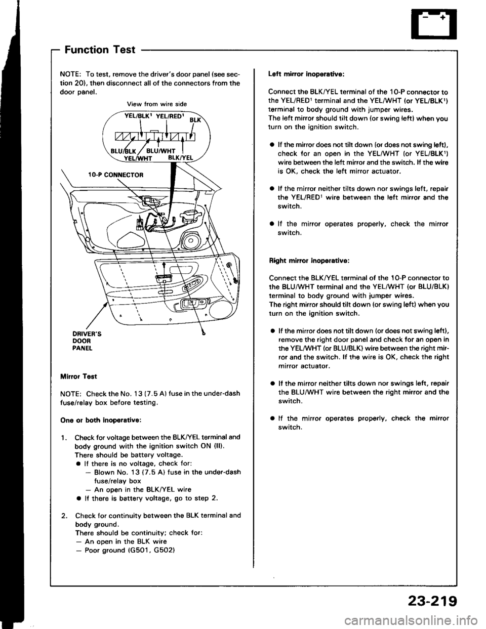
NOTE: To test, remove the driver's door panel (see sec-
tion 20), then disconnect all of the connectors from the
door oanel.
Miror Tost
NOTE; Check the No. 13 (7.5 A) tuse in the under-dash
fuse/relay box before testing.
Ono or both inop€rativa:
1. Check for voltage between the BLKIrEL terminal 8nd
body ground with the ignition switch ON (ll).
There should be battery voltage.
a lf there is no voltage, check tor:- Blown No. 13 {7.5 A) fuse in the under-dash
fuse/relav box- An ooen in the BLK/YEL wire
a It there is battery voltage, go to step 2.
2. Check for continuity between the BLK terminal and
body ground.
There should be continuity; check Jor:- An ooen in the BLK wire- Poor ground (G501, G5O2)
View from wire side
Loft mirror inopsrative:
Connect the BLK/YEL terminal of the 10-P connector to
the YEL/RED1 terminal and the YEL/WHT (or YEL/BLKr)
terminal to body ground with jumper wires.
The left mirror should tilt down (or swing leftl when you
turn on the ignition switch.
a lf the mirror does not tilt down (or does not swing leftl,
check Jor an open in the YEL/WHT (or YEL/BLK1)
wire between the left miffor and the switch. It the wir€
is OK, check the left mirror actuator.
a lf the mirro. neither tilts down nor swings left, repair
the YEL/RED1 wire between the left mirror and the
switch.
a lf the mirror operates properly, check the mirror
swatch.
Right mirror inoporative:
Connect the BLK/YEL terminal of the 1O-P connector to
th€ BLU/WHT terminal and the YEL/WHT {or BLU/BLK)
terminal to body ground with iumper wires.
The right mirror should tilt down (or swing left) when you
turn on the ignition switch.
a lf the mirror does not tilt down (or does not swing left),
remove the right door panel and check for an open in
the YELMHT (or BLU/BLK) wire between the right mir-
ror and the switch. lf the wire is OK. check the right
mtrror actualor.
a ll the mirror neither tilts down nor swings lelt, repair
the BLUMHT wire between the right mirror and the
switch.
a lf the mirror operates properly, check the mirror
swatch.
23-219
Page 1380 of 1413
Sensor Inspection
CAUTION: Tak€ €xtra care whon painting or doing
body work in the ar€a bslow th6 dalhboard.
Avoid dirost exposure ot lh6 sonsors or wiring to hestguns, wolding, or spraying equipmont.
Di3connact both the nogativo and po3itivo b!ftery
cable3.
Connsct tho short conneclor(s) before working
bslow the da3hboard or nsar lhe dash sen3o.3.
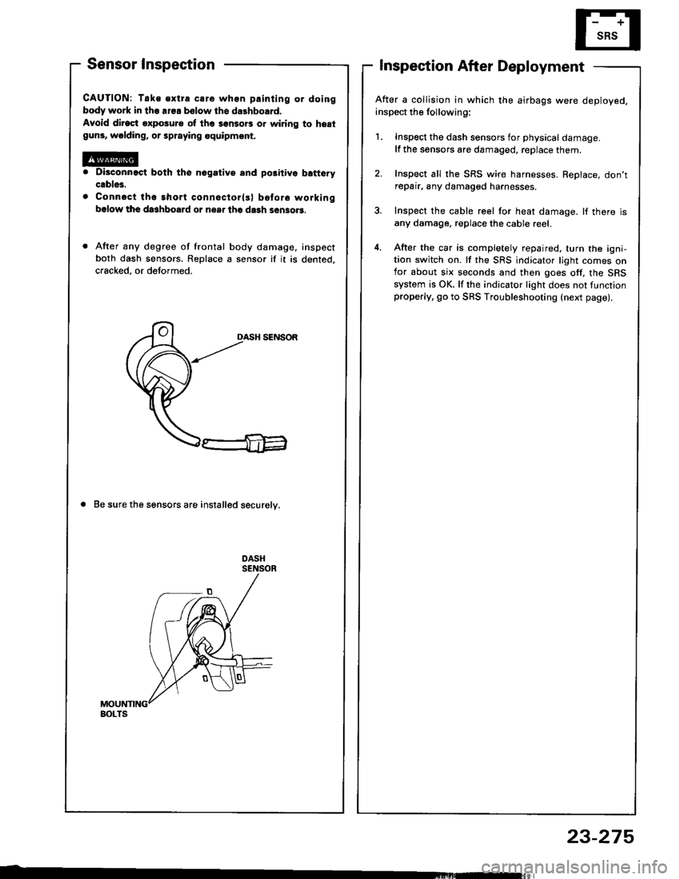
After any degree of frontal body damage, inspect
both dash sensors. Replace a sensor if it is dented,
cracked, or deformed.
DASH SENSOR
a Be sure the sensors are installed securelv,
Inspection After Deployment
After a collision in which the airbags were deployed.
inspect the following:
1. Inspect the dash sensors for physical damage.
lf the sensors are damaged, replace them.
2. Inspect all the SRS wire harnesses, ReDlace, don'trepair, any damaged harnesses.
3. Inspect the cable reel for heat damage. lf there is
any damage. replace the cable reel.
4. After the car is completely repaired. turn the igni-tion switch on. lf the SRS indicator light comes onfor about six seconds and then goes off, the SRS
system is OK. lf the indicator light does not functionproperly, go to SRS Troubleshooting (next page).
BOLTS
23-275
Page 1384 of 1413
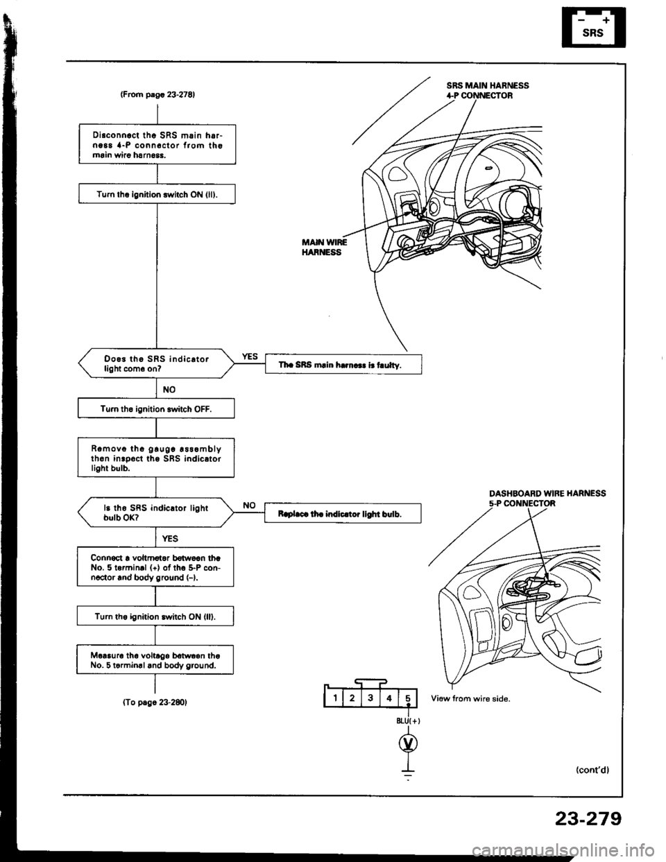
SRS MAIN HABNESS(From plgr 23.27E1
DASHBOARD WIFE HARNESS5-P CONNECTOR
8tU{ +
@
I:
Disconnoct tho SRS m.in h6,-ng88 {-P conn6clor f,om thomrin wiao harn6$.
Tum lhq ignition switch ON (lll.
Doo3 tho SRS indic.torlight com6 on?Th. SRS rnlin h..n... i.t ulty.
Tu.n tho ignition switch OFF.
Romovo tho g!u0c !ss.mblyth6n inrpoct ths SBS indicatorlight bulb.
Raplaca lh. indlc.toi llOht birlb.
Connoct ! voltmotoa bdwoln thrNo. 5 lormin.l (+) of tho 5-P con-noctor rnd body ground (-).
Turn the ignition switch ON (ll).
Moaauro tha voltrgo bolwcon thaNo. 5 termin.land body g.ound.
MAIN VNREHARNESS
(To p.go 2+280)
23-279
Page 1385 of 1413
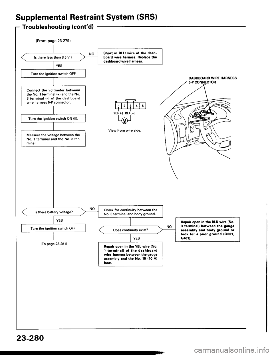
(From page 23-279)
Short in 8LU wire ol the da.h-borrd wi.o halno3s. Roplaca thad.3hbosrd wiro ha.no$.ls there lesslhan 8.5 V ?
Turn the ignition switch OFF
Connect tho voltmeter betweenthe No. 1 terminal (+) and the No.3 terminal (-) of the dashbo€rdwire harness 5-P connector.
Turn the ignition switch ON (ll).
Measure the voltage between theNo. 1 terminal and th€ No.3 ter-mrnal,
Ch6ck for continuity between th6No. 3 terminal and body ground.ls there battery vohage?
R.prir opcn in tho BLK wir. (No.
3 tarmin!l) batwaan th. gluga
araambly and body ground otlook tor. poor ground 1G201,cilol I.
Turn the ignition switch OFF.
Rcprir open in th. YEL wi.o lNo.t t6rminall of the d.3hbo.rdwir6 hamer! batwaen tho gtugo
r3s6mblv rnd tho No. 15 ll0 Alfu36.
Supplemental
Troubleshooting(cont'd)
{To page 23-281}
RestraintSystem (SRSI
DASHBOARD WIRE HARNESS
View lrom wire side.
YELI+, BLK{-I
23-280
Page 1386 of 1413
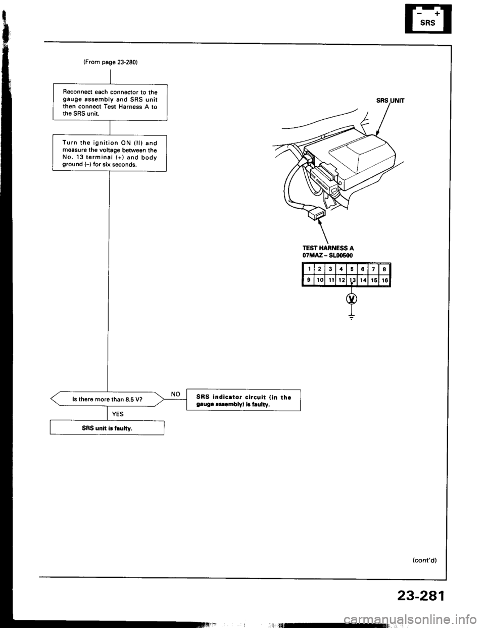
(From page 23-280)
Reconnect each connector to thegauge assembly and SRS unitthen connect Tgst Harness A tothe SRS unit.
Turn the ignirion ON 0l) andmoasure th€ voltage betwegn theNo. 13 terminal (+) and bodyground (-) tor six seconds.
SBS indic.tor circqit {in th.e.ug. r.t mblv, i. hulty,ls th€r6 more than 8.5 V?
TEST HARNESS A07MAZ - S!IX)s{X'
48
910Itl213l41516
23-2a1
,;l tflEt$ r'
Page 1387 of 1413
Supplemental Restraint System (SRSI
Troubleshooting (cont'dl
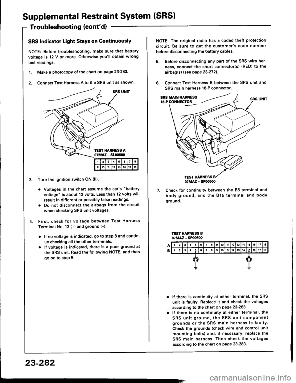
SRS Indicator Light Stays on Continuously
NOTE: Before troubleshooting, make sure that battery
voltage is 12 V or mo.e. Otherwise you'll obtain wrong
test readings.
1. Make a photocopy of the chart on page 23-283,
2. Connect Test Harness A to the SRS unit as shown.
Tu.n the ignition switch ON (lll.
. Voltages in the chart assume the car's "battery
voltage" is about 12 volts. Less than 12 volts will
result in different or possibly talse readings.
. Do not disconnect the airbags ftom the circuit
when checking SRS unit voltages.
First, check for voltage between Test Harnoss
Terminal No. 12 (+) and ground (-).
. lf no voltage is indicated, go to step I and contin-
ue checking all the other terminals.
o lf vottsge is indicated, there is a poor ground at
the SRS unit. Read the following NOTE, and then
go on to step 5.
I21I
tolll2t3tlrt
23-282
TEST HANNESS
NOTE: The original .adio has a coded theft protection
circuit. Be sure to get the customer's code number
before disconnecting the battery cables.
Before disconnecting any pan of the SRS wire har-
ness, connect the short connecto(s) {RED) to the
airbag(s) (see page 23-2721.
Connect Test Harness B between the SRS unit and
SRS main harn€ss 18-P connector.
7. Check for continuitv between the 85 terminal and
body ground, and the Bl5 terminal and body
ground.
TEST HARNESS B07MAZ - SPqrS{X)
lf there is continuity at either terminal, the SRS
unit is faulty. Replace it and check the voltages
according to the chan on page 23-283.
lf there is no continuity at either terminal, the
SRS unit ground, the SRS unit component
grounds or the SRS main harness is faulty
Check the grounds (check wire and control unit
mounting bolts) and, if necessary, replace th€
SRS main harness. Then check the voltages
according to the chart on page 23-283
Page 1389 of 1413
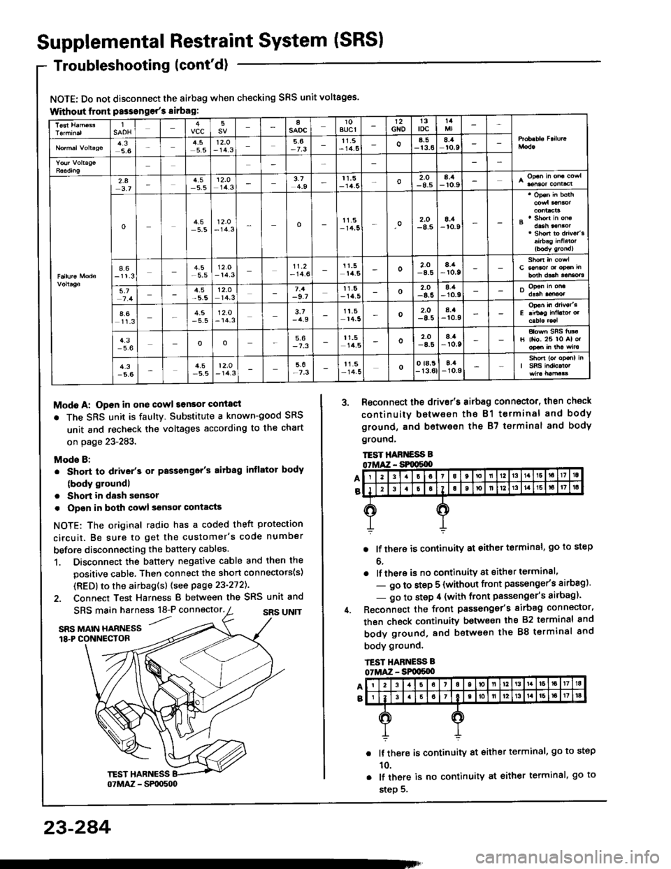
Supplemental Restraint System (SRSI
Troubleshooting (cont'd)
NOTE: Do not disconnect the airbag when checking SRS unit voltages.
Without lront Passongor's sirbag:
Modo A: Open in one cowl sonsor conlact
r The SRS unit is faultY. Substitute a known-good SRS
unit and recheck the voltages according to the chart
on page 23-283.
Mods B:
. Short to driver's or Passonger's aitbag inflator body
(body groundl
. Short in dash sonsor
. Opsn in both cowl sgnsor contacts
NOTE: The original radio has a coded theft protection
circuit. Be sure to get the customer's code number
before disconnecting the battery cables.
1. Disconnect the battery negative cable and then the
positive cable. Then connect the short connectots(s)
(RED) to the airbag(s) (see page 23-272).
2. Connect Test Harness B between the SRS unit and
A
B
SRS main harness 18-P connector.SRS UN]T'...SRS MAIN HARNESS18.P CONNECTOR
3. Reconnect the driv€r's airbag connector, then check
continuity between the B1 terminal and body
ground, and b€twesn the 87 terminsl and body
grounq,
TEST HABT{ESS B
. lf there is continuity at either terminal, go to step
o.
. lf there is no continuity at sither terminal'
- go to step 5 (without front passonge/s airbag)'
- go to step il (with front passenger's airbag)'
Reconnect the front passonger's sirbag connector,
then check continuity betwo€n ihs 82 t€rminal and
body ground, and between the 88 terminal and
body ground.
lf there is continuity at either terminal, go to step
10.
lf there is no continuity at either terminal, go to
step 5.
lSAOHvcc58saoc10BUCI12Gto13toct4
4,35.65.512.O- 14.35,6-7.311.5- 14,5oa_5-13.68.:aro.9
2.43.74.55.5
't2.o
14.33.74.911,5-14.5o2.O-8.58.4-r0.9
o4.55,512.O- 14.3o11.5-14,5o2.O-8.58./a-r0.9
4.6-11.3-5.512.O- 14.311.2- 14.611.514,5o2.O8./t-r0.9
5.74.5t2.o14,3-9.7tt.5- 14_5o-8.58.1-10.9
4.611.34.5- 5.512.0- 14.33.7-4.91t.514.5o2.O-8.5a.a-r0.9
4.3oo5,6-7.311.514,5o2,O8.it,r0.9H ll{o. 26 lo Al o.
4.3-5.64.5-5.512.O- 14.3-7.3t1.5- 14-5oo ta,5- 13.0tE,4-10.9
23-284