body HONDA INTEGRA 1994 4.G Workshop Manual
[x] Cancel search | Manufacturer: HONDA, Model Year: 1994, Model line: INTEGRA, Model: HONDA INTEGRA 1994 4.GPages: 1413, PDF Size: 37.94 MB
Page 972 of 1413
Seats
Front Seat Removal
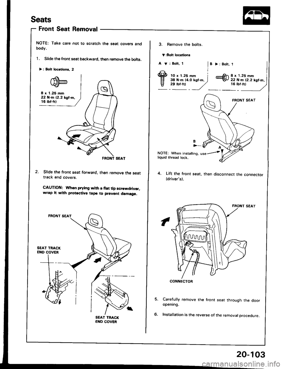
NOTE: Take care not to scratch the seat covers andbodY.
1 . Slide the lront seat backward, then remove th6 bohs,
Slide the front seat forward, then romove the seattrack end covers.
CAUTlOltl: When prying wlth E flat tip scr.wddvor,w.ap lt whh protactive tapo to prevont damago,
> i Eolt locltlon.. 2
3. Remove the bolts.
V:Boh locatlong
A V : Bolt, 1
I'
> : 8olt,
@8 x '1.25 mm Iii i.:iiil..i'xst.^. I16:t'ftt
- /)
4.
NOTE: When insralling, use--iliquid thread lock.
Lift the front seat, then disconnect the connector(driver's).
Carefully remove the front seat through the dooropening.
Installation is the reverse of the removal procedure.
CONNECTOR
20-103
Page 973 of 1413
Seats
NOTE: Take care not to scratch the seat covers and
body.
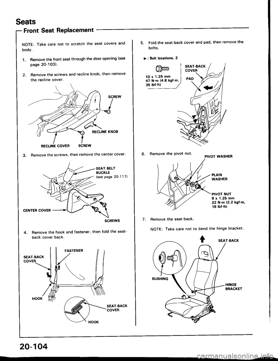
1. Remove the front seat through the door opening (see
page 20-1O3).
2. Remove the screws and recline knob, then remove
the recline cover.
RECLINE COVER SCREW
Remove the screws, then remove the center cover.
SEAT BELTBUCKLE{see page 2O'1 '1 7)
CENTER COVER
scREws
Remove the hook and fastener, then lold the seat-
back cover back.
20-104
Front Seat RePlacement
5, Fold the seat-back cover and pad, then remove the
bolts.
> : Bolt location., 2
lnnrnt Iv)* |lO x 1.25 mm i47 N'm 14.8 kgl ln, I"?"!."t _J
SEAT.gACKCOVER
PAO
6. Remove the Pivot nut.PIVOT WASHER
PLAINWASHER
PIVOT NUT8 r 1.25 mm22Nm12.2kgl'm,16 lbf.ftl
7.Remove the seat-back.
NOTE: Take care not tobend the hinge bracket.
+ sEAr-BAcK
Page 977 of 1413

Seats
Rear Seat Replacement
Hatchback
NOTE: Take care not to scratch the seat covers and
body.
1. Fold the seat-backs {orward.
2. Remove the clips, then fold the trunk mat.
V: Clip locations, 14
I
+ |
v/J
20-108
(see page 20-1Og)
SEAT.BACKS
TRUNK MAT
3. Remove the cliD pin on each side.
Slide the seat-backs outward, then remove the seat-
backs from the pivot bracket.
SEAT.BACK
SEAT-BACK PIVOTBRACKET
CLIP PIN
Page 1007 of 1413
Dashboard
Replacement (cont'd)
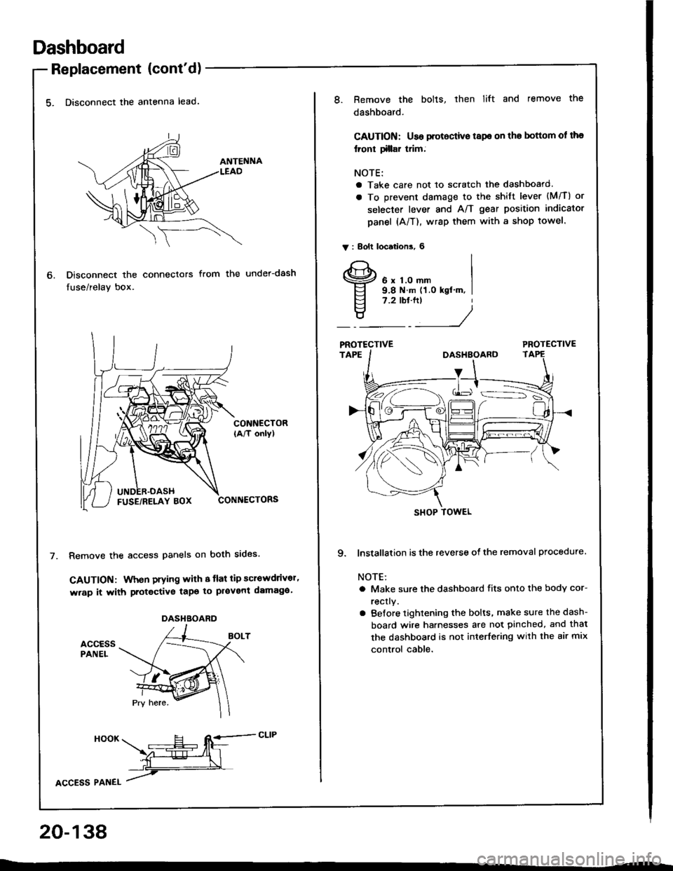
5. Disconnect the antenna lead.
Disconnect the connectors
fuse/relay box.
from the under-dash
CONNECTOR(A/T only)
CONNECTORS
Remove the access panels on both sides.
GAUTION: When prying with 8 tlat tip scrowdrivor'
wrap it with protective tapo to pl€vent damaga'
accEssPANEL
6.
DASHBOARD
HooK ___E-- RE=-cLrP
ffiL
lcCesS Plnel /
20-138
8.Remove the bolts, then lift and remove the
dashboard.
CAUTION: Use protoctive tspe on the bottom ol tha
lront tillar trim;
NOTE:
a Take care not to scratch the dashboard.
a To prevent damage to the shift lever (M/T) or
selecter lever and A/T gear position indicator
panel (A/T), wrap them with a shop towel.
V : Bolt locations, 6
6 x 1.0 mm9.8 N.m (1.0 kgt'm, I7.2 tbt.ftt
____/
PROTECTIVE
9. lnstallation is the reverse of the removal procedure
NOTE:
a Make sure the dashboard fits onto the body cor-
rectly.
a Before tightening the bolts, make sure the dash-
board wire harnesses are not pinched, and thal
the dashboard is not interfering with the air mix
control cable.
SHOP TOWEL
Page 1009 of 1413
Bumpers
Front Bumper RePlacement (cont'd)
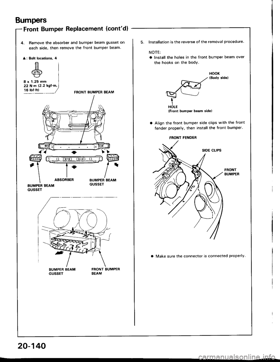
4. Remove the absorber and bumper beam gusset on
each side. then remove the front bumper beam.
: Eolt locotions. 4
E6rcr
8 r 1.25 mm
22 N.m (2.2 kgt'm, I't6 tbt fti _/FRONT BUMPER BEAM
ABSORBER
20-140
FRONT FEiIDER
Installation is the reverse of the removal procedure.
NOTE:
o Install the holes in the front bumper beam over
the hooks on the bodY.
FrBo*sidorHOLE(Front bumper b€am sidel
Align the front bumper side clips with the tront
fender properly, then install the front bumper.
FRONTBUMPER
a Make sure the connector is connected properly.
Page 1013 of 1413
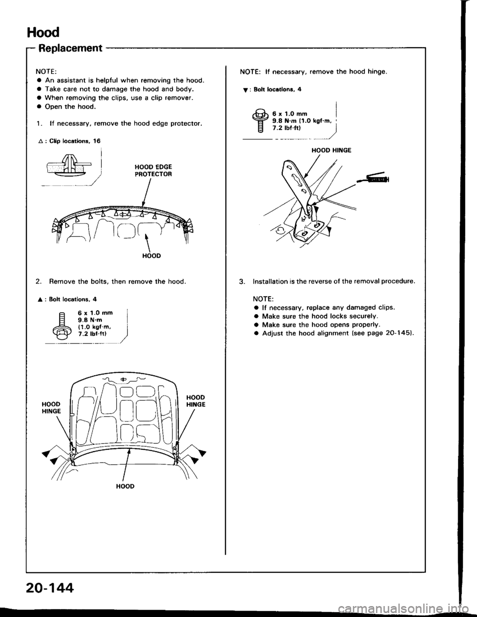
Hood
Replacement
NOTE:
a An assistant is helplul when removing the hood.
a Take care not to damage the hood and body.
a When removing the clips, use a clip remover.
a Open the hood.
1. It necessary, remove the hood edge protector.
: Clip loc.tions, 16
NOTE: It necessary, remove the hood hinge.
V : Boh locationa, 4
I3;;,iH"-,,., I
j .rtor"t
- )
HOOD EDGEPROTECTOR
\HOOD
2. Remove the bolts. then remove the hood.
: Bolt localions, 4
lnstallStion is the reverse of the removal procedure.
NOTE:
a lf necessary, replace any damaged clips.
a Make su.e the hood locks securely.
a Make sure the hood opens properly.
a Adjust the hood alignment (see page 20-1451.
6x1.0mm9.8 N'm{l.O kgl m,7.2 lbl.fr)
HOOD HINGE
n
r)
HOOD
20-144
Page 1014 of 1413
Adjustment
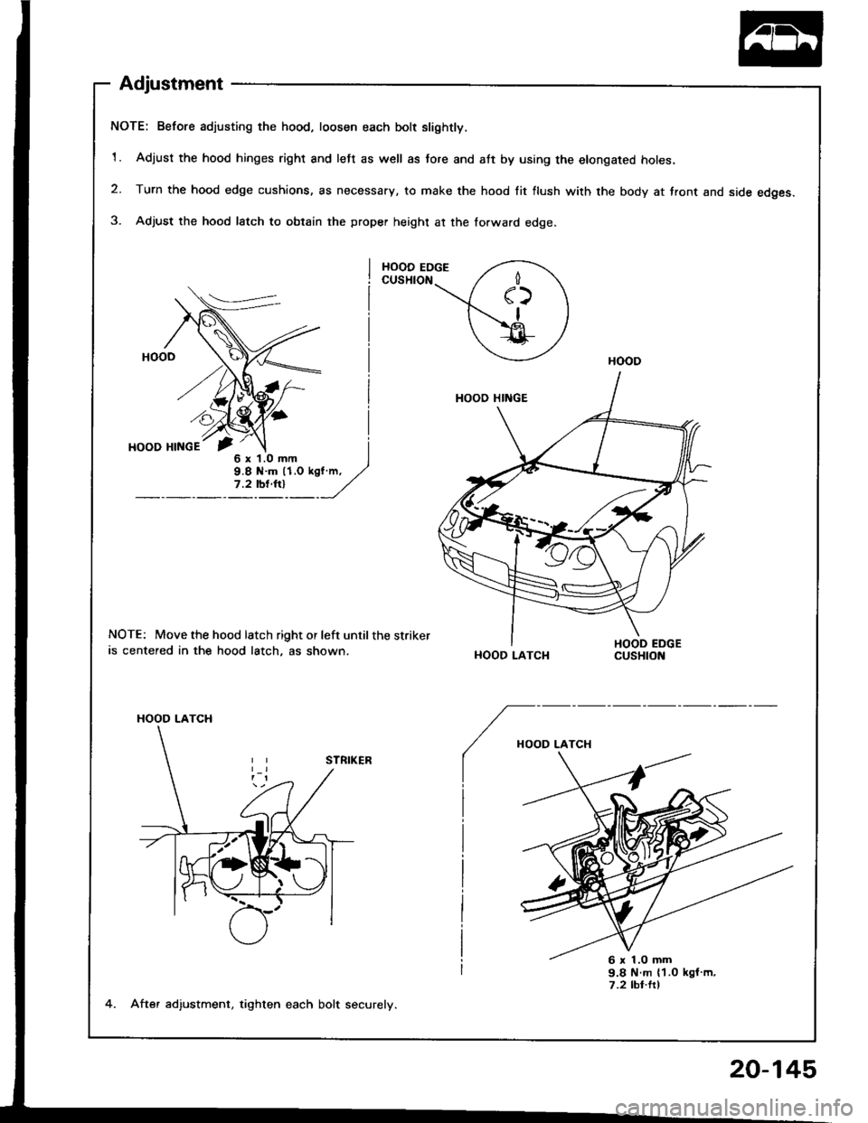
NOTE: Before adjusting the hood, loosen each bolt slightly.
1. Adjust the hood hinges right and left as well as tore and att by using the elongated holes.
2. Turn the hood edge cushions, as necessary, to make the hood lit flush with the body at front and side edges.
3. Adjust the hood latch to obtain the proper height at the forward edge.
NOTE: Move the hood latch right or left until the striker
is centered in the hood latch, as shown.HOOD LATCH
HOOD LATCH
6 r 1.o mm
4. After adiustment, tighten each bolt securely.
20-145
Page 1015 of 1413
Hatch
Replacement
NOTE:
a An assistant is helpful when removing the hatch.
a Take care not to damage the hatch and body.
a Take care not to scratch the hatch side trims and hatch
tnm paner.
a Open the hatch.
a Remove the high mount brake light {see section 23).
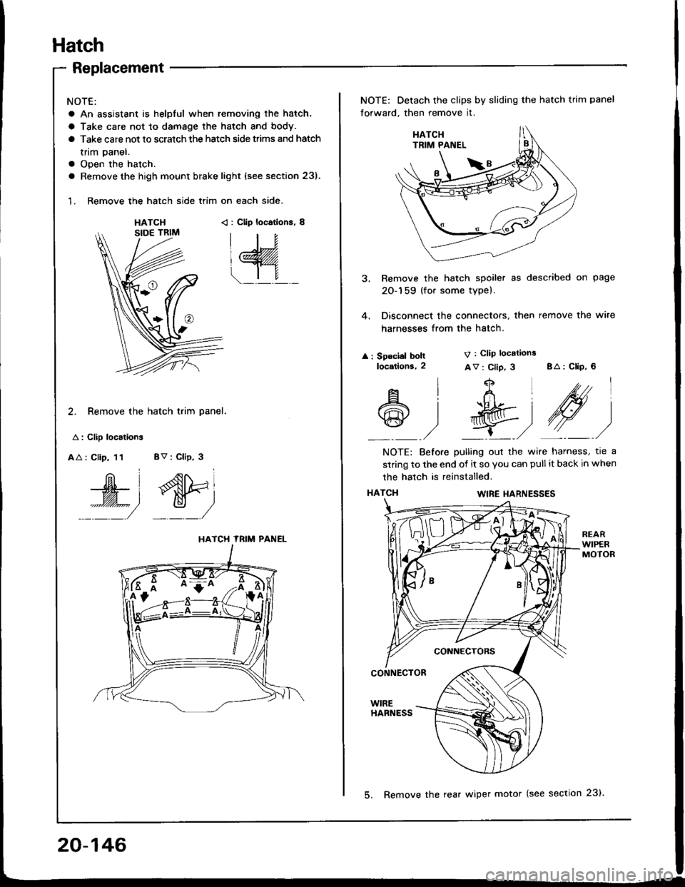
1. Remove the hatch side trim on each side.
HATCH< : Clip locations, 8
2. Remove the hatch trim panel.
A : Clip localions
AA : Clip, 11 BV : Clip, 3
W', dtri
::::/ _:_/
HATCH TRIM PANEL
NOTE: Detach the clips by sliding the hatch trim panel
forward, then remove it.
3. Remove the hatch spoiler as described on page
20-159 (for some type).
4. Disconnect the connectors, then remove the wire
harnesses from the hatch.
: Speclal boltlocetlons,2
V : Clip locations
Av : Clip, 3 BA: CliP, 6
4
t+Ltfrl
l'R@t
,/ L,/
A
@
l
)
NOTE: Before pulling out the wire harness, tre a
strinq to the end of it so you can pull it back in when
the hatch is reinstalled.
HATCI{WIRE I{ARNESSES
CONNECTORS
CONNECTOR
WIREHARNESS
20-146
5. Remove the rear wiper motor (see section 23).
Page 1017 of 1413
Hatch
Adjustment
NOTE:
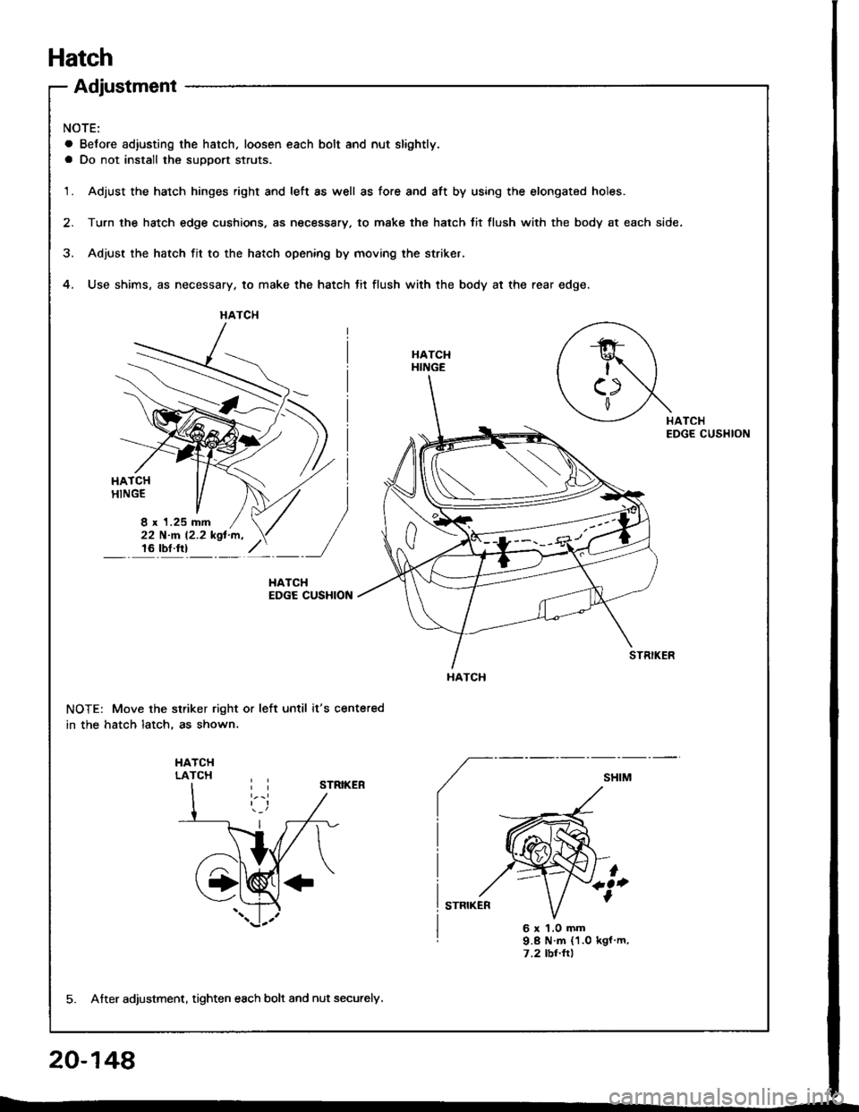
a Before ad,usting the hatch. loosen each bolt and nut slightly.
a Do not install the suDDort struts.
1.Adjust the hatch hinges right and left as well as fore and aft by using the elongated holes.
Turn the hatch edge cushions, as necessary. to make the hatch tit flush with the body at each side.
Adjust the hatch fit to the hatch opening by moving the striker,
Use shims, as necessary, to make the hatch tit flush with the body at the rear edge.4.
HATCHEDGE CUSHION
NOTE: Move the striker right or left until it's centered
in the hatch latch, as shown.
HATCHLATCH
t+Q.
6x1.0mm9.8 N m (1.0 kgl m,7 .2 tbt.trl
HATCH
8 x 1.25 mm
HATCH
5. Atter adjustment, tighten each bolt and nut securely,
Page 1018 of 1413
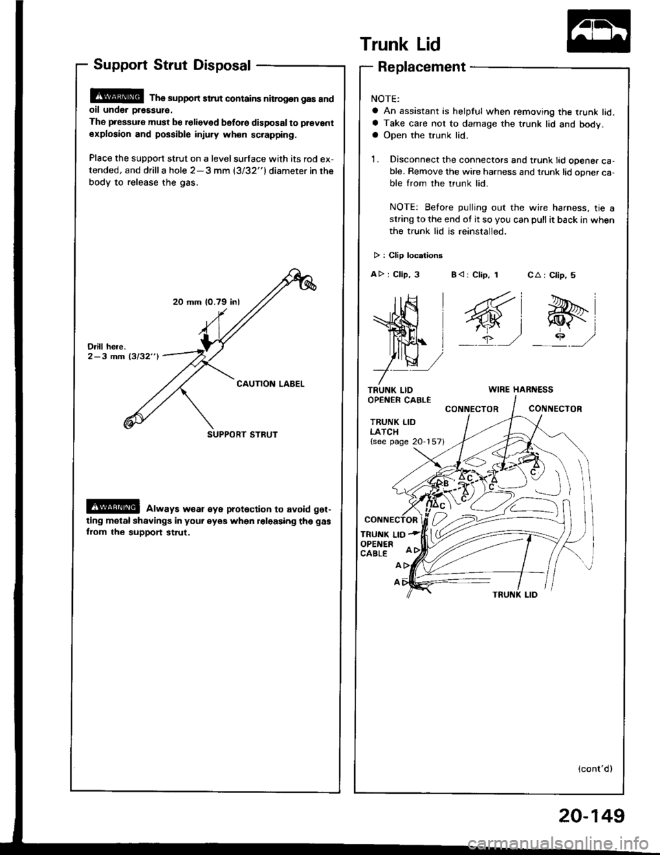
20 mm (O.79 inl
SUPPORT STRUT
Support Strut Disposal
@ Tha support strut contains nitrog.n gas andoil unde. pr€ssul€.
The pressure must be relieved bsfo.e disposal to prevant
explosion and possible injury wh€n sc.apping.
Place the support strut on a level surface with its rod ex-
tended, and drilla hole 2-3 mm (3/32"1diameter in the
body to release the gas.
@ always w€ar €ye prot6ction to avoid get-
ting motal shavings in your eyea when roloasing th€ gas
fiom the support st.ut.
Trunk Lid
TRUNK LIDOPEN€R CABLE
TRUNK LIDLATCH{see page 20-157}
TRUNK LIOOPENERCABLE
CA : Clip, 5
e-i
_rP ,/
Replacement
NOTE:
a An assistant is helpful when removing the trunk lid.a Take care not to damage the t.unk lid and body.a Open the trunk lid.
1. Disconnect the connectors and trunk lid opener ca-ble. Remove the wire harness and t.unk lid opner ca-ble from the trunk lid.
NOTE: Before pulling out the wire harness, tie astring to the end ot it so you can pull it back in when
the trunk lid is reinstalled.
> : Clip locationg
AD : Clip, 3 B< : Clip, 1
WIRE HARNESS
CONNECTORCONIIECTOR
A
A
(cont'd)
20-149