body HONDA INTEGRA 1994 4.G Workshop Manual
[x] Cancel search | Manufacturer: HONDA, Model Year: 1994, Model line: INTEGRA, Model: HONDA INTEGRA 1994 4.GPages: 1413, PDF Size: 37.94 MB
Page 1020 of 1413
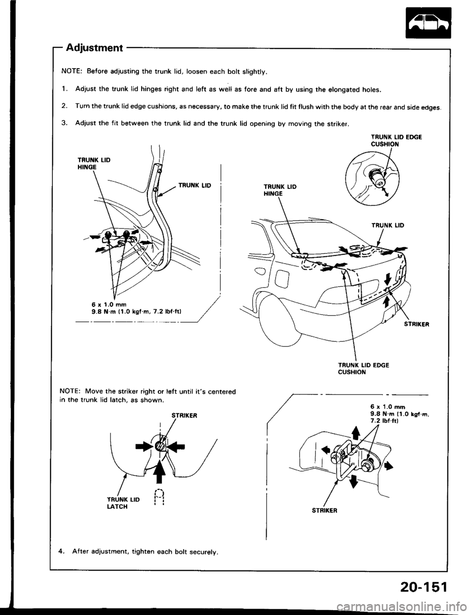
Adjustment
NOTE: Beto.e adjusting the trunk lid, loosen each bolt slightly.
1. Adjust the trunk lid hinges right and left as well as fore and aft by using rhe etongated holes.
2. Turn the trunk lid edge cushions, as necessary, to make the trunk lid fit flush with the body at the rear and side edges.
3. Adjust the lit between the trunk lid and the trunk lid opening by moving the striker.
TRUNK LID EDGECUSHION
NOTE: Move the st.iker right or left until it's centered
in the trunk lid lalch, as shown,6 x '1.0 mrn9.8 N m 11.0 lo,f.m,7.2 tbt.hl
/21
ft(M
Y4Y
TRUNI( LID
TRUNK LIDHINGE
6r1.Omm9.8 N.m 11.0 ksl m, 7.2 lbt'ft|
STRIKER
STRIKER
4. Atter adjuslment, tighten each bolt securelv.
20-151
Page 1024 of 1413
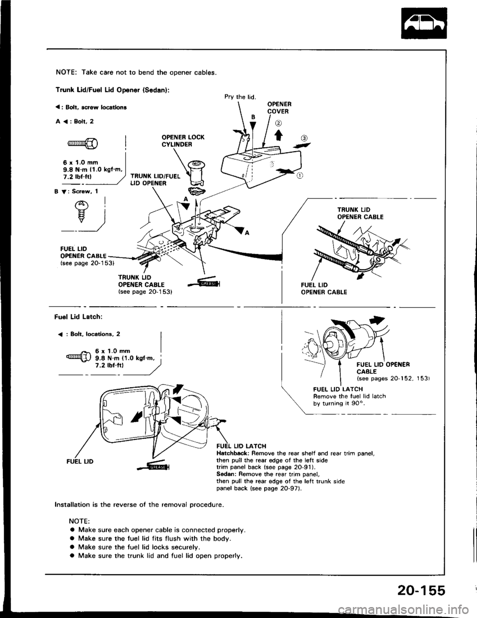
NOTE: Take care not to bend the opener cables.
Trunk Lid/Fuel Lid Oponer {Sodan}:
< : Bolt, scrow locatlon!
A<:Bolr,2
OPENER LOCKCYLINDER
TRUNK LID/FUELLID OPENER
B V: Scrow, 1
AI-}{- IH. I
_:_)
FUEL LID
Pry the ljd.OPENERCOVER
o
to-*rr*@
6 r 1.0 mm
()t
OP€NER CABLE(seo page 2O-153)
TRUNK LIDOPENER CABLE(see page 20-1 53)
9.8 N m 11.O kgl m,
Fuol Lid Lstch:
< : Boh, locotions, 2
6r1.0mm
FUEL LID OP€NERCAALE(see pages 20-152, 153)
9.8 N m 11.0 ksl'm, i7 '2 tbt'''l
------,//
FUEL LID
lnstallation is the reverse of the removal orocedure.
NOTE:
a Make sure each opener cable is connected properly.
a Make sure the fuel lid fits flush with the body.
a Make sure the tuel lid locks securelv.
a Make sure the trunk lid and fuel lid open properly.
LIO LATCHHatchbock: Remove the rear shelf and rear trim oanel.then pull the rear edge ot the lett sidetrim panel back (soe page 2O-91).Sodan: Remove the rear trim panel,then pull the rear edge of the left trunk sidepanel back {see page 2O-971.
FUEL LIO LATCHRemove the fuel lid latchby turning it 90o.
20-155
Page 1030 of 1413
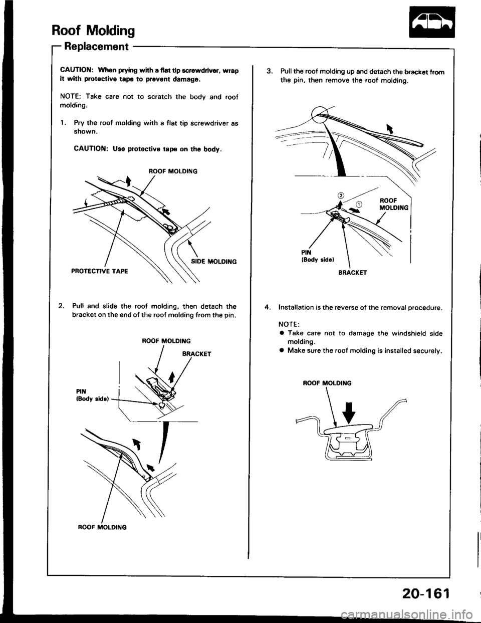
Roof Molding
Replacement
CAUTION: When prying with I flat tlp scrowddv€r, wrap
it with protoctivo tapo to pravent damag6.
NOTE: Take care not to scratch the bodv and root
molding.
1 . Pry the rool molding with a flat tip screwdriver as
snown.
CAUTlOfil: Use protoctivo rape on tho body.
SIDE MOLOII{G
Pull and slide the root molding, then detach the
bracket on the end of the roof molding from the pin.
PIN{Body ddq)
ROOF MOLDING
ROOF MOLDING
ROOF MOLDING
20-161
BRACKET
aPull the roof molding up and detach the bracket lrom
the pin, then remove the roof molding.
Installation is the reverse of the removal orocedure.
NOTE:
a Take care not to damage the windshield side
molding.
a Make sure the roof molding is installed securely.
4.
R(X)F MOLDING
Page 1031 of 1413
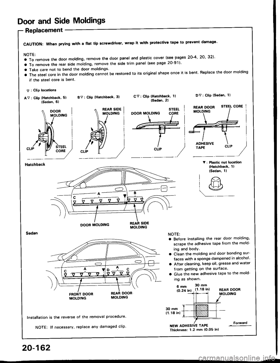
Door and Side Moldings
Replacement
CAUTION: When prying with 8 flal tip screwdriver, wrap it with protective tape to pr€vont damag€'
NOTE:
a To remove the doot moldlng, temove the door panel and plastic cover {see pages 2O-4' 2O' 32],'
a To remove the rear side molding, remove the side trim panel (see page 20-91)
a Take care not to bend the door moldings.
a The steel core in the door molding cann-ot be restored to its original shape once it is bent. Replace the door molding
if the steel core is bent.
V : Clip locations
av : cllp (Hatchb6ck, 5) BV: clip (Hatchback' 3)
V: Plastic nui locatlon(Hatchback, 1)(Sedan, 1)
CV: Cllp (Halchback, 1l{Sodan,2l
Dv: Clip lsodan, 1)
Hatchbsck
20-162
30 mm(1.18 inl
lnstallation is the reverse
NOTE: It necessary,
oJ the removal Procedure.
replace any damaged cliP.NEW ADHESIVE TAPE
Thicknoss: 1.2 mm lo.o5 inl
Forward
STEEL
CLIP
O'
lr>
r9
NOTE:
a BeJore instatling the rear door molding,
scrape the adhesive tape from the mold-
ing and body.
a Clean the motding and door bonding sur-
Jaces with a sponge dampened in alcohol'
a Atter cleaning, keep oil, grease and water
Jrom getting on the surface.
a Glue the new adhesive tape to the mold-
ing as shown.
6mm 30mm
ls 2f 61 . t.l.18 inlREAR DOORMOLDING
Page 1032 of 1413
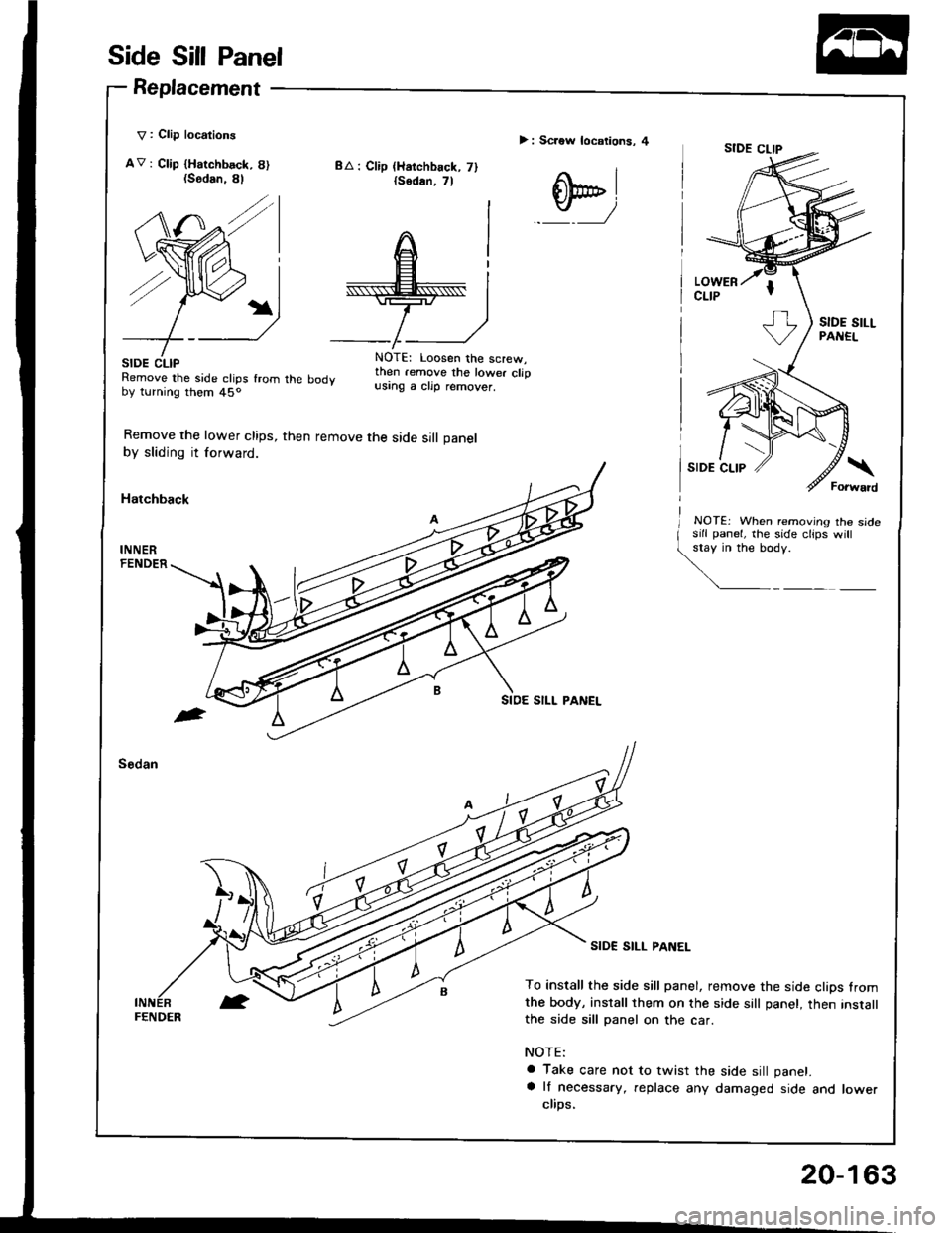
Side Sill Panel
Replacement
V : Clip locations
AV: Ctip {Harchbsck, 8){Sodan.
SIDE CLIPRemove the side clips fromby turning them 45o
Remove the lower clips,
by sliding it forward.
Hatchback
BA : Clip (Harchback, 7){sodan,7l
> : Screw locations, 4
q,
8l
/
rhe body
then remove the side sill panel
NOTE: Loosen the screw,then .emove the lower clipusing a clip remover.
NOTEj When removing the sidesill panel, lhe side clips will
\y':
SIDE SILL PANEL
To install the side sill panel, remove the side clips fromthe body, install them on the side sall panel, then instatlthe side sill panel on the car.
NOTE:
a Take care not to twist the side sill panet.
a lf necessary, replace any damaged side and lowerclips,
FENDER
20-163
Page 1033 of 1413
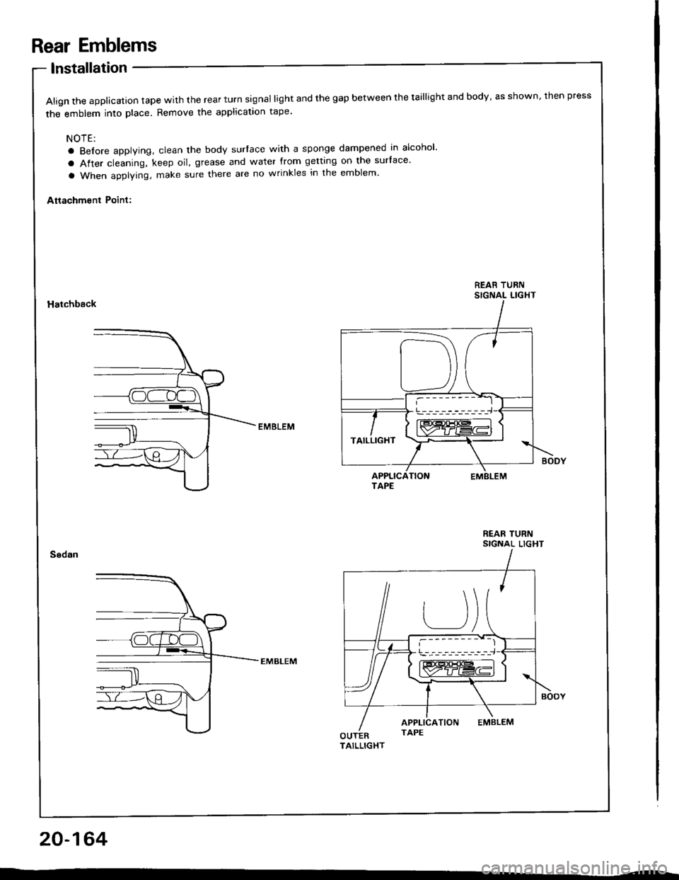
Rear Emblems
lnstallation
Align the applicalion tape with the rear turn signal light and the gap between the taillight and body, as shown, then press
the emblem into place. Remove the applicataon tape'
NOTE:
a Before applying, clean the body surlace with a sponge dampened in alcohol'
a After cleaning, keep oil, grease and water from getting on the surface'
a When applying, make sure there are no wrinkles in the emblem'
Attachment Point:
REAR TURNSIGNAL LIGHTHatchback
REAR TURNSIGNAL LIGHT
20-164
!---_-----------,-i-J
TAILLIGHT
Page 1047 of 1413
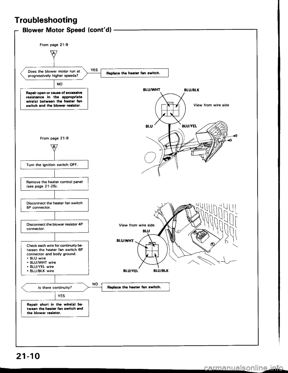
Does the blower motor run atprogressively higher speeds?Raplaca tho hollar fan rwitch.
Ropair opon or cau36 ol oxcoalivtrosbtanco in tho appaopaiatowire(3| b6twoon thg hostct lanswitch and tho blower todstor.
Turn the ignition switch OFF.
Remove the heater control panel(see page 21-25).
Check each wire for continuity be-tween the heater tan switch 6Pconnector and body ground.. BLU wire. BLUMHT wire. BLU/YEL wke. BLU/BLK wire
Raplaca tha haater lan awltch.
Bopair shon in the wir6{s} b€-lwo€n lho heatot lan switch rndth6 blowor ro3bto?.
From page 21-9
From page 21-9
View trom whe side
ilil
!\i
-l
I
View from wire side
BLU/U,HT
Troubleshooting
Blower Motor Speed (cont'd)
21-10
--
Page 1048 of 1413
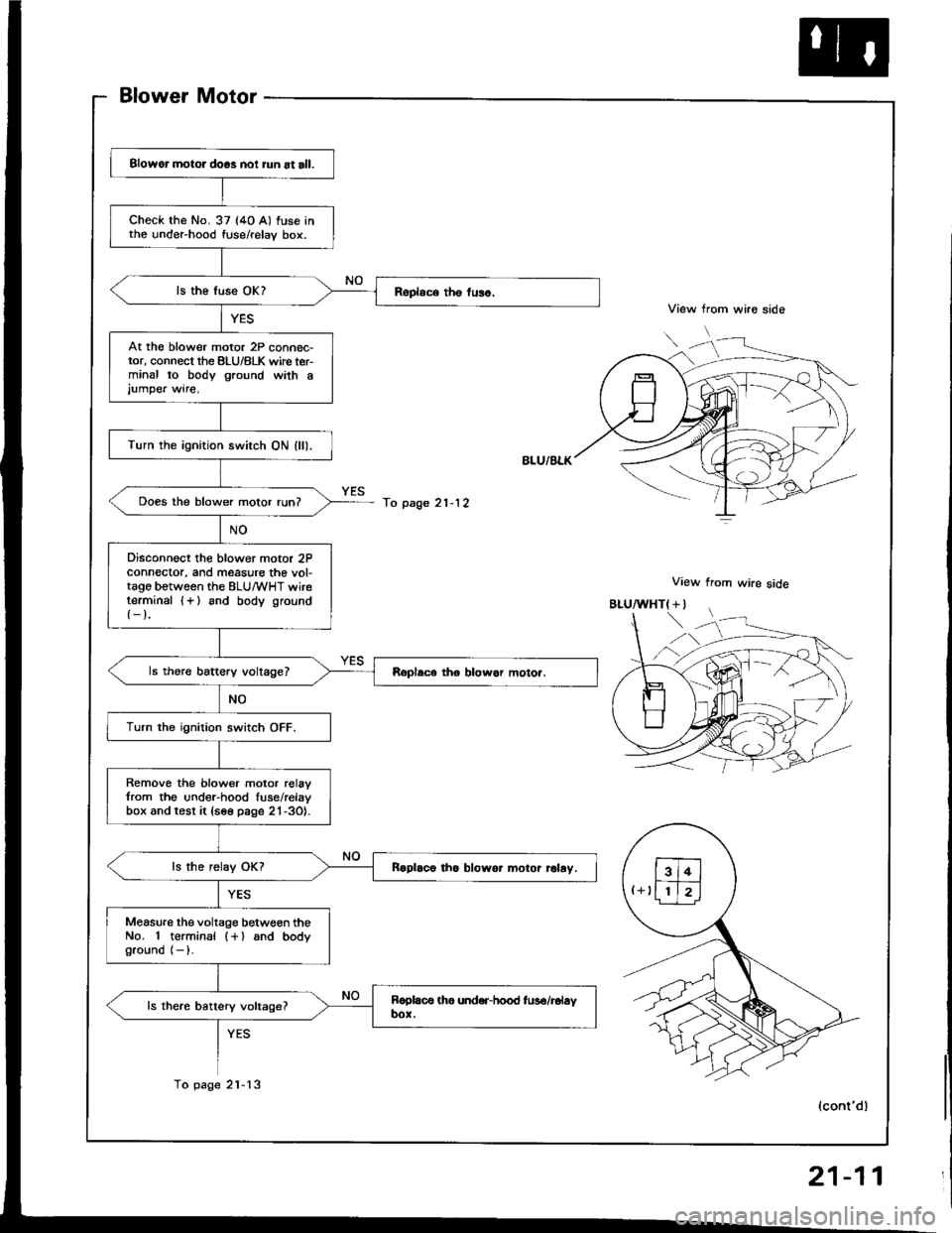
Blower Motor
View from wire side
View from wire side
Blowor motor doos noi iun at all.
check the No. 37 (4o A) fuse intho under-hood fuse/relay box.
At th€ blower motor 2P connec-tor, connect the BLU/8LK wirc ter-minal to body ground wath ajumpe. wire.
Turn the ignition switch ON (ll).
Does the blower motor run?
Disconnect the blower motor 2Pconnector, and measure the vol-tago between the ELU/wHT wireterminal {+} and body ground
{-}.
Turn the ignition switch OFF.
Remove the blower motor relavfrom the under-hood fuse/relavbox and test it {see page 21-3O}.
Roplaco tho blowor motor rolay.
Measure the voltage betwgen theNo. 1 terminal (+) and bodyground (- ).
To page 21-12
To page 2l-13
"uf"'\'
,)
(cont'dl
21-11
Page 1049 of 1413
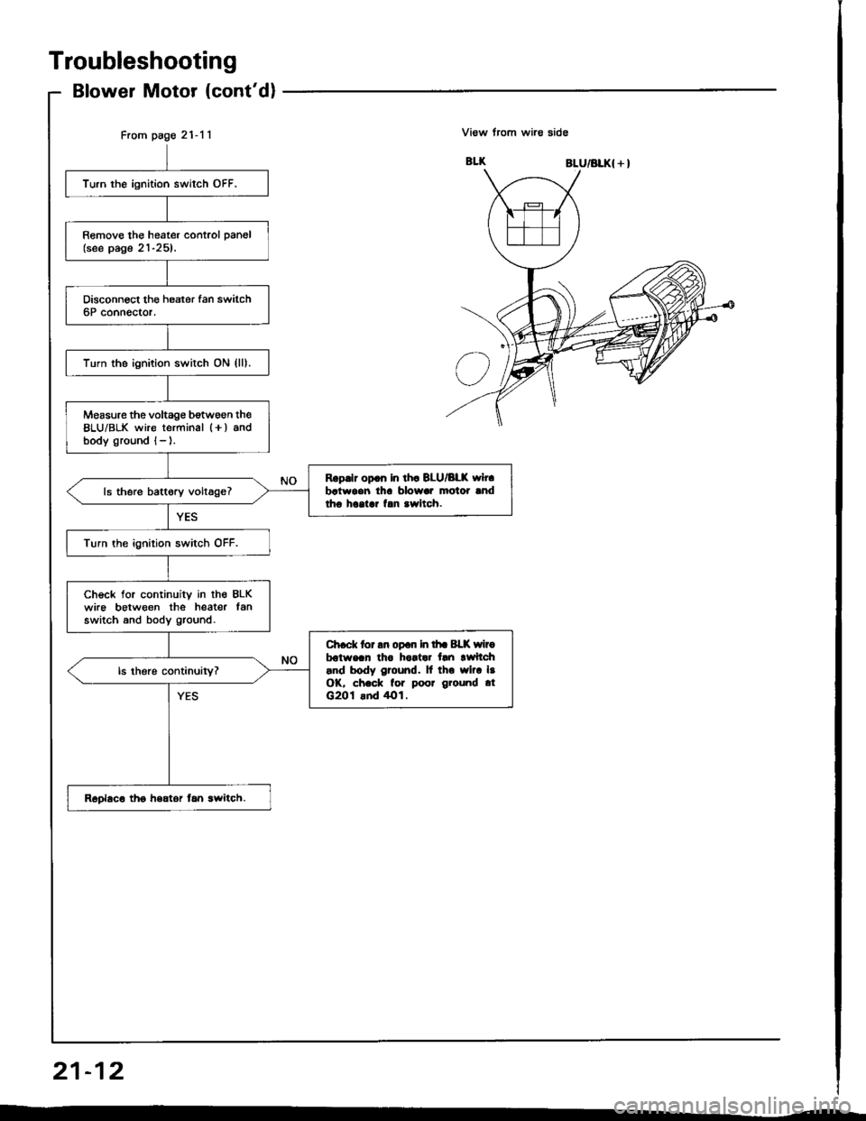
From page 21-11
Turn the ignition switch OFF.
Remove the heater control pan6l(see page 21-25).
Turn the ignition switch ON (lll.
Measure the voltage b€twsen the8LU/BLK wire terminal l+) andbody ground {- ).
Rgp.lr op.n In lh. BLU/BLK wh.batwoen lh! blowar motor lndtho hcolar f.n .wltch.ls there battory voltage?
Turn the ignition switch OFF.
Check tor continuity in lhe BLKwire between the heater lanswitch and body ground.
Ch.ck tor an opan in lhr Bl-K wirobdtwaan tho hortar tln lwftch.nd body ground. lf tho wlra l.OK, ch.ck for poor ground .tG201 .nd /rO1.
Roplaco tho hsator tan lwitch.
Troubleshooting
Blower Motor (cont'dl
View trom wire side
BLU/BLK{ + }
21-12
Page 1050 of 1413
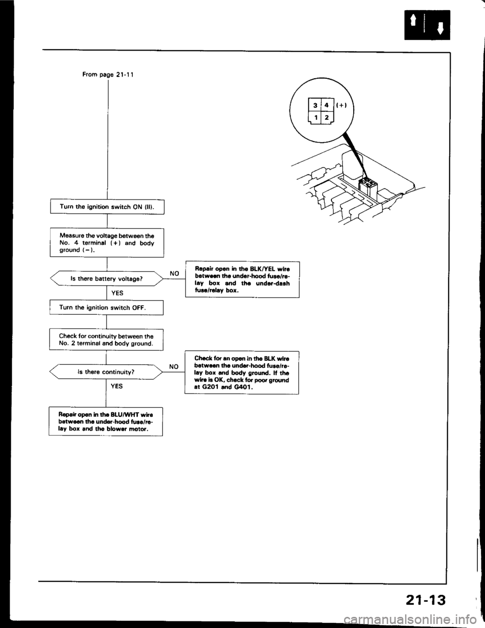
From page 21-11
Tu.n the ignition switch ON (ll).
Measure tho voltage botwoon thoNo. 4 torminal (+) 6nd bodvground (- l.
Ropair opan in tho BLK/YEL wir.batworn lha undor-hood fuaa/ra-hy box snd tho undor-dr.htur./rolay box.
ls there battery voltage?
Turn the ignirion switch OFF.
Check for continuity between theNo. 2 torminal and body ground.
Ch.d( to. !n oF|rn in th6 BLK wirobatwagn lho undar-hood luro/ra-lry box lnd body ground. ll th.wlre it OK. chock tor poo. groundat G2Ol lnd G/lol.
Rop.ir opon in th. BLU/WHT wlr.betweon tho undsr-hood lura/l.-lay box and tho blowor motoi.