connector HONDA INTEGRA 1994 4.G Workshop Manual
[x] Cancel search | Manufacturer: HONDA, Model Year: 1994, Model line: INTEGRA, Model: HONDA INTEGRA 1994 4.GPages: 1413, PDF Size: 37.94 MB
Page 1057 of 1413
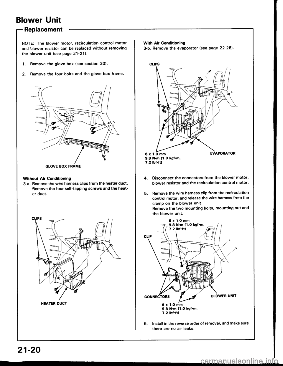
Blower Unit
Replacement
NOTE: The blower motor, recirculation control motor
and blower resistor can be replaced without lemoving
the blower unit (see page 2l-21).
1. Remove the glove box (see section 2O),
2. Remove the fou. bolts and the glove box frame.
Without Ail Conditioning
3-a. Remove the wire harness clips trom the heat€r duct.
Remove the Jour self-tapping screws 8nd the heat-
er duct.
GLOVE BOX FRAME
HEATER DUCT
With Air Conditioning
3-b. Remove the evaporator (see page 22-261.
CLIPS
6x I9.8 .ft 11.O kgt.m,7.2 tbt.ftl
4.
6.
Oisconnect the connectors from the blower motor,
blower resistor and the recirculation control motor.
Remove the wire harness clip from the recirculation
control motor, and release the wire harness from the
clamo on the blower unit.
Remove the two mounting bolts, mounting nut and
the blower unit,
6 x 1.0 mm
6 x 1.O mm9.8 N'm (1.0 kgf'm.7.2 tbt.ftl
lnstall in the reverse order of removal, and make sure
there are no air leaks.
9.8 .m (1.O kgl'm,7.2 lbf'ft}
21-20
--
Page 1062 of 1413
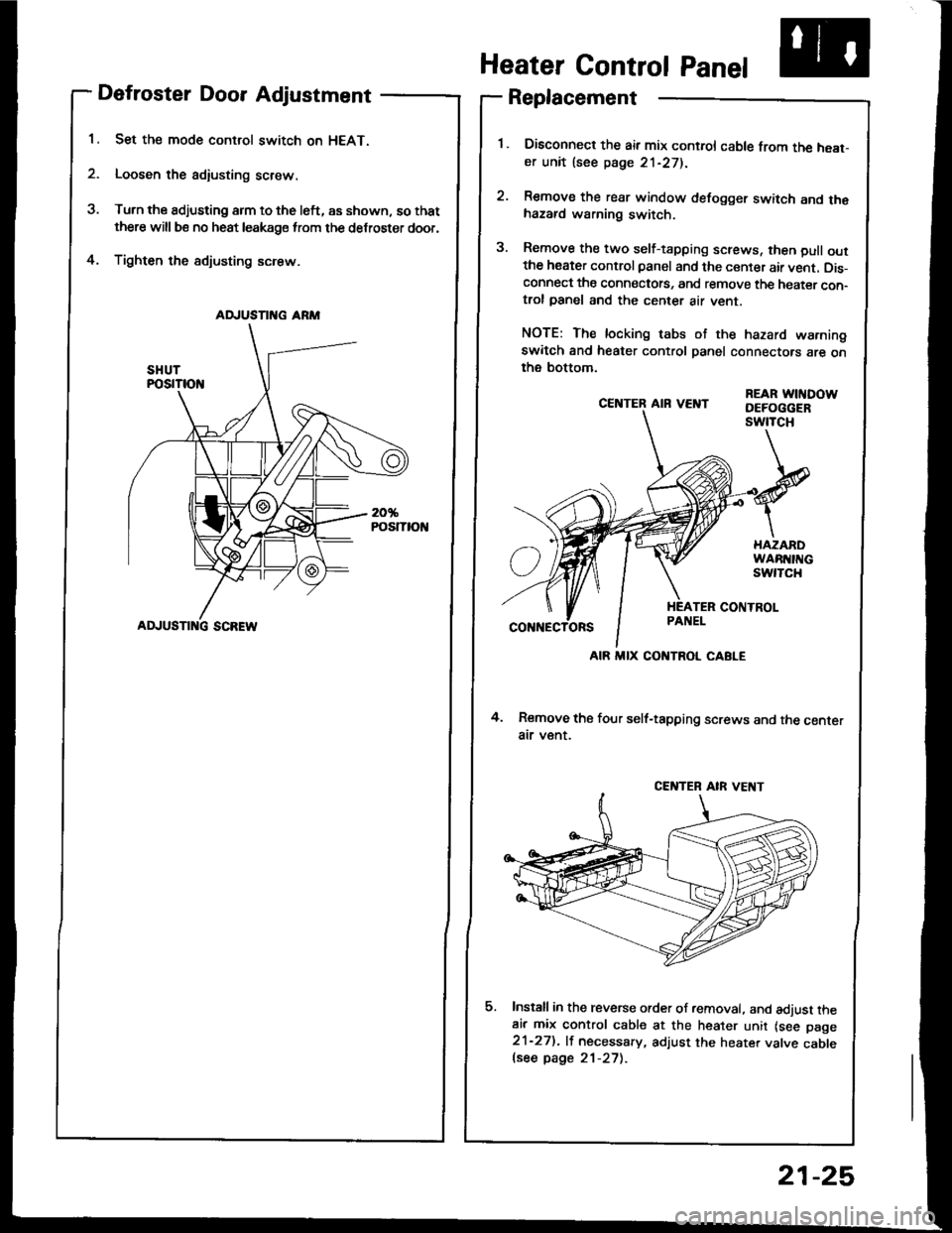
Defroster Door Adjustment
Set the mode control switch on HEAT.
Loosen the adiusting screw.
Turn the adjusting arm to the left, as shown, so that
there will be no heat leakage from the defroster door,
Tighten the sdjusting screw.4.
CE]TTER AIR VEI{T
4. Remove the four self-tapping screws and the centerair v€nt.
Install in the reverse order of removal. and adjust theair mix control cable at the heater unit lsee page21-27). lf necessary, adjust the heater valve cablelsee page 21-27).
REAR WITIDOWDEFOGGERswtTcH
Heater Control Panel
Replacement
Disconned the air mix control cable from the heat-er unit lsee page 21-271.
Remove the rear window defogger switch and thehazard warning switch.
Remove the two self-tapping screws, then pull outthe heater control panel and the center air vent. Dis-connect the connectots, and remove the heater con-trol panel and the center air vent.
NOTE: The locking tabs of the hazard warningswitch and heater control panel connectors are onthe bottom.
AD.'USTII{G ARM
ADJUSTI G SCREW
AIR MIX CONTROL CABLE
CENTEB AIR VE T
21-25
Page 1065 of 1413
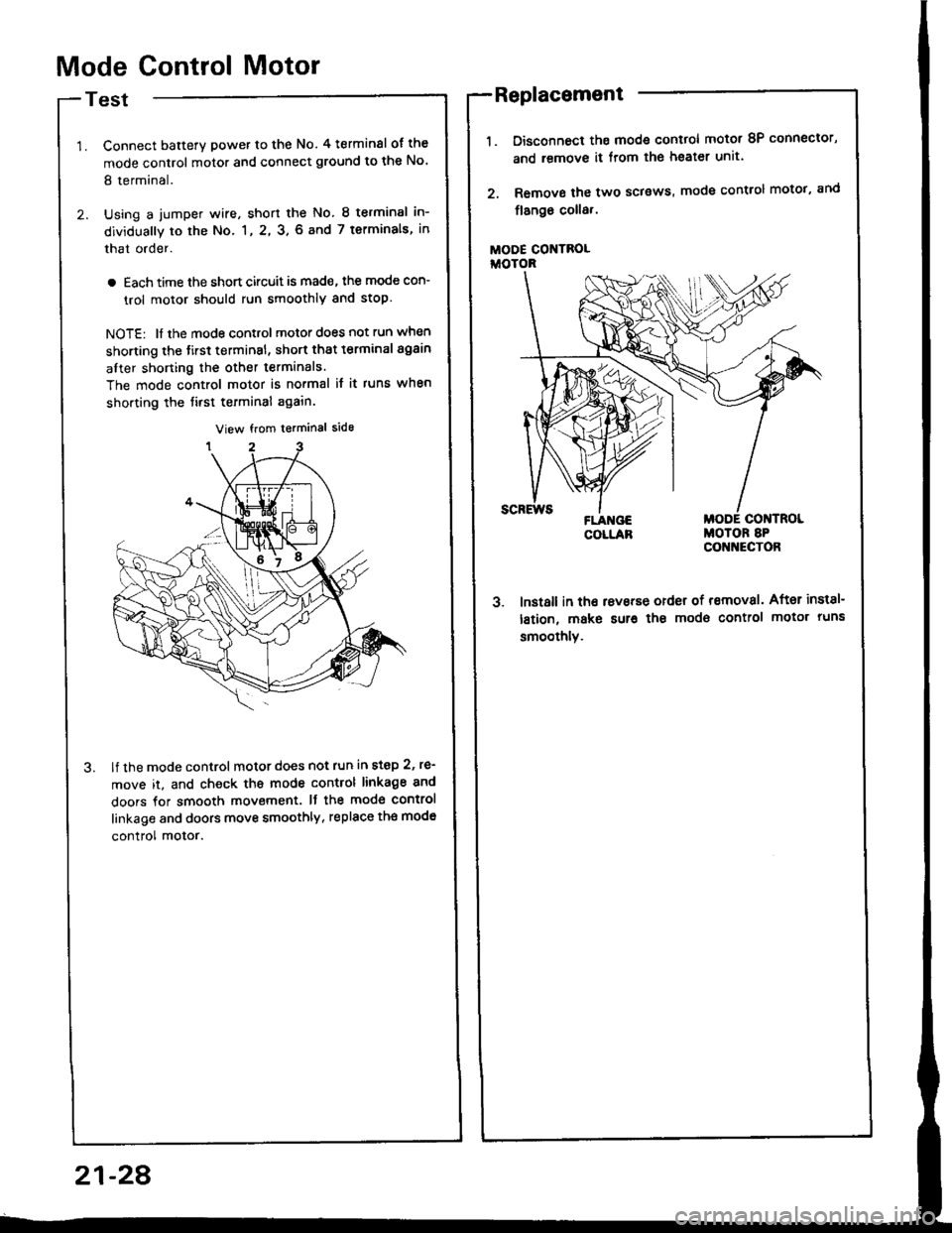
Mode Control Motor
Test
Connect batterY power to the No. 4 terminsl of the
mode control motor and connect ground to the No'
8 terminal.
Using a jumper wire, short the No. 8 terminsl in-
dividually to the No. 1, 2, 3. 6 and 7 terminals, in
that order.
a Each time the short circuit is mad€, the mode con-
trol motor should run smoothly and stop.
NOTE: ll the mode control motor does not run when
shorting the tirst terminsl, short that t€rminal again
after shorting the other terminals.
The mode control motor is no.mal it it runs when
shorting the tirst terminal again.
lf the mode control motor does not run in step 2, re'
move it, and check ths mode control linkage 8nd
doors for smooth movement. It the mod€ control
linkage and doors move smoothly, replace th€ mod€
control motor.
Disconnoct ths mode control motot 8P connector,
and remove it from lhe heater unit.
Remove the two sclsws, mode control motot, and
flango coll8,.
MODE CONTROLiioroR
3. lnst8ll in tho rsvsrse order of removal. After inst8l-
lstion, make sur€ the modo control motor runs
smoothlv.
Replacement
21-28
Page 1066 of 1413
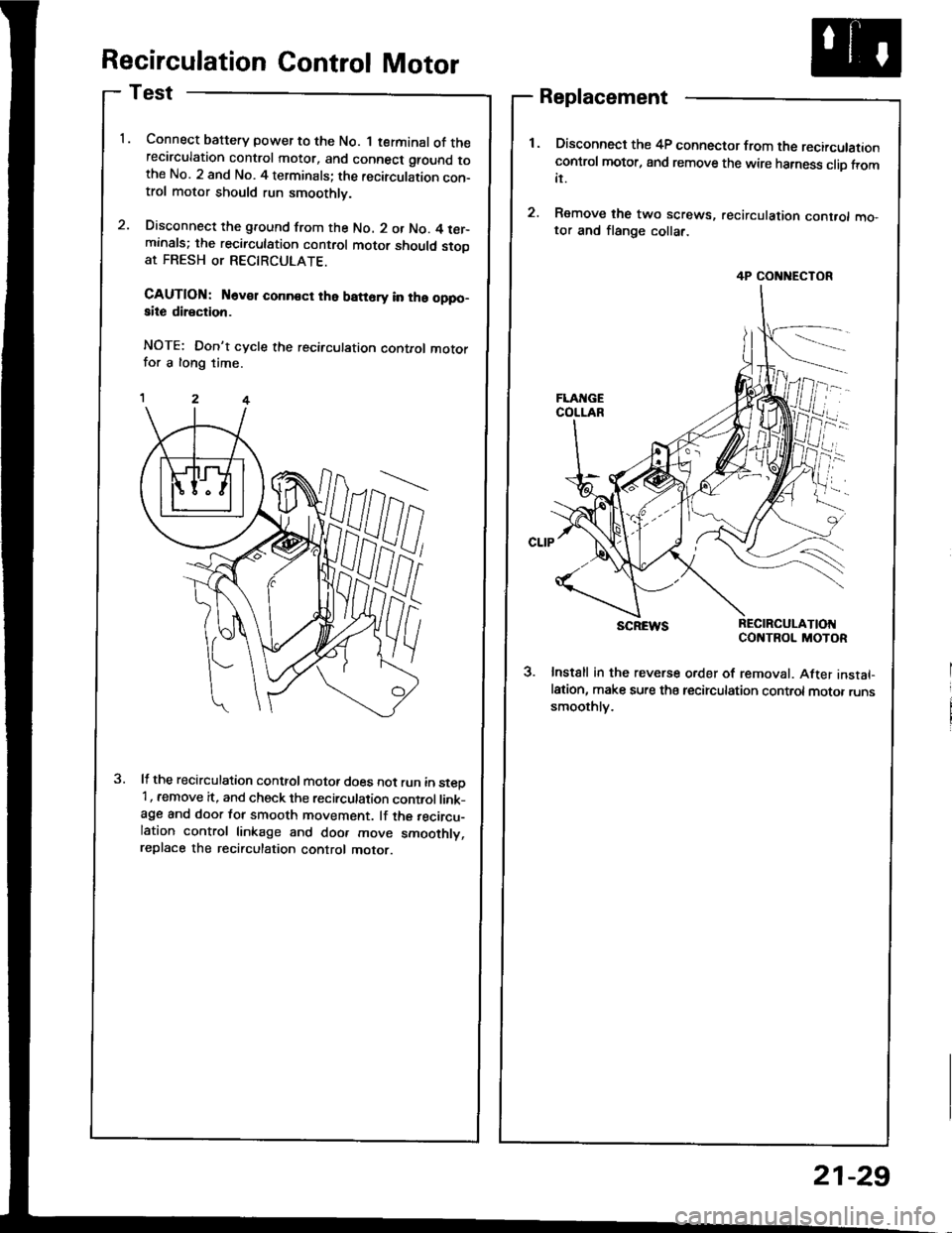
Recirculation Control Motor
Test
Connect baftery power to the No. 1 terminal of therecirculation control motor, and connect ground tothe No. 2 and No. 4 terminals; the recirculation con-trol motor should run smoothly.
Disconnect the ground from the No. 2 or No. 4 ter-minals; the recirculation control motor should stooat FRESH or RECTRCULATE.
CAUTION: N6v€r conn€ct the batt6ry in ths oppo-aite direction.
NOTE: Don't cycle the recirculation control motorfor a long time.
It the recirculation conttol motot does not run in steD'1, remove it, and check the recirculation control link-age and door for smooth movement. lf the recircu-lation control linkage and doo. move smoothly,replace the recirculation control motor.
Replacement
Disconnect the 4P connector from the recirculationcontrol motor, and remove the wire harness clio fromit.
Remove the two screws, recirculation cont.ol mo,tor and flange collar.
SCREWS REC|RCULAT|OIICONTROL MOTOR
3. Instsll in the reverse order of removal. After instal-lation, make sure tha tecirculation control motor runssmoothlv.
4P CONNECTOR
21-29
Page 1072 of 1413
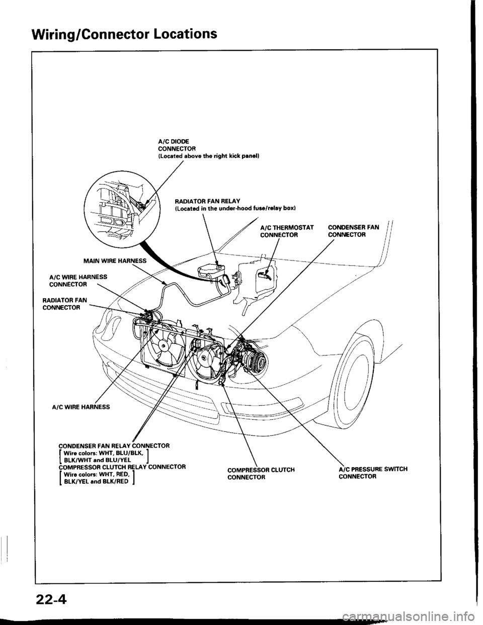
Wiring/Connector Locations
A/C DIODECONNECTOR(Loc.ted .bovo tho.ight kick p.n.ll
RADIA'OR FAN RELAY{Localed in the undel-hood fu3o/reltY box)
A/CTHERMOSTAT CONDENSERFANCONNECTOR CONNECTOR
MAIN WIRE HARNESS
A/C WIRE HARNESSCONNECTOR
RADIATOR FANCONNECTOR
A/C WIRE HARNESS
COMPRESSOR CLUTCHCONNECTORA/C PR€SSURE SWTTCHCONNECTOR
22-4
Page 1075 of 1413
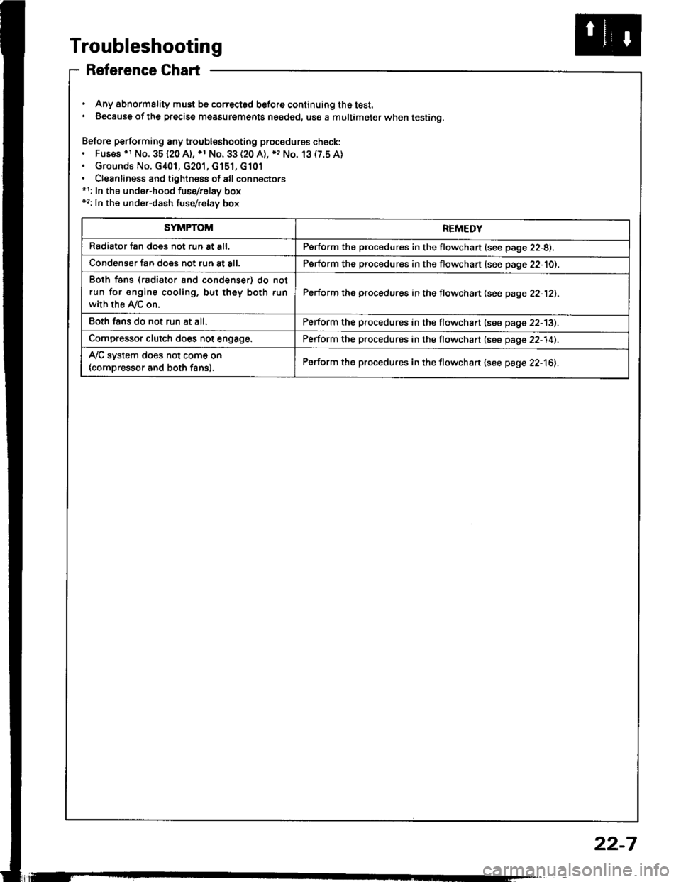
Troubleshooting
Reference Ghart
. Any abnormality must be correctsd before continuing the test.. Because of the precise measurgments needed, use a multimeter when testing.
Before performing any troubleshooting procedures check:. Fus€s .r No. 35120 A), *1 No. 33 (20 A), ), No. 13(7.5A). Grounds No. G401, G201, G'151, G101. Cleanliness and tightness of all connectors*1: In the under-hood fuse/relay box*2: In the under-dash fuse/relay box
SYMPTOMREMEDY
Radiator fan does not run 8t all.Perform the procedures in the flowchan (see page 22-8).
Condenser fan does not run at all.Perform the procedures in the flowchart (see page 22-10).
Both fans (radiator and condenser) do not
run for engine cooling, but they both run
with the Ay'C on.
Perform the procedures in the flowchan (see page 22-12).
Eoth fans do not run at all.Perform the procedures in the flowchart (see page 22-13).
Compressor clutch does not engage.Perform the procedures in the flowchart (see page 22-14).
Ay'C system does not come on
{compressor and both fans}.Perform the procedures in the flowchart (see page 22-16).
22-7
Page 1079 of 1413
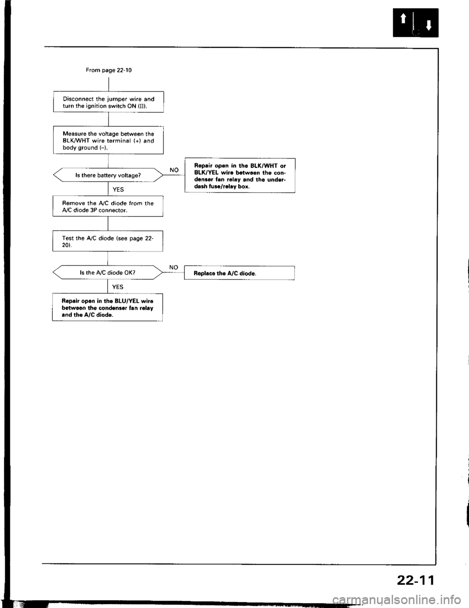
From page 22-10
Disconnect the iumper wire andturn the ignition switch ON (ll).
Measure the voltage between theBLK/WHT wire terminal (+) andbody ground (-).
Reptir open in tha BLK/WHT o.BLK/YEL wire betwoon tho con-den3o. f.n rel.y and tho unde.-dash tus6/rel.y box.
Remove the iay'C diode from theAy'C diode 3P connector.
ls the A,/C diode OK?
Reprir op6n in th. BLU/YEL wirebetwocn tho conden3er tsn reltv.nd tho A/C diod€.
22-11
Page 1081 of 1413
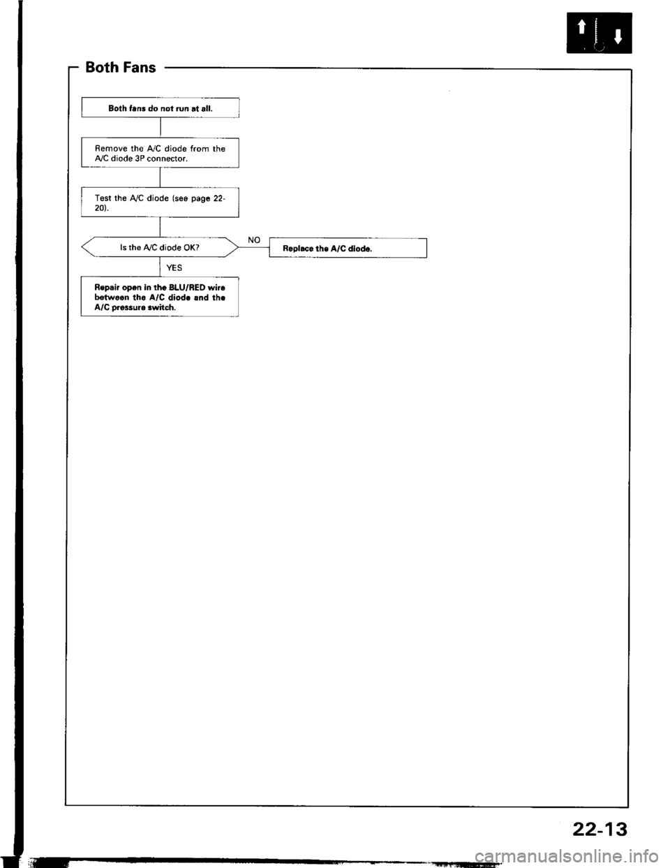
BothFans
Both tans do not run at all.
Remove the A,/C diode from theA,/C diode 3P connector.
ls the !y'C diode OK?
Rep.ir op€n in tho 8LU/RED wircbelwoen tho A/C diod. lnd th.A/C o.$sure lwitch.
22-13
Page 1084 of 1413
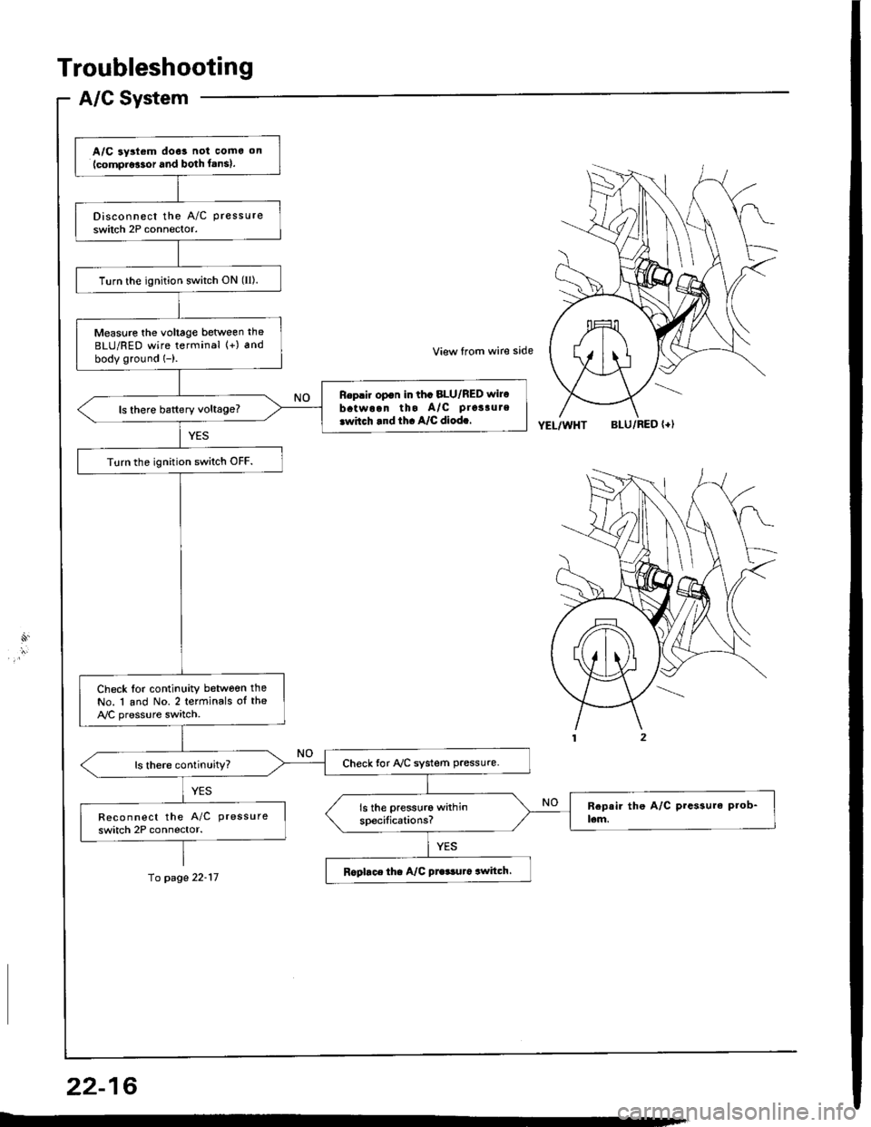
Troubleshooting
A/G System
10 page 22-17
A/C ay3t6m doe3 not como on(compro!3or and both f.ns).
Disconnect the A/C pressure
switch 2P connector.
Turn the ignition switch ON (II).
Measure the voltage beoveen the
BLU/RED wire terminal (+) and
bodv ground 1-).
Reprir opon in thc 8LU/RED wire
batwoan tho A/c prossute
rwitch rnd th. A/C diod..
Turn the ignition switch OFF.
Check lor continuity betwoen the
No. 1 and No. 2 terminals of the
A,/C pressure switch.
Check for NC system Pressure.
Reco n nect the A/C pressure
switch 2P connector.
Rophce tha A/C pre3!u.6 awitch.
View from wire side
YEL/WHTBLU/RED {+l
22-16
Page 1086 of 1413
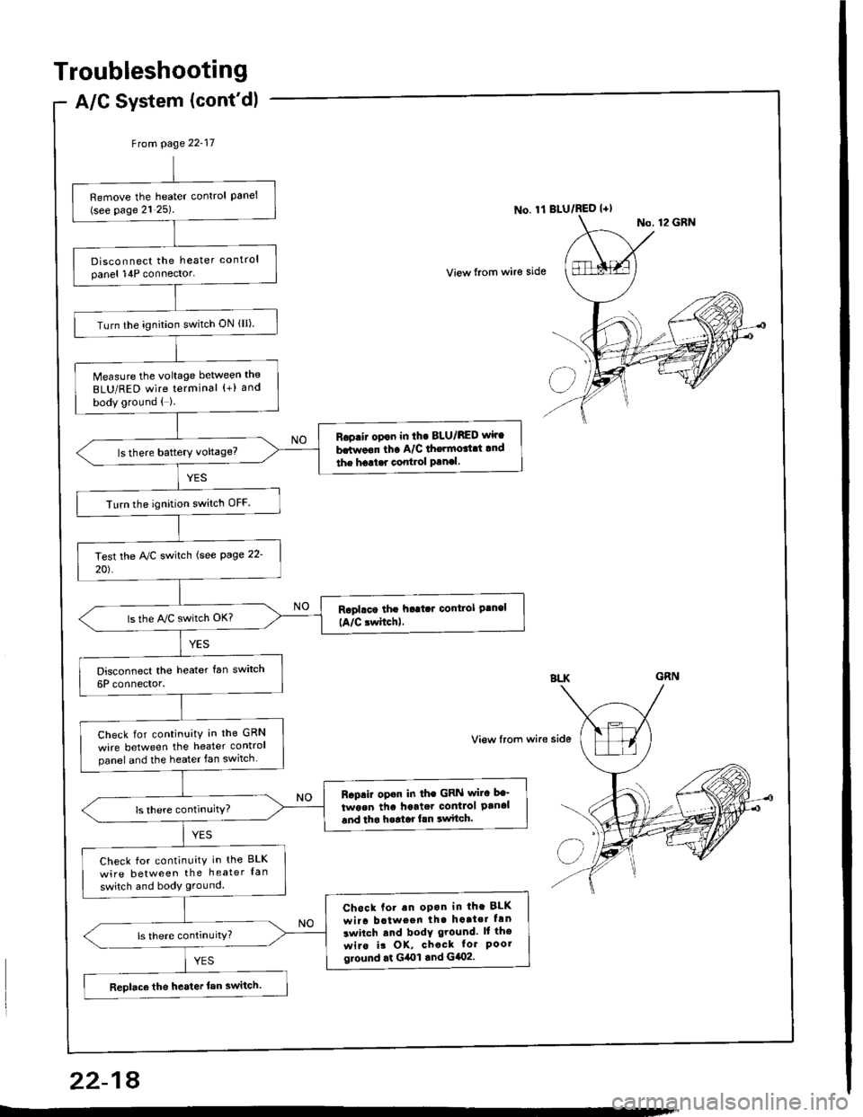
Troubleshooting
Remove the heater control Panel(see page 21 25)
Disconnect the heater controlpanel 14P connector'
Turn the ignition switch ON (lI).
Measure the voltage between the
BLU/RED wire terminal (+) and
body ground { }
Rop.i. opon in tho BLU/BED wir.
b.twoon tha A/C thermort.t lnd
the haat.r control Panal
Turn the ignition switch OFF.
ls the A/C switch OK?
Check for continuitY in the GRN
wire between the heater controlpanel and the heater fan switch
R.prir op.n in the GRN wiro be'
twoen thc hartet contlol Panaland tho h.rtor fln switch.
Check for continuity in the BLK
wire between the heater {an
switch and body ground.
Chock fol an opon in the BLK
wi.a b.tween th. hotte. hn
lwitch tnd bodY ground. ll tho
wiro it OK, chock for Poorg.ound .t G4ol .nd G402.
Replace the heater lan switch.
Frcm page 22'17
View lrom wire side
A/C System (cont'dl
No. 11 BLU/RED l+l
22-18