Block HONDA INTEGRA 1994 4.G Workshop Manual
[x] Cancel search | Manufacturer: HONDA, Model Year: 1994, Model line: INTEGRA, Model: HONDA INTEGRA 1994 4.GPages: 1413, PDF Size: 37.94 MB
Page 13 of 1413
![HONDA INTEGRA 1994 4.G Workshop Manual Lift and Support Points
Lift
Wh€n heavy 16ar compon€nts such aa susponsion, luel tank, spale tile and hatch ale to
il]iii6iliieigltt in the tuggage area bsfore hoisting. When substantial woight is HONDA INTEGRA 1994 4.G Workshop Manual Lift and Support Points
Lift
Wh€n heavy 16ar compon€nts such aa susponsion, luel tank, spale tile and hatch ale to
il]iii6iliieigltt in the tuggage area bsfore hoisting. When substantial woight is](/img/13/6067/w960_6067-12.png)
Lift and Support Points
Lift
Wh€n heavy 16ar compon€nts such aa susponsion, luel tank, spale tile and hatch ale to
il]iii6iliieigltt in the tuggage area bsfore hoisting. When substantial woight is lemoved from ths
b€ removod, plac6
l€ar ol th€ car, ths
cantor of gravity may chango and can cause the cal to tip folward on the hoist'
NOTE: Since each tire/wheel assembly weighs approximately 14 kg (30 lbs), placing the front wheels in trunk can assist
with the weight distribution.
1. Place the lift blocks as shown
2. Raise the hoist a lew inches (centimeters) and rock the car to be sure it is firmly supported.
3. Raise the hoist to full height and inspect lift points for solid support.
FRONT SUPPORT POINTLIFT BLOCKSBEAR SUPPORT POINT
1-9
Page 14 of 1413
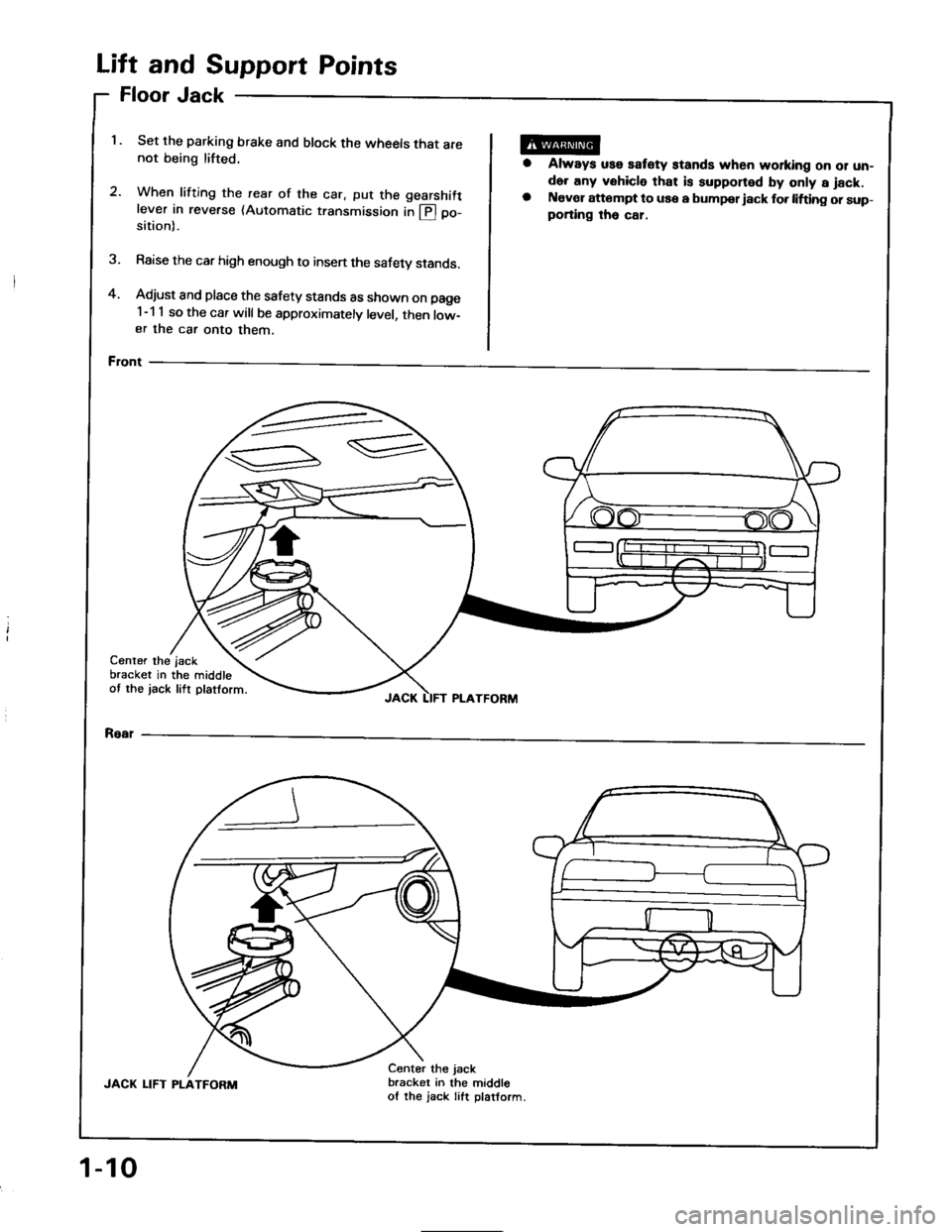
and Support Points
Jack
Set the parking brake and block the wheels that are
not being lifted.
2.When lifting the rearwhen tritrng the rear of the car, put the gearshift
lever in reverse (Automatic transmission in @ po-
of
sition).
Raise the car high enough to insen the safety stands.
Adjust and place the safety stands as shown on page
1-1 1 so the car will be approximately level, then low-
er the car onto them.
Front
oor
ft
FI
Li
4.
1.
a
Always uss satety stands when working oo 01 un-
der any vehicle that is supponed by only a jack.
Naver attompt to use a bumpor iack fo. lifting or sup-
porting tho car,
3.
Center the
bracket in
ot the jack
the middle
lift platform.
jsck
JACK LIFT PLATFORM
Rear
JACK LIFT PLATFORM
Center the jack
bracket in the middle
of the jack Iift platform.
1-10
Page 20 of 1413
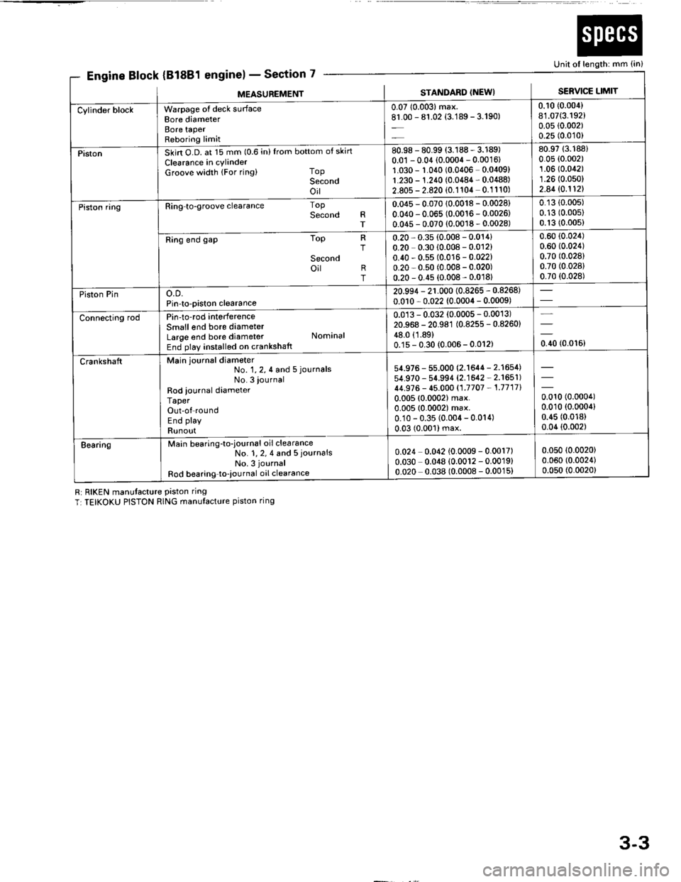
k (81881
Ri RIKEN manutacture Piston ring
T:TEIKOKU PISTON RING manufacture piston ring
7scti
Unit of length: mm {in}
Engine Block {Bl6E1 englnel - sectlon
MEASUNEMENTSTANDARD (NEWI SERVICE LIMIT
bottom of skirt
Top
Second
oil--
top
Second
'....=-
lop
Ring to-groove clearance
Ring end gap
o.D.
Pin-to-piston clearance
Pin-to-rod interference
Smallend bore diameter
Large end bore diameter
End play installed on crankshatt
Main journal diameter
Warpage ot deck sLrrface
Bore diameter
Bore taPer
Reboring limit
Skirt O.D. at 15 mm (0.6 in)Irom
Clearance in cylinder
Groove width (For ring)
R
T
;
T
No. 1, 2, 4 and 5 journals
No. 3 iournal
Rod iournal diameter
Taper
Out-of round
End play
Runout
Main bearing-to-iournal oil clearance
No. 1, 2, 4 and 5 journals
No. 3 journal
Rod bearing to-iournal oil clearance
Second
oit R
T
Nominal
0.0710.003)max.
81.00 - 81.02 {3.189 - 3.190)
0.10 (0.004)
81.07(3.192)
0.05 (0.002)
0.25 (0.010)
Cylinder block
80.98 - 80.99 (3.188 - 3.189)
0.01 - 0.04 (0.0004 - 0.0016)
1.030 - r.010 (0.0406 0.0409)
1.230 - 1.210 (0.0484 - 0.0488)
2.805 - 2.820 (0.1104 0.1110)
80.9713.188)
0.05 (0.002)
1.0610.042)
1.26 (0.050)
2.8410.112\
Piston
0.045 - 0.070 {0.0018 - 0.0028}
0.040 - 0.065 (0.0016 - 0.0026)
0.045 - 0.070 (0.0018 - 0.0028)
0.13 {0.00s)
0.13 (0.00s)
0.13 (0.005)
0.60 {0.024)
0.60 10.024)
0.70 (0.028)
0.70 (0.028)
0.70 (0.028)
Piston ring
0.20 - 0.35 (0.008 - 0.014)
0.20 0.30 (0.008 - 0.012)
0.40 - 0.5s (0.0 r6 - 0.022)
0.20 - 0.s0 (0.008 - 0.020)
0.20 - 0.45 (0.008 - 0.0181
20.994 - 21.000 (0.8265 - 0.8268)
0.0r0 - 0.022 (0.0004 - 0.0009)
rrston rln
0.013 - 0.032 (0.0005 - 0.0013)
20.968 - 20.981 (0.825s - 0.8260)
48.0 (1.89)
0.1s - 0.30 (0.006 - 0.012)
Connecting rod
54.976 - 55.000 (2.1644 - 2.1654)
54.970 - 54.994 (2.1642 - 2.1651)
44.S76 - 45.000 {1.7707 - 1.7717}
0.00510.0002) max.
0.005 (0.0002) max.
0.10 - 0.35 (0.004 - 0.014)
0.03 (0.001) max.
0.010 (0.0004)
0.010 (0.0004)
0.45 (0.018)
0.04 {0.002)
Crankshaft
0.024 0.042 {0.0009 - 0.0017)
0.030 0.048 {0.0012 - 0.0019}
0.020 0.038 (0.0008 - 0.0015)
0.05010.0020)
0.060 (0.0024)
0.050 (0.0020)
Bearing
3-3
Page 22 of 1413
![HONDA INTEGRA 1994 4.G Workshop Manual EBIk (818C1Section 7
Unit of length: mm (in)
ngrne ]ocK (ltluur englnel -
MEASUREMENTSTANDARD (NEWI SERVIC€ LIMIT
Cyiinder blockwarpage of deck surlace
Bore diameter
Bore taPer
Reboring limit
0.05 HONDA INTEGRA 1994 4.G Workshop Manual EBIk (818C1Section 7
Unit of length: mm (in)
ngrne ]ocK (ltluur englnel -
MEASUREMENTSTANDARD (NEWI SERVIC€ LIMIT
Cyiinder blockwarpage of deck surlace
Bore diameter
Bore taPer
Reboring limit
0.05](/img/13/6067/w960_6067-21.png)
EBIk (818C1Section 7
Unit of length: mm (in)
ngrne ]'ocK (ltluur englnel -
MEASUREMENTSTANDARD (NEWI SERVIC€ LIMIT
Cyiinder blockwarpage of deck surlace
Bore diameter
Bore taPer
Reboring limit
0.05 (0.002) max.
81.00 - 81.02 {3.189 - 3.190)
0.08 (0.003)
81.0713.192)
0.05 (0.002)
0.25 (0.010)
PistonSkin O.D. ar 15 mm (0.6 in) {rom bottom ot skirt
Clearance in cylinder
Groove width (For ring) ToP
Socond
oil
80.98 - 80.99 13.188 - 3.189)
0.0r - 0.04 {0.0004 - 0.0016}
1.030 - 1.0,r0 {0.0406 - 0.0409)
1.230 - 1.240 (0.0484 - 0.0488)
2.805 - 2.820 (0.1104 - 0.11101
80.97 (3.188)
0.05 (0.002)
1.060 (0.0417)
1.260 (0.0496)
2.840 (0.1118)
Piston ringRing-to-pistongrooveclearance Top
Second
0.045 - 0.070 {0.0018 - 0.0028}
0.010 - 0.065 (0.0016 - 0.0026)
0.13 (0.005)
0.13 (0.005)
Ring end gap I oP
Socond
oil
0.20 - 0.35 {0.008 - 0.014)
0.40 - 0,55 (0.016 - 0.022)
0.20 - 0.s0 {0.008 - 0.020}
0.60 (0.024)
0.70 (0.028)
0.7010.0281
rrston rtno.D.
Pin-to-piston clearance
20.994 - 21.000 (0.8265 - 0.8268)
0.010 - 0.022 {0.0004 - 0.0009)
0.017 - 0.035 (0.0007 - 0.0014)
20.964 - 20.997 (0.8254 - 0.8267)
€.0 (1.89)
0.15 - 0.30 (0.006 - 0.012)
Connecting rodPin to-rod int€rference
Small end bore diameter
Large end bore diameter Nominal
End play installed on crankshaft
crankshatt
No. 1,2,4 and 5 iournals
No. 3 journal
Rod iournal diameter
Taper
Out'ol round
End play
Runout
Msin journal diameter
54.976 - 55.000 (2.1644 - 2.16541
54.974 - 54.998 (2.'�|643 - 2.1553)
44.976 - 45.000 {1.7707 -'�I.7717)
0.005 {0.0002} max.
0.004 {0.0002) max.
0.10 - 0.35 {0.00{ - 0.014)
0.020 (0.0008) max.
-t-oou
lo.ooort
EearingMain bsaring-to-journal oil clearance
No. 1, 2, 4 and 5 journals
No 3 journal
Rod bearing-to-journal oil clearanc€
0.024 - 0.042 (0.0009 - 0.0017)
0.030 - 0.048 (0.0012 - 0.0019)
0.032 - 0.050 (0.0013 - 0.0020)
0.050 (0.0020)
0.060 {0.0024)
0.060 (0.0024)
3-5
Page 45 of 1413
Engine
Engine Removal/lnstallation ...''........ 5-1
Cylinder Head/Valve Train ..'............ 6-1
Engine Block ..........7-1
Engine Lubrication ......... 8-1
Intake Manifold/Exhaust System ...... 9-1
Cooling ....... 1O-1
Page 83 of 1413
!
1.
2.
Camshafts
Inspection
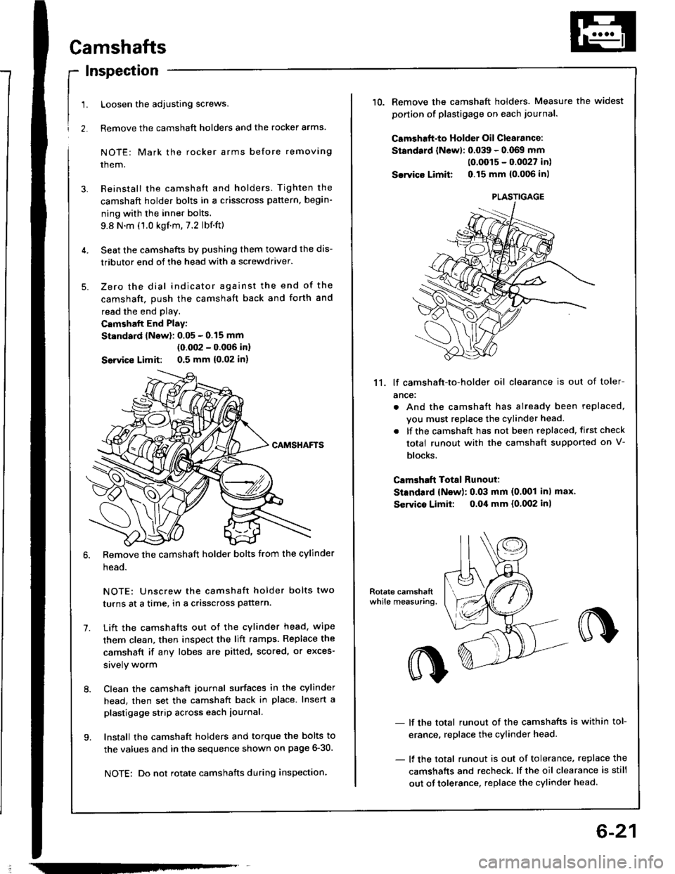
Loosen the adjusting screws.
Remove the camshaft holders and the rocker arms
NOTE: Mark the rocker arms before removing
them.
Reinstall the camshaft and holders. Tighten the
camshaft holder bolts in a crisscross pattern, begin-
ning with the inner bolts.
9.8 N.m (1.0 kgf.m,7.2 lbf.ft)
Seat the camshafts by pushing them toward the dis-
tributor end of the head with a screwdriver.
Zero the dial indicator against the end of the
camshaft. push the camshaft back and forth and
read the end play.
Camshalt End Play:
St.ndard lNow): 0.05 - 0.15 mm
(0.002 - 0.006 inl
Seivice Limit: 0.5 mm {0,02 in)
Remove the camshaft holder bolts from the cylinder
head.
NOTE: Unscrew the camshaft holder bolts two
turns at a time, in a crisscross pattern.
Lift the camshafts out ot the cylinder head. wipe
them clean, then inspect the lift ramps. Replace the
camshaft if any lobes are pitted, scored, or exces-
srvely worm
Clean the camshaft journal surfaces in the cylinder
head, then set the camshaft back in place. Insert a
plastigage strip across each iournal.
Install the camshaft holders and torque the bolts to
the values and in the sequence shown on page 6-30.
NOTE: Do not rotate camshafts during inspection.
-
6-21
10.Remove the camshaft holders. Measure the widest
ponion of plastigage on each journa..
Camshaft-to Holder Oil Clearance:
Standard lNewl: 0.039 - 0.069 mm(0.0015 - 0.0027 in)
Sarvico Limit 0.15 mm {0.006 inl
11. lf camshaft-to-holder oil clearance is out of toler
ance:
. And the camshaft has already been replaced,
vou must replace the cylinder head.
. lf the camshaft has not been replaced, first check
total runout with the camshaft supported on V-
blocks.
Clmshaft Total Runout:
StEndard {New): 0.03 mm (0.001 inl max'
Servico Limit: o.Oil mm {0.002 inl
- lf the total runout of the camshafts is within tol-
erance, replace the cylinder head.
- lf the total runout is out of tolerance, replace the
camshafts and recheck. lf the oil clearance is still
out of tolerance. replace the cylinder head.
PLASTIGAGE
Page 90 of 1413
t
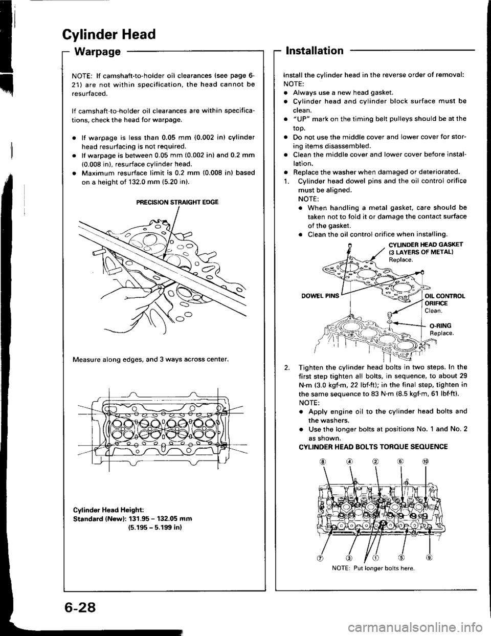
Gylinder Head
Installation
Installthe cylinder head in the reverse order of removal:
NOTE:
. Always use a new head gasket.
. Cylinder head and cylinder block surface must be
ctean.
. "UP" mark on the timing belt pulleys should be at the
top.
. Do not use the middle cover and lower cover for stor-
ing items disassembled.
. Clean the middle cover and lower cover before instal-
lation.
. Replace the washer when damaged or deteriorated.'1. Cylinder head dowel pins and the oil control orifice
must be aligned,
NOTE:
. When handling a metal gasket, care should be
taken not to told it or damage the contact surface
of the gasket.
. Clean the oil control orifice when installing.
CYLINDER HEAD GASKET
{3 LAYERS OF METALIReplace.
OOWEL PINSorl coNtnolORIFICEClean.
O.RINGReplace.
Tighten the cylinder head bolts in two steps. In the
Jirst step tighten all bolts, in sequence, to about 29
N.m {3.0 kgf.m, 22 lbl.ltJ; in the final step, tighten in
the same sequence to 83 N.m (8.5 kgf.m, 61 lbf'ft).
NOTE:
. Apply engine oil to the cylinder head bolts and
the washers.
. Use the longer bolts at positions No. 1 and No. 2
as shown.
CYLINDER HEAD BOLTS TOROUE SEOUENCE
@o@@@
NOTE: lf camshaft-to-holder oil clearances (see page 6-
21) are not within specitication, the head cannot be
resurfaced.
lf camshaft'to-holder oil clearances are within specifica-
tions, check the head for warpage.
lf warpage is less than 0.05 mm (0.002 in) cylinder
head resurtacing is not required.
lf warpage is between 0.05 mm (0.002 in) and 0.2 mm
(0.008 in), resurface cylinder head.
Maximum resurface limit is 0.2 mm (0.008 in) based
on a height of 132.0 mm (5.20 in).
Measure along edges, and 3 ways across center.
Cylinder Hoad Height:
Standard (New): 131.95 - 132.05 mm
{5.195 - 5.191t in}
PRECISION STRAIGHT EOGE
Put longer bolts here.
Page 127 of 1413
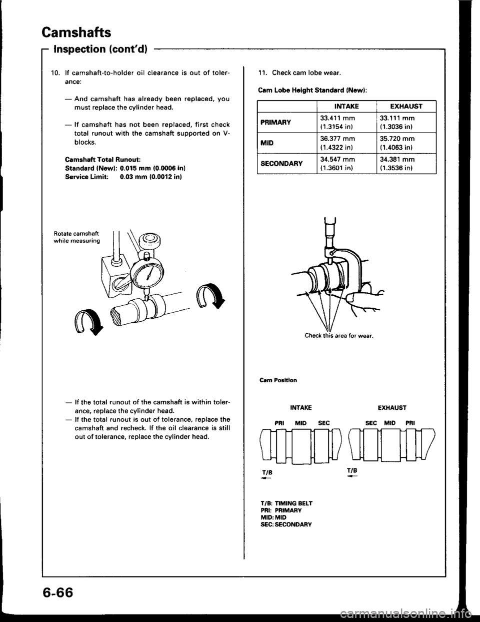
Gamshafts
Inspection (cont'd)
10, lf camshaft-to-holder oil clearance is out of loler-
ance:
- And camshaft has already been replaced, you
must replace the cylinder head.
- lf camshaft has not been replaced, first check
total runout with the camshaft supported on V-
blocks.
Camehaft Total Runout:
Sisndard (New): 0.015 mm (0.0006 inl
Service Limit: 0.03 mm (0.0012 in)
Rotat€ camshsftwhile measuring
- lf the total runout of the camshaft is within toler-
ance, replace the cylinder head.- lf the total runout is out of tolerance, r€Dlace the
camshaft and recheck. lf the oil clearance is still
out of tolerance. replace the cylinder head.
6-66
IiITAKEEXHAUST
PRIMARY33.i{'l1 mm
(1.3154 inl
33.111 mm(1.3036 in)
MID36.377 mm
l't.4322 inl
35.720 mm
(1.4063 inl
SECONDARY34.547 mm(1.3601 in)
34.381 mm(1.3536 in)
11. Check cam lobe wear.
Clm Lobs Hcight Standard (N.w):
Check this are6 tor wsar.
Crm Porition
INTAKE
MtosEc
CXHAUST
SEC MID PRI
fTt-]--Tt-Tt-l
\ll il il|/
tt ttlLIL__H___}{-}U
ftBftB
T/B: nMING BELTPRI: PRIMAFYMID: MIDSEC: SECONDARY
Page 141 of 1413
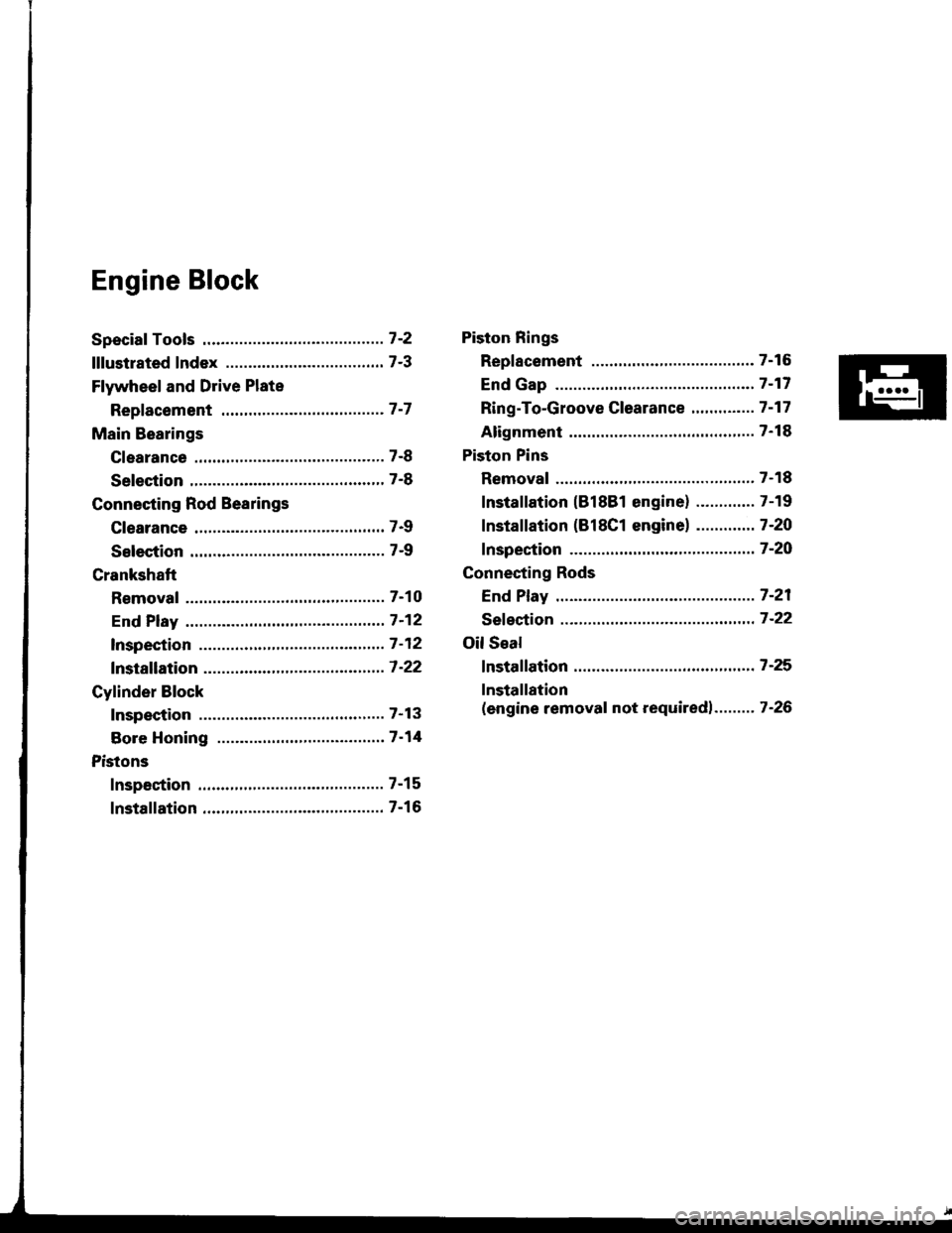
Engine Block
Speciaf Tools .............7'2
lllustrated Index ................................... 7-3
Flywheel and Drive Plate
Repfacement .........7-7
Main Bearings
Clearance ,.............. 7-8
Selection ................ 7-8
Connecting Rod Bearings
Clearance ............... 7-9
Selection ................ 7-9
Crankshaft
Removal .................7-10
End Play .................7-12
lnspection ........,,,.,,7-12
fnstallation .............7'22
Cylinder Block
Inspeetion ..............7-13
Bore Honing .....,.,,.7'14
Pistons
Inspaction ..............7-15
Installation .............7-16
Piston Rings
Replacement .........7-16
End Gap .................7-17
Ring-To-Groove C|earance,,,,.,,,...... 7 -17
Alignment ..............7-18
Piston Pins
Removal ........,........7-18
Installation (818B1 engine) ............. 7-19
fnstaffation (818C1 enginel ............. 7-20
fnspection ..............7-2O
Connecting Rods
End Play .................7-21
Sefeetion ..........,,,,,,7-22
Oil Seal
fnstaffation .............7-25
Installation
(engine removal not requiredl.. .......7-26
Page 143 of 1413
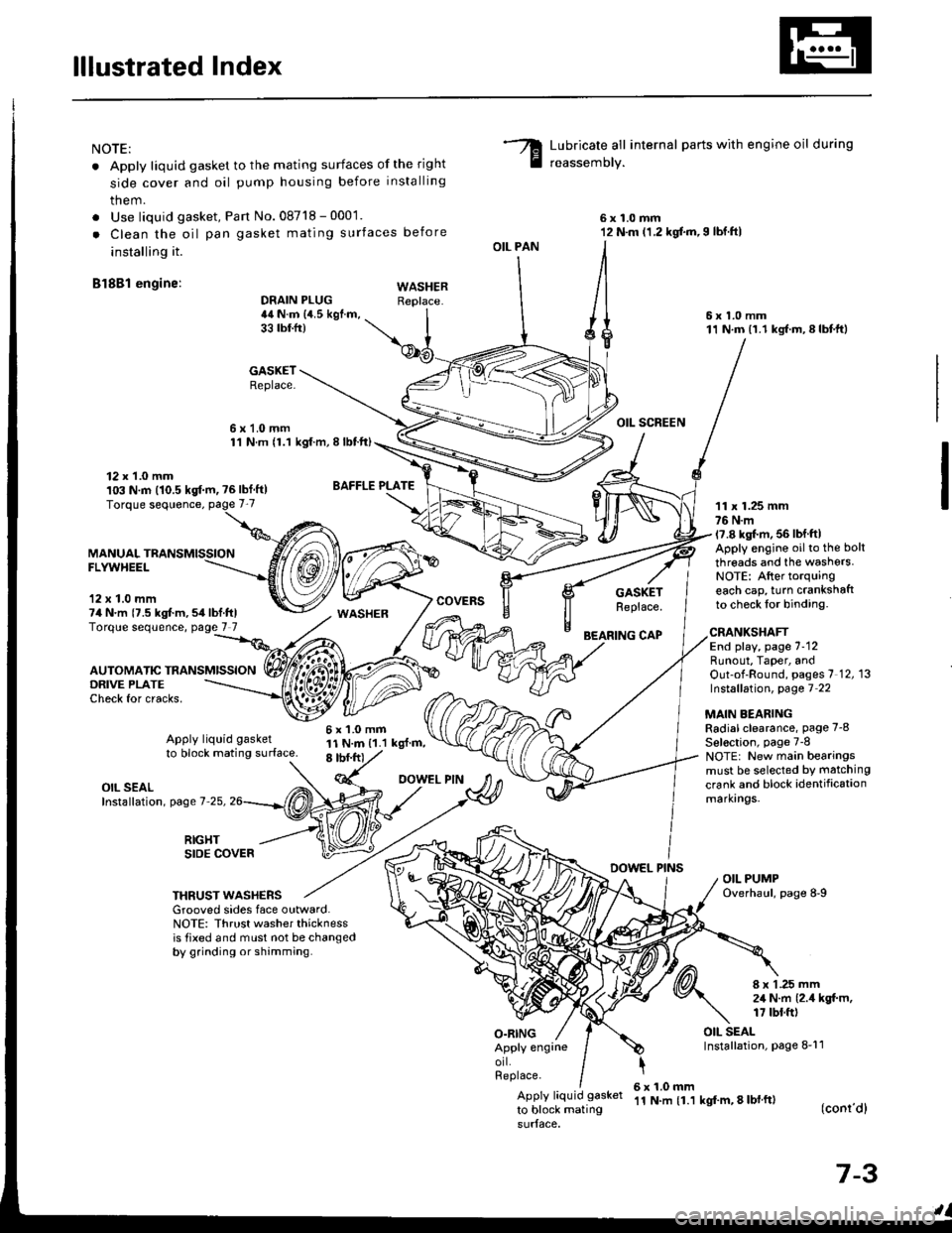
lllustrated Index
NOTE:
. Apply liquid gasket to the mating surfaces of the right
side cover and oil pump housing before installing
them.
. Use liquid gasket, Pan No.08718 - 0001.
. Clean the oil pan gasket mating surfaces before
installing it.
Bl8Bl engine: wAsHEF
Lubricate all internal parts with engine oil during
reassemory.
6x1.0mm12 N.m (1.2 kgf.m,I lbf.ftl
6x1.0mm11 N.m (1.1 kgf.m,8lbtft)
OIL SCREEN
11 x 1.25 mm76 N.m17.8 kgl.m, 56 lbf ftlApply engine oilto the bolt
threads and the washers.NOTE: After torquingeach cap, turn crankshaftto check lor binding.
DRAIN PLUG44 N.m {4.5 kgf.m,33 tbtfr)
GASKETReplace.
6x1.0mm1'l N.m {1.1 kgt.m, I lbtft)
OIL PAN
O.RING
GASKETReplace.
BEARING CAP
12 x 1.0 mm103 N.m (10.5 kgf.m, ?6lbf ft)
MANUALFLYWHEEL
'12 x 1.0 mm74 N.m {7.5 kgt m,54lbf.ftlTorque sequence, page 7 7
DRIVE PLATECheck for cracks,
AUTOMATIC TRANSMISSION
WASHER
6x1.0mm11 N.m {1.1 kgl.m,8 tbf.frt
CRANKSHAFTEnd play, page 7-12Runout, Taper, andOut-of-Round, pages 7 12, 13Instsllation, page 7 22
MAIN BEARINGRadial clearance, page 7-8
Sel€ction, page 7-8NOTE: New main bearingsmust be selected by matching
crank and block identificationmarkrngs.
Apply liquid gasket
to block mating surface.
OIL SEALInstallation, page 7-25,
RIGHTSIDE COVERDOWEL PINSOIL PUMPOverhaul, page 8-9THRUST WASHERSGrooved sides face outward.NOTE: Thrust washer thicknessis tixed and must not be changedby grinding or shamming.
8 x 1 .25 mm2,1 N.m {2.4 kgt m,17 tbt.ft)
OIL SEALInstallation, page 8-11Apply engrneorl.Replace.
Apply liquid gasket
to block mating
6x1.0mm'11 N.m {1.1 kgf'm, 8 lbl ft)(conr'dl
7-3