roll HONDA INTEGRA 1994 4.G Workshop Manual
[x] Cancel search | Manufacturer: HONDA, Model Year: 1994, Model line: INTEGRA, Model: HONDA INTEGRA 1994 4.GPages: 1413, PDF Size: 37.94 MB
Page 31 of 1413
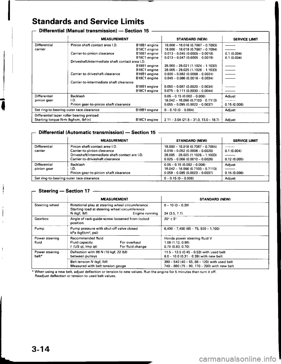
Standards and Service Limits
Differential (Manual transmissionlSection 15
Differential (Automatic transmissionlSection 15
Steering - Section 17
' When using a new belt, adjust detlection or tension to new values. Run the engine lor 5 minutes then turn it off.Readiust detlection or tension to used belt values.
M€ASUREMENTSTANDARD INEW) SERVICE LIMIT
DifferentialPinion shaft contact area LD. 81881 engine818C1 engineCarrier'to-pinion clearance 81881 engineB18C t engineDriveshafvintermediate shaft contact area LD.81881 engine818C1 engineCarrier to driveshaft clearance 81881 engineBlSC'l engineCarrier-to-intermediate shatt clearanceB188l engine818C1 engine
18.000 - 18.016 (0.7087 - 0.7093)18.000 18.018 (0.7087 - 0.7094)0.0r3 0.045 (0.0005 - 0.0018)0.0'13 - 0.047 (0.0005 0.0019)
28.000 - 28.021 \1.1024-1.1032128.005 - 28.025 (1.1026 1.'1033)0.020 - 0.062 (0.0008 0.0024)0.045 , 0.086 {0.0018 - 0.0034)
0.050 - 0.087 (0.0020 0.0034)0.075 - 0.111 (0.0030 - 0.0044)
o. t aron,0.1 {0.006}
Differentialprnron gearEacklasht. D.Pinion geaFto-pinion shaft clearance
0.05 0.15 (0.002 0.006)'18.042 - 18.066 (0.7103 0.7113)0.055 - 0.095 (0.0022 0.0037)
Adjust
0.15 {0.006)
Sel ring-to-bearing outer race clearance 81881 engin€0 - 0.10 (0 0.004)Adjust
Differential taper roller bearing preloadStarting torque N.m {kgfcm, lbf.in) Bl8Cl engine2.1r - 3.04 {21.5 - 3 r.0, 13.0- 18.7)Adjust
MEASUREMENTSTANDARO INEWISERVICE LIM]T
Difterentialcarfl€rPinion shatt contact area l.D.Carrier-to-oinion clearanceDriveshafvintermediate shaft contact are l.D.Carrier-to-driveshatt clearance
18.000 - 18.018 {0.7087 - 0.7094)0.016 - 0.052 {0.0006 - 0.0020)28.00s 28.025 {1.1026 - 1.1033)0.025 - 0.066 (0.0010 - 0.0026)
0.1 {0.004)
0.12 (0.005)
Differentialprnron gearBacklasht.D.Pinion gear-to-pinion shaft clearance
0.05 - 0.15 (0.002 - 0.006)18.042 - 18.066 (0.7r03 - 0.7113)0.059 - 0.095 (0.0023 - 0.0037)
Adjust
0.15 (0.006)
Set ring-to-bearing outer race clearance0 - 0.r5 (0 - 0.006)Adjust
MEASUREMENTSTANDARD INEWI
Steering wheelRotational play at steering wheel circumferenceStaning losd at steering wheel circumferenceN {kgf, lbfl Engine running
0 - 10 {0 - 0.39)
34 \3.5,7.71
GearboxAngle of rack-guide-screw loosened from lockedposition20" i 5'
PurnpPump pressure with shut-off valve closedkPa (kgtlcm,, psi)6,400 7.400 165 75. 920 - 1. r00)
Power steeringtluidRecommended fluidFluid capacity For overhaulf (US qt, lmp q0 For fluid change
Honda power steering fluid V1.06 (1.12,0.98)
0.79 (0.83,0.70)
Power steeringbelt*Deflection with 98 N (1okgt,22lhfl
between pulleys11.5- 13.5 (0.45 0.53)with used belt8.0 - 10.010.31 0.39)with new belt
Belt tension N lkgf, lbl)Measured with belt tension gauge390 - 540 (40 - 55, 88 - 120) with used belt740 880175 90. 170 200) with new belt
Page 34 of 1413
![HONDA INTEGRA 1994 4.G Workshop Manual Design Specifications
]TEMMETRICENGLISHNOIES
: vENSTONSOveralllength 3 DOOR
4 DOOR
Ov€rallWidth
Overall Height 3 DOOR
4 DOOR
Wheelbase 3 DOOR
4 DOOR
Track F/R
Ground Clearance
Seating Capacity
4.38 HONDA INTEGRA 1994 4.G Workshop Manual Design Specifications
]TEMMETRICENGLISHNOIES
: vENSTONSOveralllength 3 DOOR
4 DOOR
Ov€rallWidth
Overall Height 3 DOOR
4 DOOR
Wheelbase 3 DOOR
4 DOOR
Track F/R
Ground Clearance
Seating Capacity
4.38](/img/13/6067/w960_6067-33.png)
Design Specifications
]TEMMETRICENGLISHNOIES
:' vENSTONSOveralllength 3 DOOR
4 DOOR
Ov€rallWidth
Overall Height 3 DOOR
4 DOOR
Wheelbase 3 DOOR
4 DOOR
Track F/R
Ground Clearance
Seating Capacity
4.380 mm
4.525 mm
'1,710 mm
1,335 mm
1,370 mm
2,570 mm
2,620 mm
't,475/1,470 mm
150 mm
Four (3 DOOR)
172.1in
178.1 in
67.3 in
52.6 in
101.2 in
103.1 in
5|8.1/57.9 in
Five (4 DOOR)
,rerght (usA)cross V€hicle Weight Rating {GVWR)3,680lbs
'le,ght {CANADA)Gross Vehicls Weight Rating {GVWR)1,670 kg
:\GINEType81881 engine
818C1 engine
Cylinder Arrangement
Bore and Stroke
Displacement
Compression Ratio
81881
818C1
81881
B18C I
81881
B 18C1
81881
818C1
engrne
engane
engrne
engine
engine
engine
engine
engine
L!brication Systom
OilPump Displacement
Wster Pump Displacement
FuelRequired
81881
B18C 1
81881
B 18C1
91881
engrne
engrne
engine
engine
engine
818C1 engine
Water-cooled, 4-stroke DOHC
gasoline engine
Watercooled, 4-stroke DOHC
VTEC gasoline engine
Inline 4-cylinder, transverse
81.0 x 89.0 mm
81.0 x 87.2 mm
1,834 cm3 (mf )
1,797 cm3 (m{)
3.19 x 3.50 in
3.19 x 3.43 in
112 cu-in
110 cu-in
9.2:1
10.0 : 1
Eelt driven, OOHC 4 valve per cylinder
Belt driven, DOHC VTEC
4 valve per cylinder
Forced and wet sump, trochoid pump
50, {53 US qt, 44 lmp qt)/minute'l
71 f {75 US qt, 62 lmp qt)/minute"
140 f (148 US qt, 123 lmp qt)/minute*!
140 f (148 US qt. 123 lmp qt)/minute*'
UNLEADED gasoline with 86 Pump
Octane Numb€r or higher
Premium UNLEADED gasoline wilh
91 Pump Octane Number or higher
STARTERTypo
NormalOutput
NominalVoltage
Hour Rating
Direction of Rotation
Weight
Gear reduction
1.4 kW
12V
30 seconds
Clockwise as viewed lrom g6ar end
3.7 k9 | 8.3lbs
CLUTCHClutch Type
Clutch Facing Area
M/TSingle plate dry, diaphragm spring
Torq!e converter
203 cm'� I 31 sq-in
TRANSMISSIONTransmission Type M/T
Primary Reduction
Synchronized 5-speed forward, 1 reverse
Electronically controlled
4-speed automatic. 1 rcverse
Diract 1 : 1
'1: At 6,000 engine
'2: At 7,600 engine
rpm
rpm
(cont'd)
3-17
Page 48 of 1413
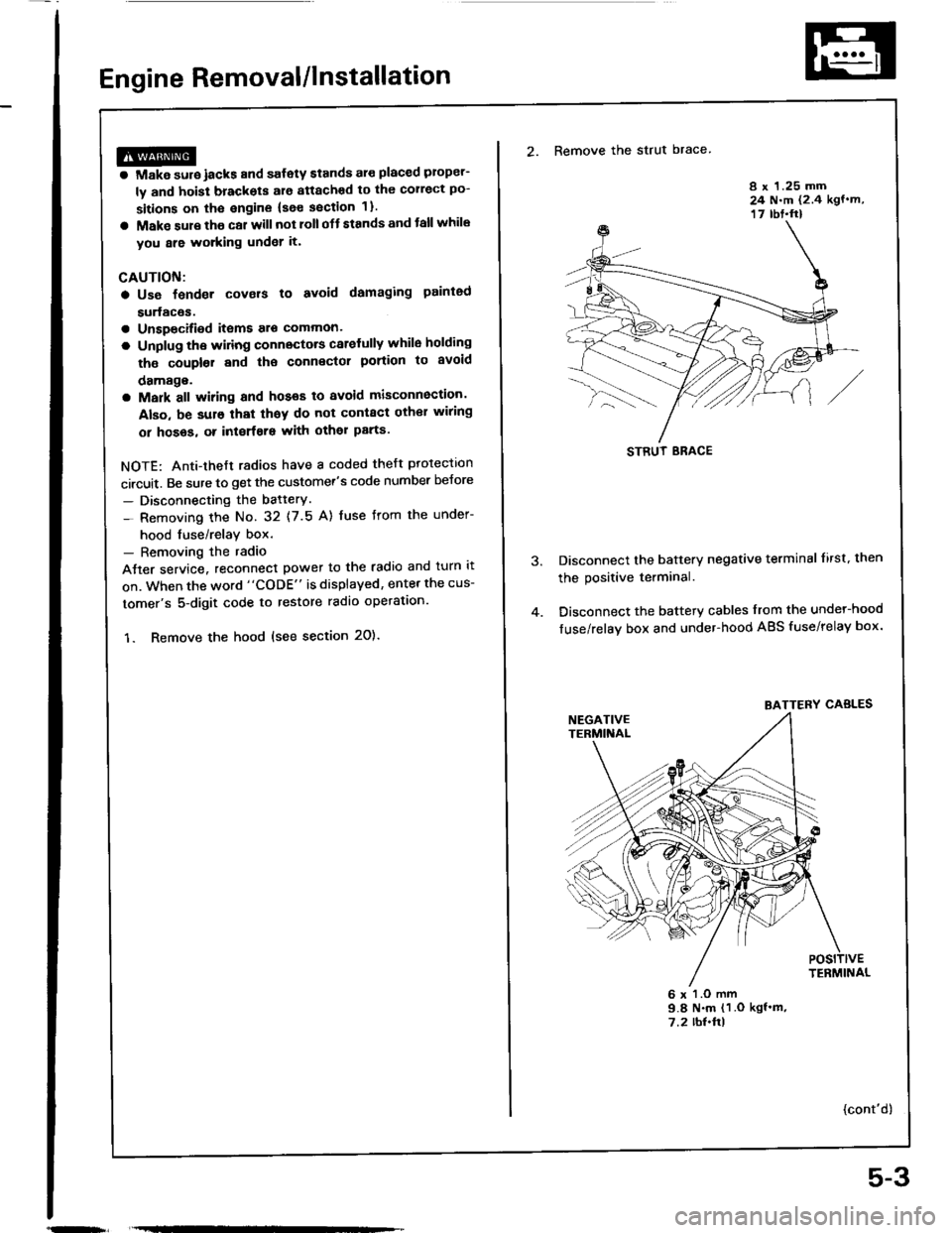
Engine Removal/lnstallation
@a Make sure jacks and safety stands aro placed ploper-
ly and hoisl brackots arg attachod to the correct po-
sitions on tho engine (se€ ssction 1).
a Mak€ sure tho car willnot roll off stands and tallwhile
you are wotking under it'
CAUTION:
a Use fendet covals to avoid damaging painted
sudaces.
r Unspecified itsms alo common
a Unplug tho widng connectots carefully while holding
the couplor and tha connector portion to avoid
oamage.
a Mark all wiring and hoses to avoid misconnection.
Also, be sulo that thsy do not contact other wiring
or hoses, or interfere with oth€l parts.
NOTE: Anti-theft radios have a coded theft ptotection
circuit. Be sure to get the customer's code number beJore
- Disconnecting the batterY.
- Removing the No. 32 (7.5 A) fuse from the under-
hood tuse/relay box.- Removing the radio
Atter service, reconnect power to the radio and turn it
on. When the word "CODE" is displayed, enter the cus-
tomer's 5-digit code to restore radio operataon.
1. Remove the hood (see section 2O).
2. Remove the strut brace
8 x 1.25 mm24 N.m (2.4 kgf.m,17 rbt.ft)
Disconnect the battery negative terminal lirst. then
the positive terminal.
Disconnect the battery cables from the undel-hood
fuse/relay box and under-hood ABS fuse/relay box.
6 x l.O mm9.8 N.m (1 .O kgf'm,7.2 rbl.ftl
{cont'd)
STRUT ERACE
BATTERY CABLES
5-3
Page 54 of 1413
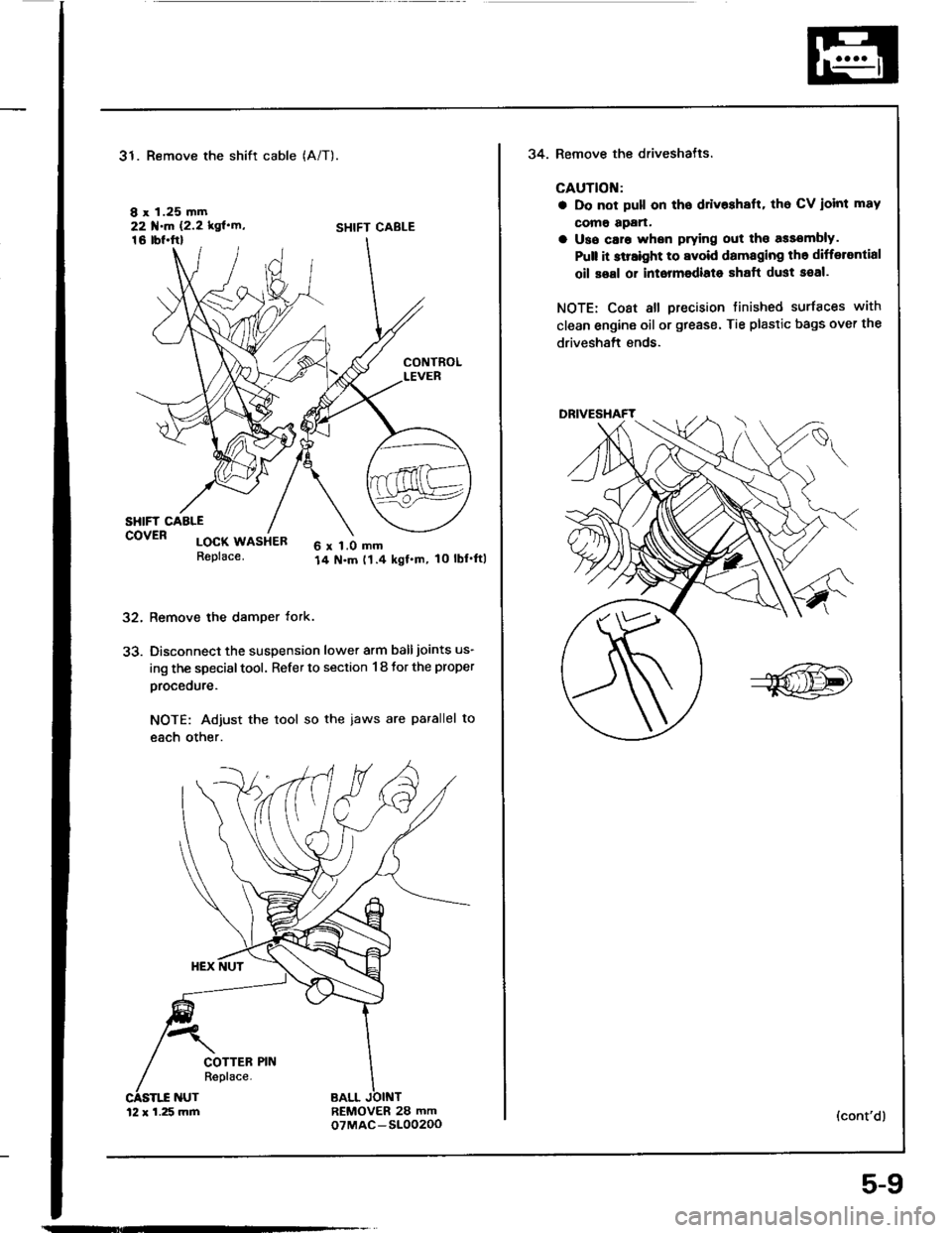
31. Remove the shift cable
I x 1.25 mm22 f.m 12.2 kgl'rn'16 tbl.ftl
(A/T).
SHIFT CABLE
32.
33.
CONTROLLEVER
SHIFT CAALEcovER locx usiea6 x 1.0 mm14 N.m t1.4 kgf.m, 10 lbl'ftlReplace.
Remove the damper tork.
Disconnect the suspension lower arm balljoints us-
ing the special tool. Refer to section 1 8 tor the proper
procedure.
NOTE: Adjust the tool so the iaws are parallel to
each other.
REMOVER 28 mmoTMAC-S10020012 x 1.25 mm
5-9
34. Remove the driveshatls.
CAUTION:
a Do not pull on tho ddv$halt, tho CV ioint mav
como apan.
a Uso caro whsn prying out tho assombly.
Pult it slraight to avoid damaging th6 differantial
oil soal or intormodiato shaft dust seal.
NOTE: Coat all precision tinished surfaces with
clean engine oil or grease. Tie plastic bags over the
driveshaft ends.
(cont'd)
Page 217 of 1413
c4't9
234578e nc
5t6 | -
aALUfYELYEL'
c423
c431lwlthcruit€coniroll
| 'lrl
lslnl
fitr G-Fil------lo ln/Hr/68n Ilo lciN,r/vHr Il-IcRY------l
c44il
riTLF-Iffi14l51617l
lO lGRt/8LU ITitfgruffir-----lktlBrKr--I o lYcL/Gnir Ilao laLx./YEL II "] IYEUBL( Iktlterwirr ---
c431(wlthout
crui!acontrol)
-tttI
t3
l6'TwHr/cnN ----'l
1ol cRN^vHr ----l
c439
rfltrrn
I'VCT,1
lETWrr;eo---ffrlwHr. --
l3l8rK II t lBLx,REo It5 |I 6 GRN/BLX If?-TFEpcFN --
c432
ffi
c444
ffir
trtr]
I6TLK^//Hr -l
L ' l!!g!!r llo lsLkrFED I|;TBLU'BLi l]l
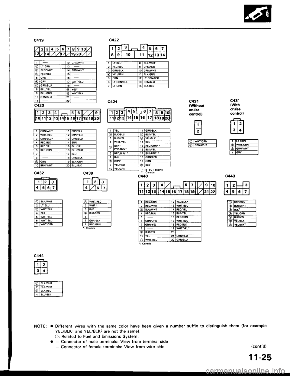
NOTE: a Ditterent wires with the same color have been given a number suttix to distinguish them (fot example
YEL/BLKr and YEL/BLK, are not the samel.
O: Related to Fuel and Emissions System.
a - Connector of male terminals: View from terminal side- Connector of female terminals: View from wire side(cont'd)
11-25
12313
5BLU/YEL6
a1a
20
YEL/BLK'2Ht/aluiEO/YIL15516't7
aBL&"/EL20YEL
Page 233 of 1413
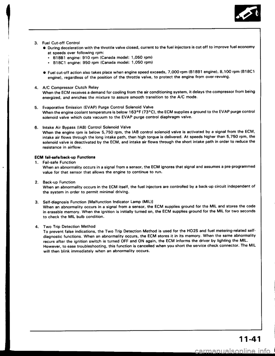
3. Fuel Cut-oft Control
a During deceleration with the throttle valve closed, current to the {uel injectors is cut otJ to improve fuel economy
at speeds over tollowing rpm:
. 8188l engine: 91O tpm (Canada model: 1,O50 rpm)
. 818C1 engine: 95O tpm (Canada model: l,O5O rpm)
a Fuel cut-olf action also takes place when engine speed exceeds, 7,O0O rpm {81 8B1 engine), 8,1O0 rpm (B 18Cl
engine), regardless oI the position of the throttle valve, to protect the engine from ovet-revving.
A/C Compressor Clutch Relay
When the ECM receives a domand for cooling trom the air conditioning system, it del8ys the compressor from being
enetgized, and enriches the mixture to assure smooth transition to the A/C mode.
Evaporative Emission (EVAP) Purge Control Solenoid Valve
When the engine coolant tempersture is below 163oF {73"C), the ECM supplies a ground to the EVAP pu.ge control
solenoid valve which cuts vacuum to the EVAP purge control diaphragm valve.
Intake Air Bypsss (lAB) Control Sol€noid Valve
When the engine rpm is below 5,750 rpm, the IAB control solenoid valve is activated by a signal from the ECM,
intske air flows through the long intake path, then high torque is delivered. At spaeds highe. than 5,750 rpm, the
solenoid valve is deactivated by the ECM, and intake air flows through the short intake path in order to reduce the
resistance in airflow.
ECM fail-safe/bEck-up Functions
1. Fail-sate Function
When an abnormality occurs in a signal from a sensor, the ECM ignores that signal and assumes a pre-progtammed
value tor that sensor that allows the engine to continue to run.
Back-uD Function
When an abnormalitv occurs in the ECM itself, the fuel iniectors are controlled by a back-up citcuit independent of
the system in order to permit minimal driving.
Self-diagnosis Function IMaltunction Indicator Lamp {MlL)1
Wh6n an abnormality occurs in a signal from a sensor, the ECM supplies ground for the MIL and stores the code
in erasable memory. When the ignition is initially turned on, the ECM supplies ground tor the MIL tor two seconds
to check the MIL bulb condition.
Two Trio Detection Method
To prevent tals€ indications, th€ Two Trip Dstection Method is used for the HO2S and fuel metering-related self-
diagnostic tunctions. When an abnormslity occurs, the ECM stores it in its memo.y. Wh€n the ssme sbnormality
recurs alter the ignition switch is turned OFF and ON ag8in, the ECM informs the driver by lighting the MlL.
However, to ease troubleshooting, this function is canc€ll€d when you short the service check connector. The MIL
will then blink immedistelv when an abnormality occurs.
4.
6.
2
4.
11-41
Page 268 of 1413
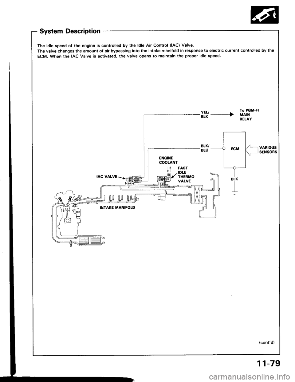
System Description
The idle speed ot lhe engine is controlled by the ldle Air Control {lAC) Valve.
The valve changes the amount ot air bypassing into the intake manifold in response to electric current controlled by the
ECM. When the IAC Valve is activated, the valve opens to maintain the proper idle speed.
#l' ----rTo FGM-FIMAINRELAY
VARIOUSSENSORS
IAC VALVE
FASTIDLETHERMOVALVE
INTAKE MAI{IFOLD
(cont'd)
BLK
r
11-79
Page 269 of 1413
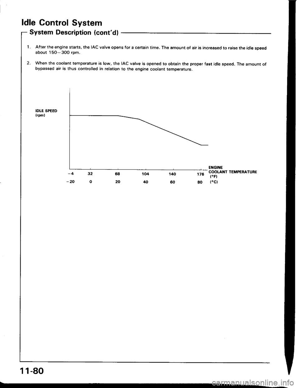
ldle Control System
System Description (cont'd)
1 . Atter the engine slarts. the IAC valve opens for a censin time, The amount ot air is increased to raise the idle soeedabout 15O-3OO rom.
2. When the coolant temperature is low, the IAC valve is opened to obtain the proper fast idle speed. The amount ofbypassed air is thus controlled in relation to the engine coolant temperature.
IDI-E SPEEDlrpm)
176
80
ENGINECOOLANT TEMPERATURE
t"Fl(oct
11-80
Page 283 of 1413
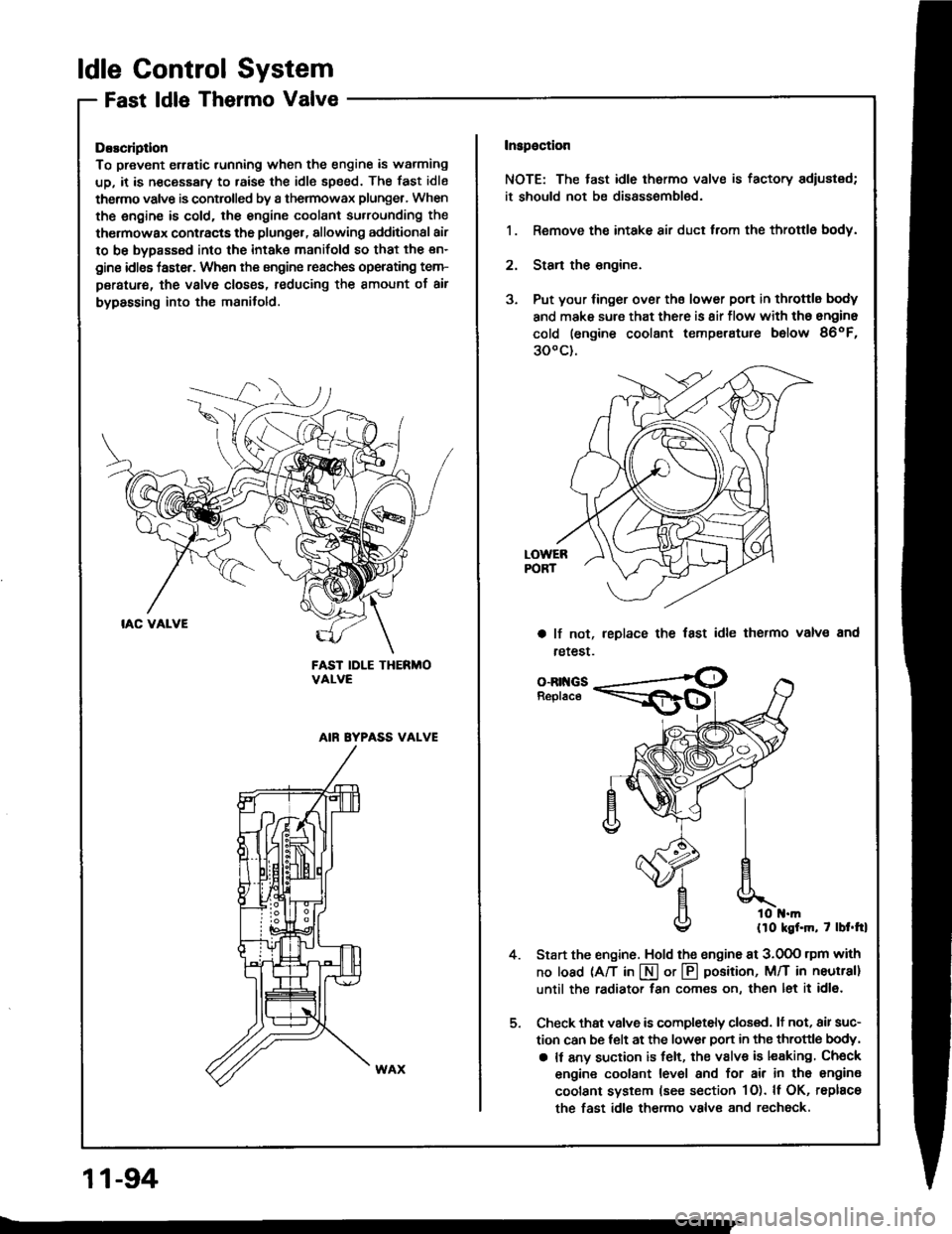
ldle Control System
Fast ldle Thermo Valve
DEscliptlon
To prevent erratic running when the engine is warming
up, it is n€cessary to raise the idle speed. The fast idle
thermo valve is controlled by a thermowax plunger, When
the engine is cold. the engine coolant su.rounding the
thermowax contracts the plunger, allowing additional air
to be bypassed into the intake manifold so that the en-
gine idlss taster. When the engine reaches operating tem-
peratur€, the valve closss, reducing the amount of air
bypassing into the manifold.
FAST IDLE THERMOVALVE
AIN EYPASS VALVE
Inspaction
NOTE: The tast idle thermo valve is factory adiustsd;
it should not be disassombl€d.
1. Remove the intake air duct from the throttlg body.
2. Stan the engine.
3. Put your finger over ths lower port in throttle body
and make sure that there is 8ir flow with tho engine
cold (engine coolant temperatute below 86oF,
300c).
a lf not,
retest.
leplace the fast idle thermo valvs and
4.
o-Rr{GsReplace
llo kgf.m, 7 lbt.trl
Start the engine. Hold the sngine at 3.0OO rpm with
no load (A/T in I or @ position, M/T in neutral]
until the radiator fan comes on, then let it idl6.
Check thst valve is completely closed. lt not, air suc-
tion can be telt at the lower Don in the throttle body,
a It any suction is felt, the valve is leaking Check
engine coolant level and for air in tho engine
coolant system (see section 1O). ll OK, rsplace
the fast idle thermo valve and rechock.
11-94
Page 324 of 1413
A.
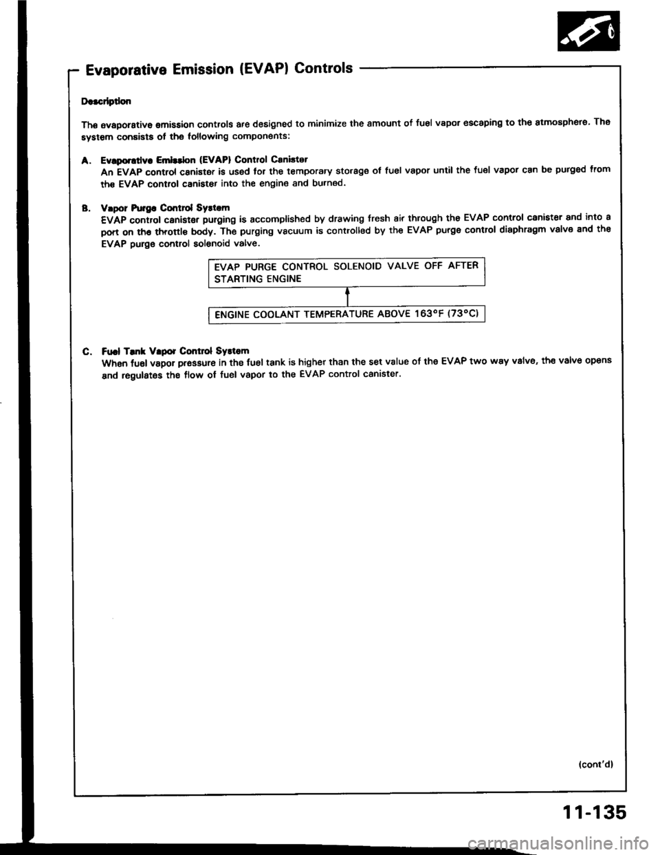
Evaporative Emission (EVAPI Controls
Da.cdptlon
Thg avaporstive omission controls are designed to minimize the smount of fusl vapor escaping to the atmosphero. The
system conaists ot the following compon€nts:
Evlporttly. Emlttbn (EVAPI Control Caniltot
An EVAP control canistor is used lor the temporary storage ot fuel vapor until the fuel vapor can be purged lrom
th€ EVAP control canister into the engin€ and burned.
vlpor hr]gG Cmt]ol Syst m
€VAp control canistgr puroing is accomplished by drawing fresh air through tho EVAP control canister and into a
pon on th6 throttl€ body. Th€ purging vacuum is controllsd by the EVAP purge control diaphragm valve end the
EVAP purge control solenoid valve.
C. Ft|.l Tmk Vlpor Control Systom
When fuel vapor prassure in the fuel tank is higher than the set v8lue of the EVAP two way v8lv6, th€ valve opens
and regulates the flow ol fuel vapor to the EVAP control canister.
(cont'd)
11-135