Fuses
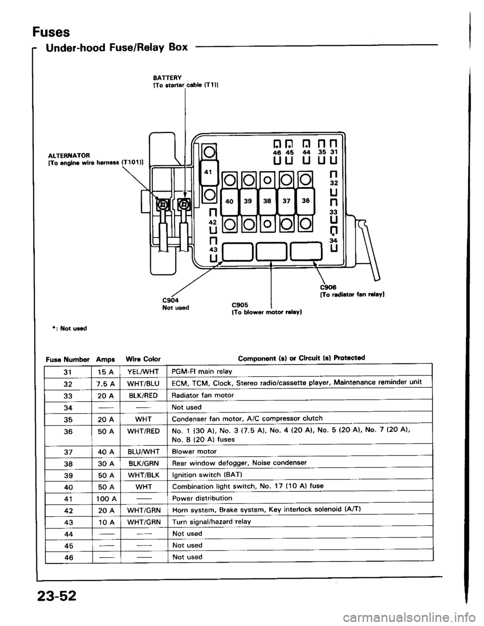
Under-hood Fuse/Relay Box
ALTERI{ATOR
fTo .ngino wlto hsrno$ {Tlolll
Not usod
r: l\lot u3.d
umborAmpsColor
nF n nn46 45 /t4 35 3l
UU U UU
n32
U
n
33
U
r:rg
U
n
42
U
n43
U
[To rldidor hn r.l.Yl
Componon! (sl 01 Clrcuit 13) Protoqtod
3115 AYEL/WHTPGM-Fl main relay
327.5 AWHT/BLUECM, TCM. Clock, Stereo radio/cassette plsyer, Maintenance reminder unit
a2204BLK/REDRadiator Jan motor
34Not used
35204WHTCondenser fan motor, A/C compressor clutch
50AWHT/REDNo. I {3O A), No. 3 (7.5 A). No. 4l2O Al, No 5 (2O A), No. 7 (2O A),
No. I (20 A) fuses
3740ABLU/lVHTBlower motor
3830ABLK/GRNRear window defogger, Noise condenser
?q50AWHT/BLKlgnition switch {BAT}
4050AWHTCombination light switch, No. 17 (1O Al fuse
41100 APower distribution
4220AWHT/GRNHorn system, Brake system, Key interlock solenoid (Aff)
4310 AWHT/GRNTurn signal/hazard.elay
44Not used
45Not used
46Not used
23-52
lgnition System
lgnition Timing lnspection and
Setting (cont'd)
5. To adjust ignition timing, loosen the distributor
mounting bolts, and turn the distributor housing
counterclockwise to advance the timing, or clock-
wise to retard the timing.
MOUNN G BOLTS24 N.m (2.4 kgl.m, 17 lbt'ftl
Tighten the adjusting bolts and recheck the timing.
Remove the SCS short connector trom the service
check connector.
2.
ldle Speed Inspection
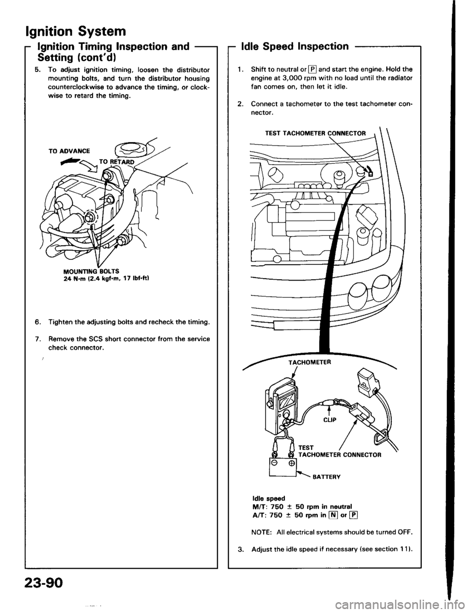
Shift to neutral or Ll] and start the engine. Hold the
engine at 3,OOO rpm with no load until the radiator
fan comes on, then let it idle.
Connect a tachometer to the test tachometer con-
nector.
ldle sp6od
M/T: 750 t 50 rpm in neuttal
A/T: 75O t 50 rpm in @ or @
NOTE: Allelectrical systems should be turned OFF.
Adjust the idle speed il necessary (see section 1 1).
b.
23-90
GAUTION:
o Eatora instdling tho steoring whosl, lha front whaelslhould bo alignod straight !ho!d.. Bc auro to imtalt tho hrrnass wiros so that th6y !16not pinchod or intsrt6ring with othor crr parts.. Aftor rsassambly. conlirm that tho whods lre 3tillturnad straight ahead and lh.t the steering wheolrpoko angle is corrsct {rosd tesi}. lf mino. spok€angl6 adiustmont is necols!ry, do 30 only by ldiust_mgnt ol tho tio-rod9. not by removing and rgposi-tioning tho rteering whoel.
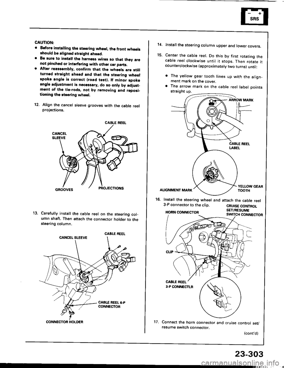
12. Align th€ cancel sleeve grooves with the cable reelprojections.
Carefully install th€ cable reel on the steering col-umn shaft. Then attach the connector holder to thesteering column.
CABLE REEL
CABI.I REEL
CONNECTOR HOLDER't7.
23-303
14.
t5.
Installthe steering column upper ano tower covers.
Center the cable reel. Do this by first rotating thecable reel clockwise until it stops. Then rotate itcounterclockwise (approximately two turns) until:
. The yellow gear tooth lines up with the align-ment mark on the cover.a The arrow mark on the cable reel label Dointsstraight up.
ABROW MARK
ALIGNMENT MARK
16. Install the steering wheel and3-P connector to the clip.
HORN CONNECTOR
YELLOW GEARTOOTH
attach the cable reel
CRUISE CONTROLSET/RESUME
Connect the horn connector and cruise control sevresume switch connector.
(cont'd)


