Page 98 HONDA INTEGRA 1994 4.G Workshop Manual
[x] Cancel search | Manufacturer: HONDA, Model Year: 1994, Model line: INTEGRA, Model: HONDA INTEGRA 1994 4.GPages: 1413, PDF Size: 37.94 MB
Page 651 of 1413
Power Steering Pump
lnstallation
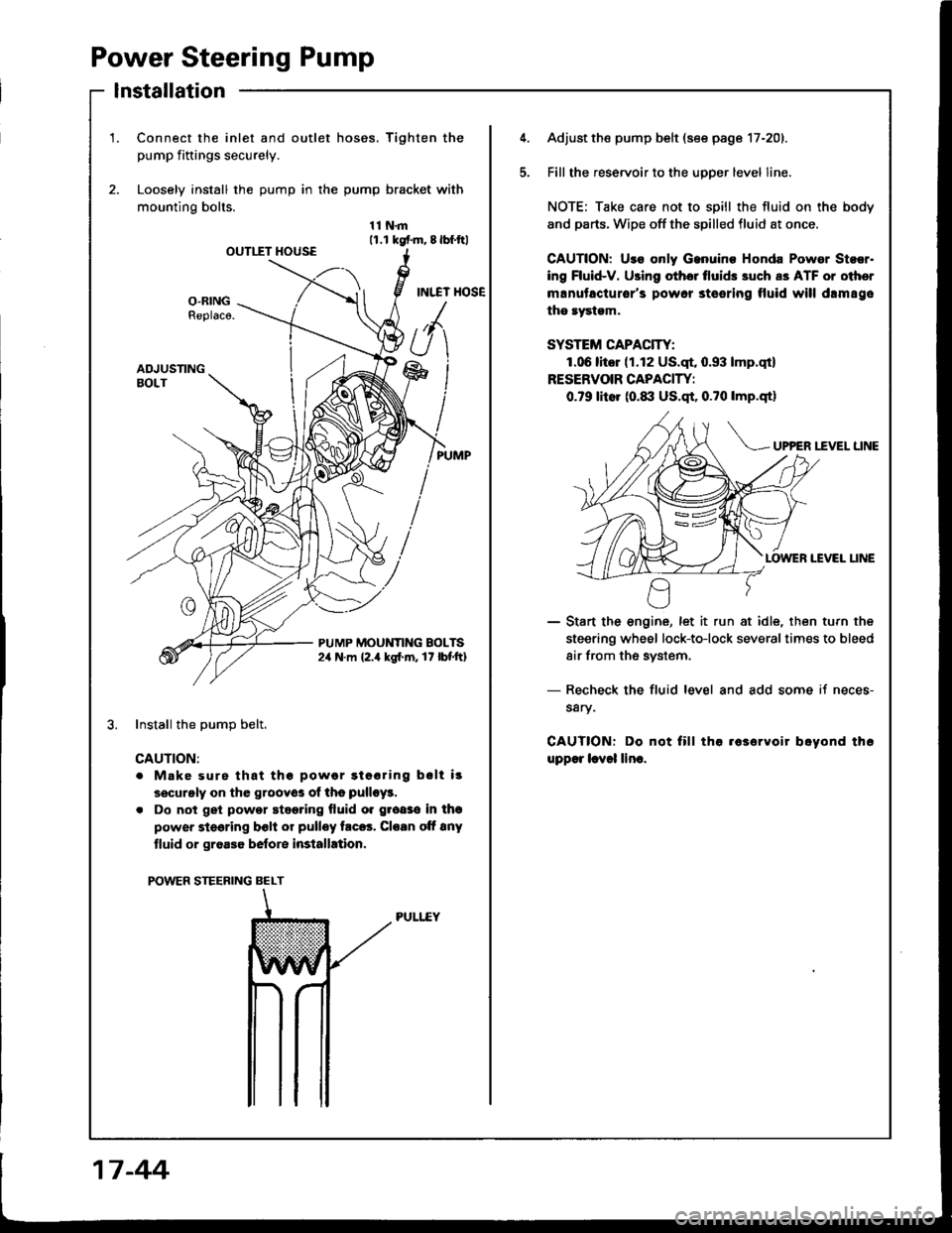
1.Connect the inlet and outlet hoses. Tighten the
pump fiftings securely.
Loosely install the pump in the pump bracket with
mounting bolts.
11N.m11.r kgf.m, 8lbf.ftlOUTIIT HOUSE
INI.TT HOSEO-RINGReplaco.
ADJUSTINGBOLT
PUMP MOUNTING BOLTS2,r N.m {2.4 kgl.m. 17 lbf'ft}
Install the DumD belt.
CAUTION:
. Make surs that thg powor gtooring bslt i!
securgly on the grooyos of ths pulloy!.
. Do not get powor stggring fluid o. groaso in thg
power steering bclt or pulley trc6. Cloan oft 8ny
tluid or groa36 belore installation.
POWER STEERING BELT
PULI..EY
5.
Adjust the pump belt (see page 17-201.
Fill the reservoir to the uoDer level line.
NOTE; Take care not to spill the fluid on the body
and parts. Wipe off the spilled fluid at once.
GAUTION: Uro only Ganuino Honda Powor Stsor.
ing Fluid-V. Using othor tlui& 3uch a3 ATF or oiher
manutacturor's powor steering tluid will drm89e
the rystgm.
SYSTEM CAPACITY:
1.06litor (1.12 US.qt, 0.93 lmp.qt)
RESERVOIR CAPACIW:
0.79 litor (0.1|:| US.qt, 0.?0 lmp.qtl
UP?ER I.fVEL LINE
IEVEI LINE
- Start the engine, let it run at idle, then turn the
steering wheel lock-to-lock severaltimes to bleed
air from the system.
- Recheck the fluid level and add some if neces-
s8ry.
CAUTIONT Do not fill tha .63ervoir boyond th6
upp€r lcvol lino.
17 -44
Page 652 of 1413
Steering Gearbox
Removal
NOTE: Using solvent and a brush, wash any oil and dirt
off the valve body unit, its lines, and the end if the gear-
box. Blow dry with compressed air.
1. Drain the power steering fluid as described on page
17 -21.
2. Rsise the front of car, and support on safety stands
in the propsr locations (see section 1).
3. Remove the front wheels.
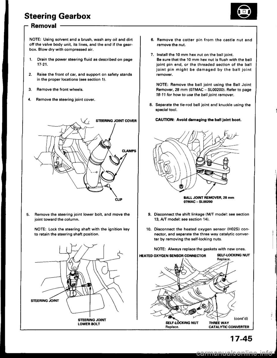
il. Removs the st€ering joint cove.,
SIEERING JOIi{T COVEB
Remove the steering joint lower bolt, and move thejoint toward the column.
NOTE: Lock the steering shaft with the ignition key
to retain the steering shaft position.
Remove the cotter pin trom the castle nut and
removo the nut.
Installthe 10 mm hex nut on the balljoint.
Be sure that ths 10 mm hex nut is flush with the ball
ioint pin end, or the threaded section of the ball
ioint pin might be damaged by the ball iointremover.
NOTE: Remove the ball joint using the Ball Joint
Remover, 28 mm {07MAC - 5100200}. Refer to page
l8-11 fot how to use the ball joint rcmover,
Separat€ the tie-rod ball joint and knuckle using the
soscialtool.
CAUTION: Avold d.maging th. blllloint boot.
BALL JOlt{T REMOVER. 28 mm07MAC - SLqt2|X)
Disconnect the shift linkage {MfI model: see section
13, A/[ model see section 14).
Disconnect the heated oxygen sensor (H02S) con-
ngctor, and separate the three way catalytic conver-
ter by removing the s€lf-locking nuts.
NOTE: Always replace the gaskets with new ones.
OXycEt{S€NSOnOONNECTOR SELF.LOCKINGNUT
{cont'd)IHREE WAYCA?ALYTIC CONVERTEN
8.
10.
HEATED
Replacs.
17-45
Page 655 of 1413
Steering Gearbox
Disassembly
Stssring Rack Disassembly
NOTE:
. Before disassembling the gearbox, wash it off with
solvent and a brush.
. Do not dip seals and O-rings in solvent.
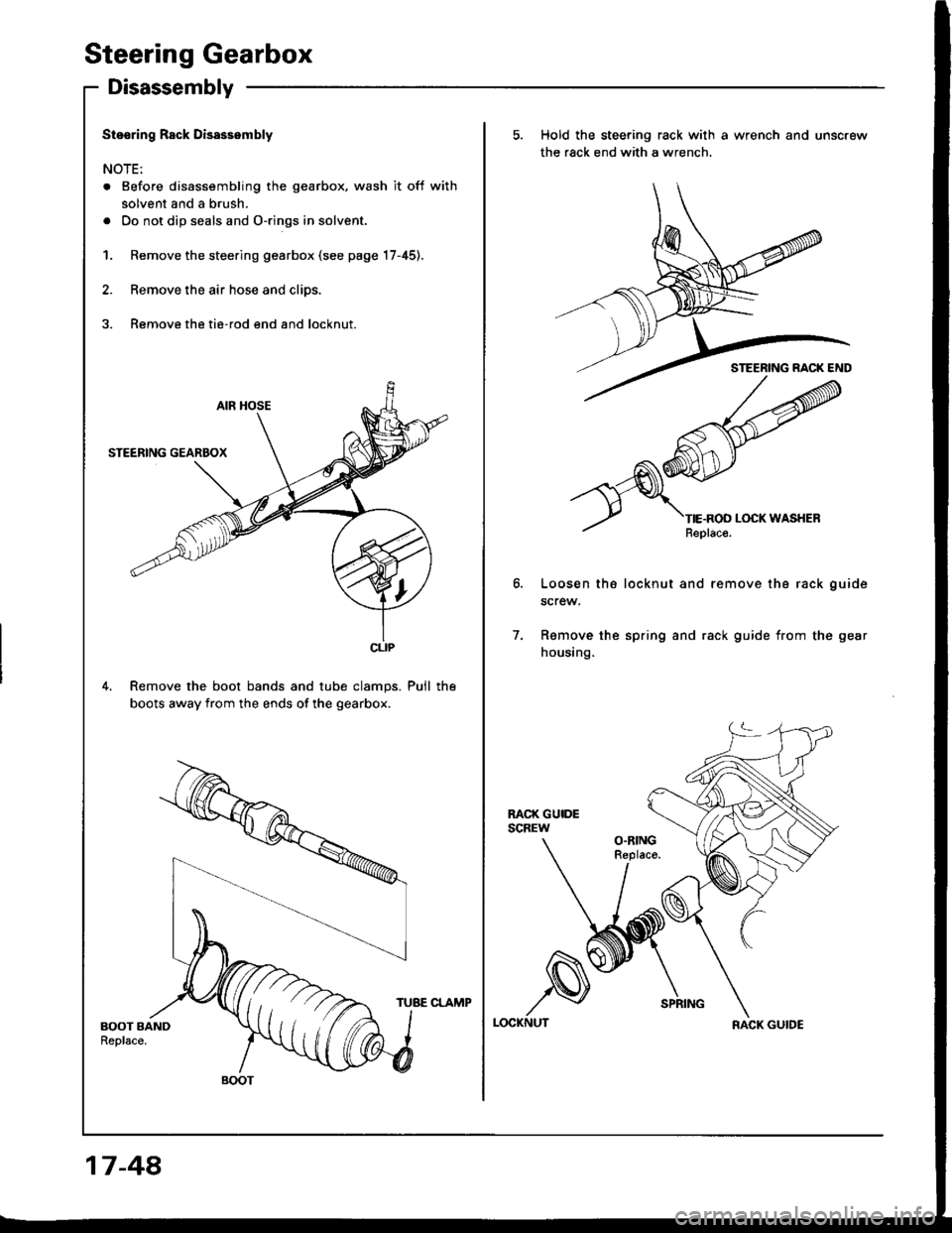
1. Remove the steering gearbox (see page 17-45).
2. Remove the air hose and clips.
3. Remove the tie-rod end and locknut.
4. Remove the boot bands and tube clamps. Pull the
boots away from the ends of the gearbox.
CLIP
BOOT
5. Hold the steering rack with a wrench and unscrew
the rack end with a wrench.
Loosen th6 locknut and remove tha rack guide
screw.
Ramove the spring and rack guide from the gear
housing.
7.
LOCKNUTRACK GUIDE
17-48,
TUBE CLAMP
Page 656 of 1413
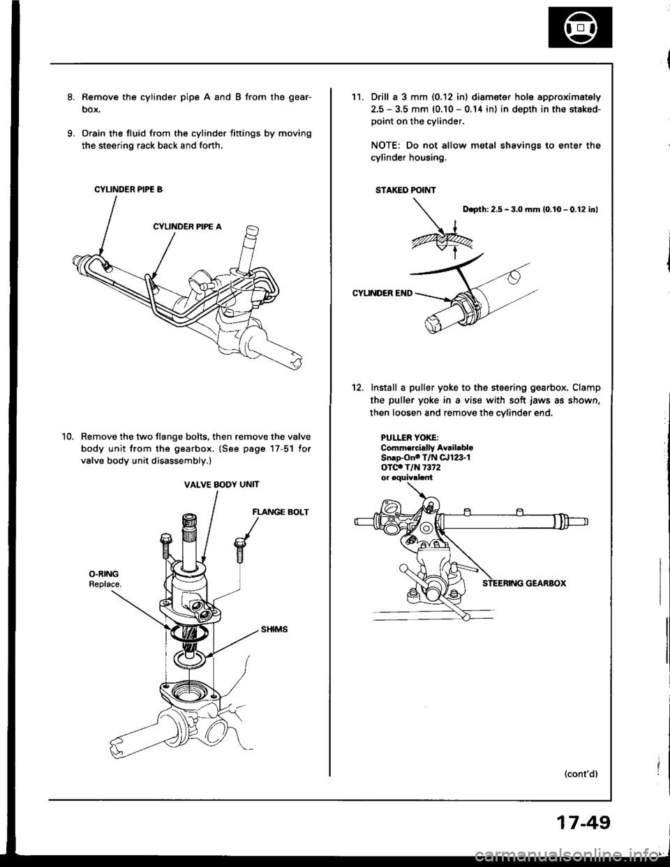
Remove the cylinder pipe A and B from the gear-
box.
Drain the fluid from the cylinder fittings by moving
the steering rack back and forth,
Remove the two flange bolts, then remove the valve
body unit from the gearbox. {See page 17-51 for
valve body unit disassembly.)
FLANGE BOLT
CYLINDER PIPE B
VALVE BODY UNIT
11.Drill a 3 mm {0.12 in) diameter hole approximately
2.5 - 3.5 mm (0.10 - 0.14 in) in depth in the staked-
point on the cylinder.
NOTE: Do not allow metal shavings to enter the
cylinder housing.
STAKEO POINT
D.prh:2.5 - 3,0 mm 10.10 - 0.12 inl
CYUNDER END
12. Install a puller yoke to the stesring gearbox. Clamp
the puller yoke in a vise with soft iaws as shown,
then loosen and remove the cvlinder end.
PULLER YOKE:Commercirlly AvrilabloSn.p-Ono T/N qrie'-1
oTclo T/N 7372
(cont'd)
17-49
Page 667 of 1413
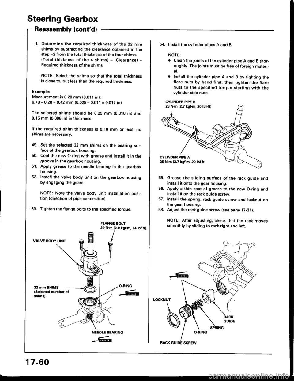
Steering Gearbox
Reassembly lcont'd)
-4. Determine the requifed thickness of the 32 mm
shims by subtracting the clearance obtained in thestep -3 from the total thickness of the four shims.(Total thickness of the 4 shims) - (Clearance) =
Required thickness of the shims
NOTE: Select the shims so that th6 total thicknessis close to, but less than the required thickness.
Exampls:
Measu.ement is 0.28 mm (0.011 in):
0.70 - 0.28 = 0.42 mm (0.028 - 0.011 = 0.0't7 in)
The selected shims should be 0.25 mm (O.O1O in) and0.15 mm (0.005 in) in thickness.
lf the required shim thickness is 0.lO mm or less, no
shims are necessary.
i[9. Set the selected 32 mm shims on the bearing sur-face of the g€arbox housing.
50, Coat the new O-ring with gresse and install it in thegroove in the gearbox housing.
Apply grease to the needle bearing in the gearbox
housing.
Install the valve body unit on the gearbox housing
by engaging the gears.
NOTE: Note the valve body unit installation posi-
tion (direction of pipe connection).
Tighten the flange bolts to the specified torque.
FLANGE BOLT20 N.m (2.0 kgt m, 14lbf.ft)
VALVE BODY UNIT
ct.
O-RING
-ffiti
NEEOLE BEARING
_#{
17-60
BACK GUIDE SCREW
54. Installthe cylind6r pipes A and B.
NOTE:
. Clean the joints ofthe cylinder pipe A and B tho.-oughly. The joints must be free of foreign mat€.i-
at,
o Install the cylinder pipe A and B by tighting theflare nuts by hand first, then tighten the flarenuts to the specified torque starting with thecylinder side nuts.
CYLINDER PIPE B
Grease the sliding surface of the rack guide andinstall it onto the gear housing.
Apply a thin coat of grease to the n€w O-ring andinstall it on the rack guide screw.
Install the spring, rack guide screw and locknut onthe gear housing.
Adjust the rack guide screw (see page l7-21).
NOTE: After adjusting, check that the rack movessmoothly by sliding to rack right and left.
LOCKNUT
-6t
26 N.m (2.7 kg{.m,20lbtft)
Page 672 of 1413
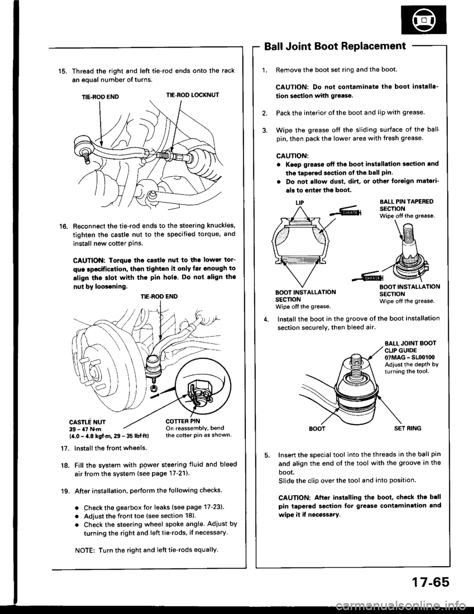
15.Thread the right and lefi tie-rod ends onto the rack
an eoual number of turns.
TIE-ROO ENDTIE.ROD LOCKNUT
R€connect the tie-rod ends to the steering knuckles,
tighten the castle nut to the specified torque, and
install new cotter pins.
CAUTION: Iorquo tho castle nut to tho lower tor-
que lpocification, thsn tighton it only far cnough to
align thc slot with tho pin hole. Do not align tho
nut by loosoning.
CASILE NUT39 - 47 N.m14.0 - a.8 kgf.m. 29 - 35 lbf ftl
17. lnstallthe front wheels.
18. Fill the system with pgwer steering fluid and bleed
air from the system (see page 17-21).
19. After installation. perform the following checks.
. Check the gearbox Jor leaks (see page 17-231
. Adjust the front toe (see section 18).
o Check the steering wheel spoke angle. Adjust by
turning the right and left tie-rods, if necessary.
Ball Joint Boot Replacement
Remove the boot set ring and the boot.
CAUTION: Do not contaminate ihe boot in3talls-
tion section with gr€aso.
Pack the interior of the boot and lip with grease.
Wipe the grease off the sliding surface of the ball
pin, then pack the lower area with fresh grease.
CAUTION:
. Ke€p g;eass off the boot in3tallation section and
tho laperad section of the ball pin.
. Do not altow dust, di.t, or other toreign mat6ti-
als to enter tho boot,
LIPBALL PIN TAPEREDSECTIONWipe off the grease.
BOOT INSTALLATIONSECTIONwiDe off the grease.
BOOT INSTALLATIONSECTIONWipe off the grease.
COTTER PINOn reassembly, bendthe cotter pin as shown.
Install the boot in the groove ot the boot installation
section securely, then bleed air.
SALL JOINT BOOTCLIP GUIDE07MAG - SL(x)l00Adiust the depth byturning the tool.
SET RING
Insert the special tool into the threads in the ball pin
and align the end of the tool with the groove in the
boot.
Slide the clip over the tool and into position
CAUTION: After installing the boot, check th. b.ll
pin taperod section tor grease contamiration and
wipe it if nocossary.
NE.ROD END
Turn the right and left tie-rods equally.
17-65
Page 914 of 1413
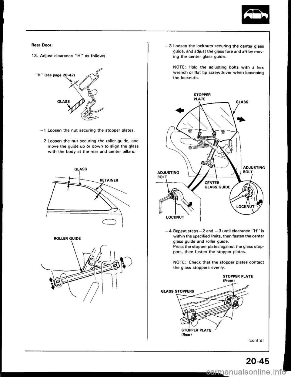
R6ar Door:
'13. Adjust clearance "H" as follows.
"H" lsos page 20-421
- 1 Loosen the nut securing the stopper plates.
2 Loosen the nut securing the roller guide, and
move the guide up or down to align the glass
with the body at the rear and center pillars.
GLASS
ROLLER GUIDE
-3 Loosen the locknuts securing the center glass
guide, and adjust the glass fore and aft by mov-
ing the center glass guide.
NOTE: Hold the adjusting bolts with a hex
wrench or tlat tip screwdriver when loosening
the locknuts.
I
-4 Repeat steps-2 and -3 until clearance "H" is
within the specified limits. then fasten the center
glass guide and roller guide.
Press the stopper plates against the glass stop-
pers, then fasten the stopper plates.
NOTE: Check that the stopper plates contact
the glass stoppers evenly.
STOPPER PLAYElF ontl
204s
Page 915 of 1413
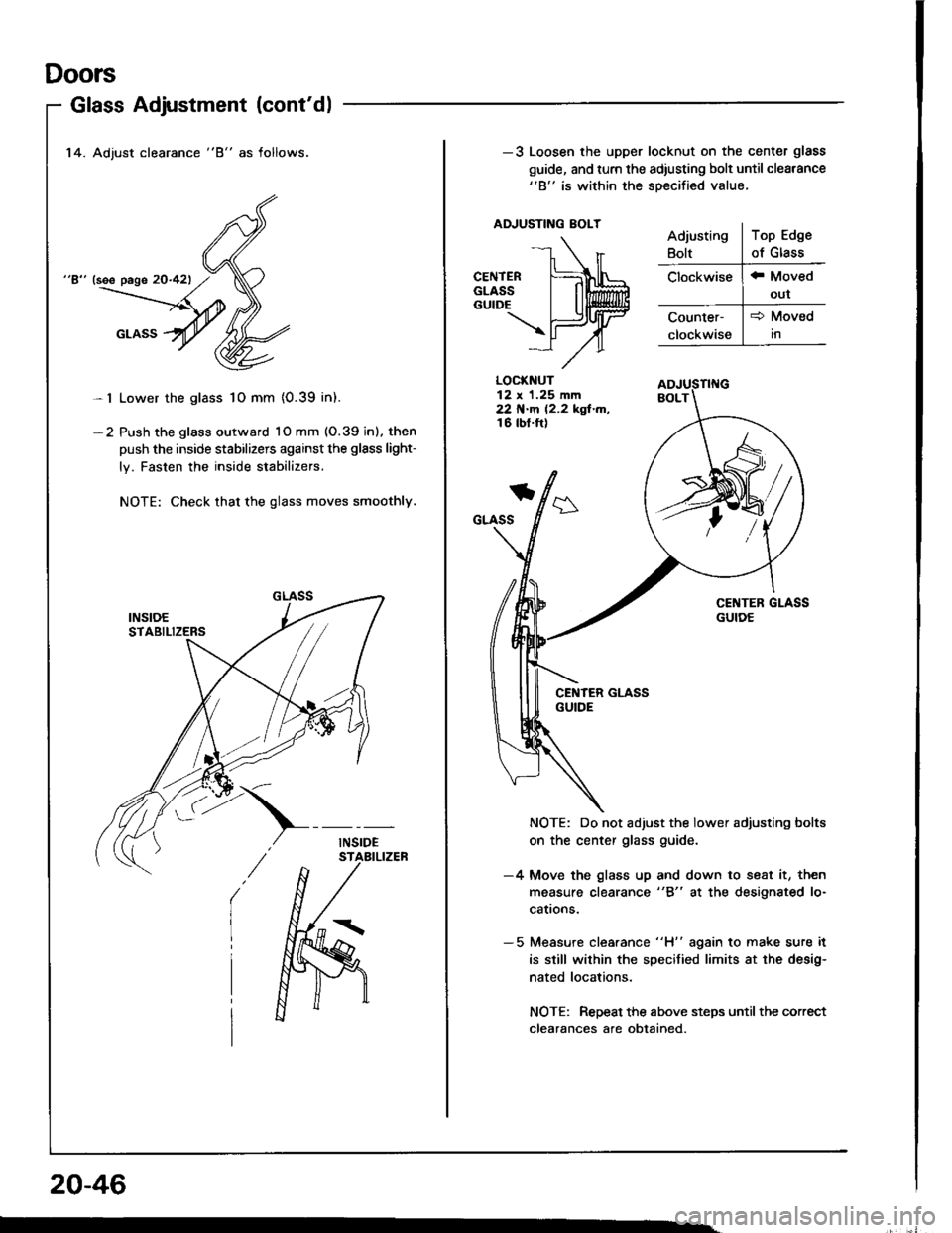
Doors
14. Adjust clearance "8" as follows.
"8" (see page 20-421
Lower the glass 1O mm {0.39 in).
Push the glass outward 1O mm (O.39 inl. then
push the inside stabilizers against the glsss light-
ly. Fasten the inside stabilizers.
NOTE: Check that the glass moves smoothly.
Glass Adjustment (cont'dl
-l
-2
20-46
-3 Loosen the upper locknut on the center glass
guide, and turn the adiusting bolt until cleatance"B" is within the soecified value.
ADJUSTING EOLT
LOCKNUT12 x 1.25 mm22 N.m 12.2 kgf.m,16 tbt.ft)
*
GLASS
NOTE: Do not adjust the lower adjusting bolts
on the center glass guide.
-4 Move the glass up and down to seat it, then
measure clearance "8" at the designated lo-
cattons.
- 5 Measure clea.ance "H" again to make sure it
is still wilhin the specified limits at the desig-
nated locations.
NOTE: Repeat the above steps until the correct
clearances afe obtained.
Page 916 of 1413
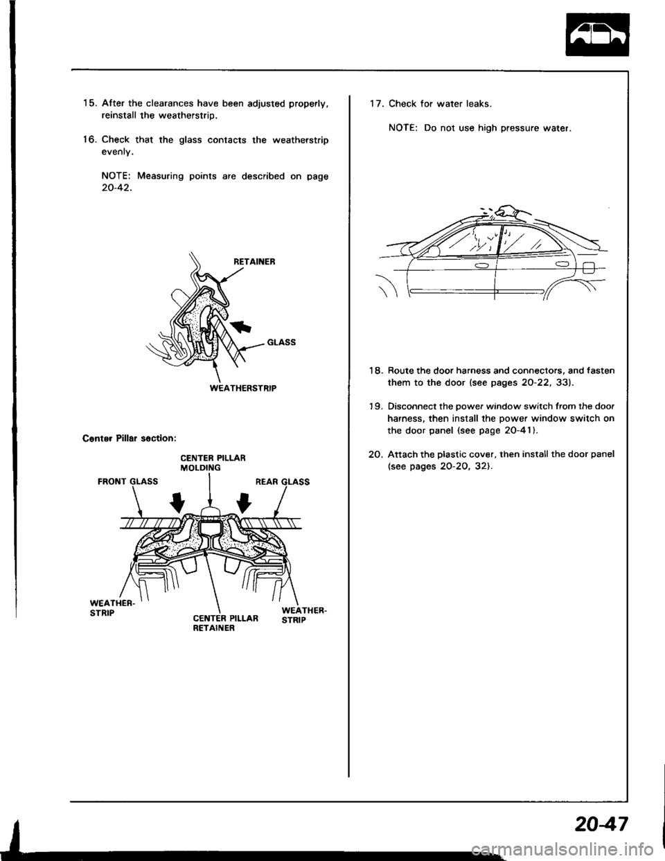
15. After the clearances have been adjusled properly.
reinstall the weatherstrip.
16. Check that the glass contacts the weatherstrip
evenly.
NOTE: Measuring points are described on page
20-42.
Conter Pillar soction:
WEATHERSTRIP
17.Check for water leaks.
NOTE; Do not use high pressure water.
18. Route the door harness and connectors, and fasten
them to the door (see pages 20-22, 331.
19. Disconnect the oowef window switch from the doo.
harness, then install the power window switch on
the door panel (see page 20-41).
2O. Attach the plastic cover, then install the door panel
(see pages 2O-2O, 321.
2047
Page 918 of 1413

Mirrors
Power Door Mirror Replacement
Hstchback
1. Pry out the cover panel with a flat tip screwdriver,
then remove it.
CAUTION: When prying with a flat tip screwdriver.
w'ap it whh protoctiva tapo to pravont damage.
2. Disconnect the connector. Remove the nuts, then
remove the door mirror while holdino it.
< : Nut locltion3, 3
^^ sxo.8mm I
l$9 111 - to.+ rst.. i| +|lmtu.+rgr.m, I3 lbl'lrl - ---J'/
cot{t{EcToB(Doo. mirror ddol
DOOR MIRROR
CONNECTORlDoor harnoss.ide)
CONNECTOR
3. Installation is the reverse o{ the removal procedure.
Sedan
1. Remove the door panel (see page 20-201 and dis-connect the connector.
2. Pry the cover panel out with a flat tip screwdriver,
then remove the cover panel.
CAUTION: Whsn prying with a flat tip scrowd.lv€l,
wrap it with protectiv€ taps to p.svont damag6.
3. Remove the screws while holding the door mirror.
< i Scrow locations
, A< : Scrow, 2 , B< : Scr6w, I
! ,"",''@ I 66
I s'0.4.- | sro.'"e-.
4 N.m (0.4 kst.m, + w.m (0.4 kgt.m,\3_!!t.rrr__ \!Lbllq
CONNECTOR
4. Installation is the reverse of the removal procedure,
HOOKS
20-49