Page 98 HONDA INTEGRA 1994 4.G Workshop Manual
[x] Cancel search | Manufacturer: HONDA, Model Year: 1994, Model line: INTEGRA, Model: HONDA INTEGRA 1994 4.GPages: 1413, PDF Size: 37.94 MB
Page 619 of 1413
Troubleshooting
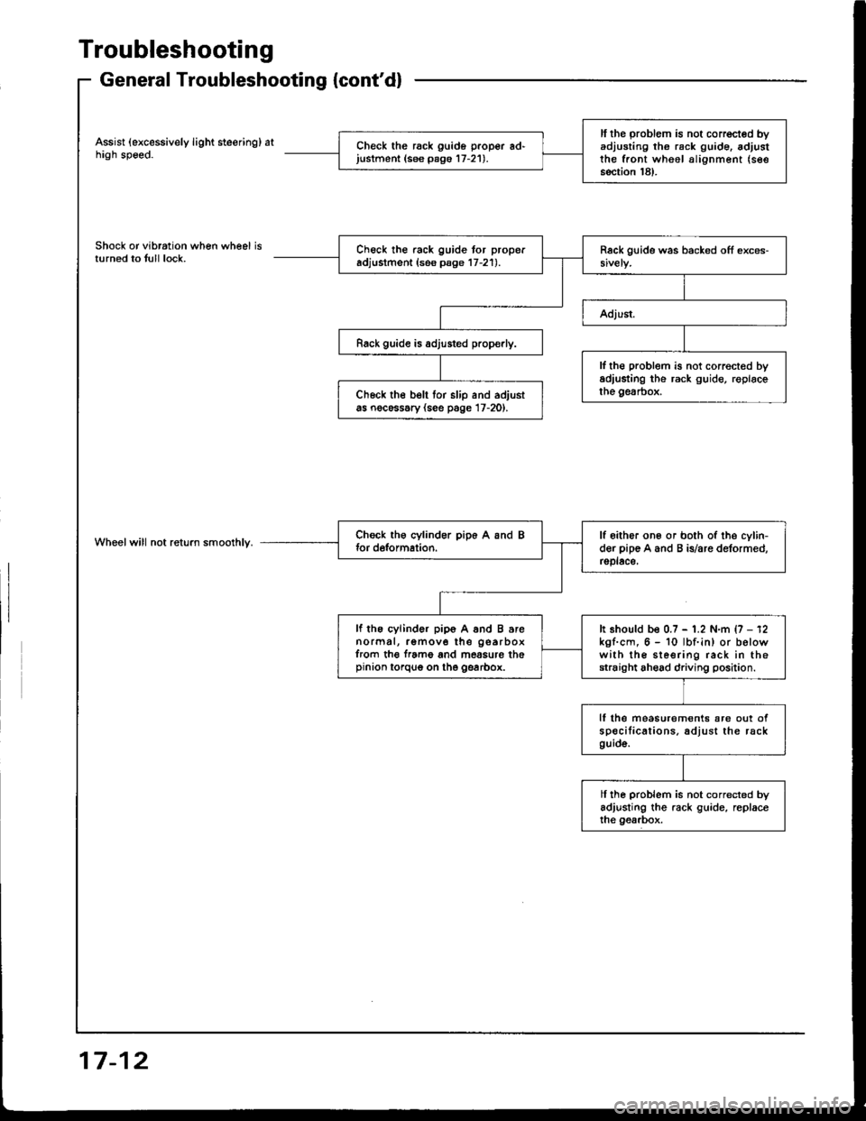
General Troubleshooting {cont'd}
Assist (excessively light steering) athigh speed.
Shock or vibration when wheel isturned to tull lock.
Wheelwill not return smoolhly.
ll the problem is not corrected byadjusting th6 rack g!ide. adjustthe front wheel alignment (see
section 18).
Check the rack guido proper ad'justment (see pago 17-21).
Check the rack guide tor properadjustment (ses psge 17-21).
Rack guide is adjusted prop€rly.
lf th€ problem is not correct€d byadiusting the rack guide, roplacethe gesrbox.Ch6ck the belt tor slip and adjustas nocessary (see page 17-20).
lf oither one or both of the cylin-der pip€ A and B is/are deformed,rsplace,
lf the cylinder pip6 A and B arenormal, remove the gearboxfrom th€ f.ame and mossure thepinion torqug on the gearbox.
It should be 0.7 - 1.2 N.m {7 - 12kgf.cm, 6 - 10 lbf.in) or belowwith the sleering rack in thestraight ahead driving position.
lf lhe measurem€nts are out ofspecilications. adjust the rackguid6.
ll ihe problem is not corrected byadjusting the rack guide, replaceihe gearbox.
17-12
Page 620 of 1413
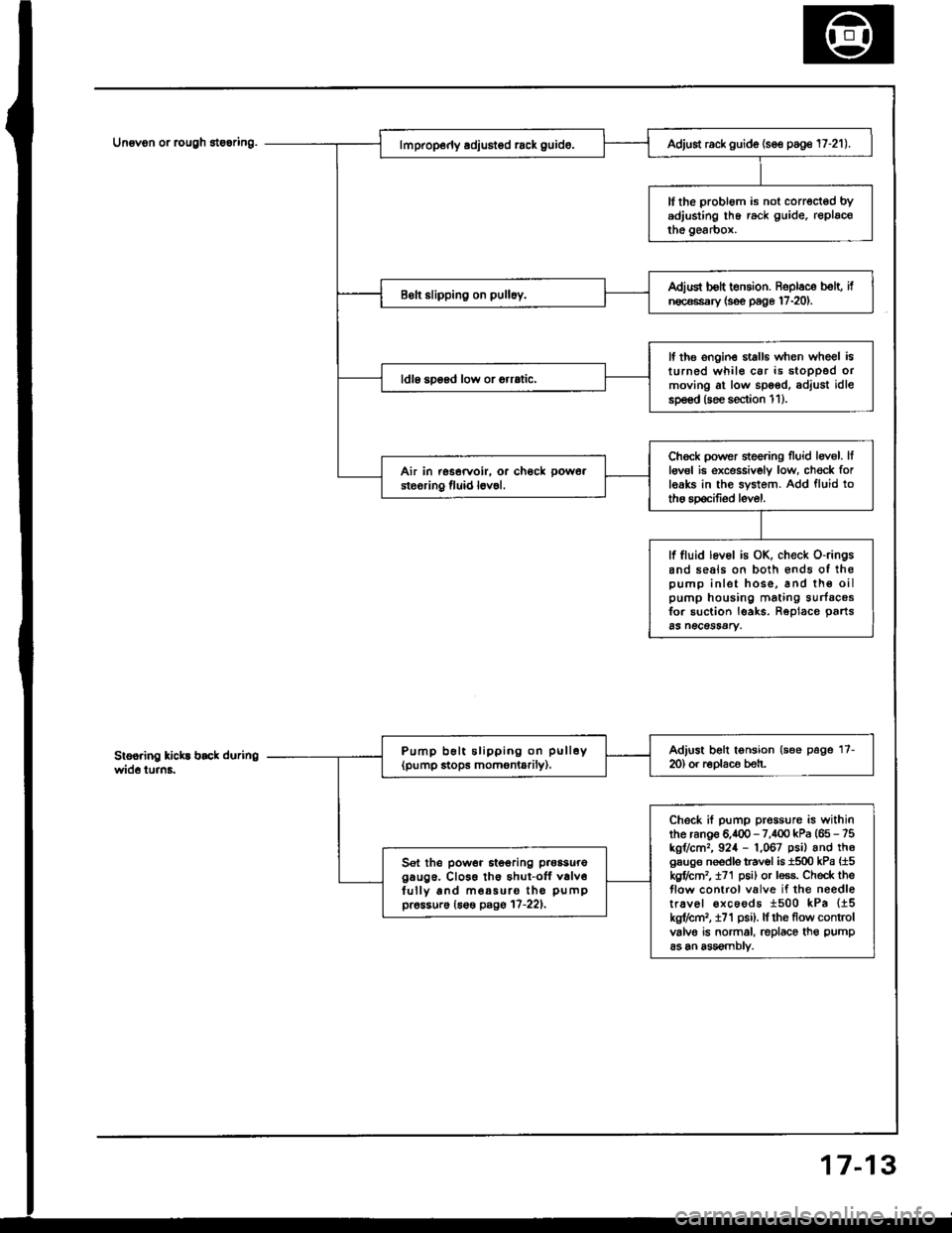
Unovon or rcugh 8te6ring.
3
Adjust rack guide (se€ poge 17-21).
ll the probl6m is not corrected bYadjusting lhe rack guide. replacothe gearbox.
Adiud bolt t€nsion. Roplace b€lt, ifn€c€ssary {s€e page 17-20).
lf the ongin€ stalls when wheel isturned whil€ car is stoDPed ormoving at low spoed, adjust idlesp€€d (soe section 1 1 ).
ldl6 soosd low or orrrtic.
Chock power sieering Iluid levol. Itlgv6l ie excessivoly low, ch€ck forleaks in the system. Add fluid totho spocifiod level.
Air in rssorvoir. or ch€ck pow6a
steoring fluid l6v6l.
lf fluid lev6l is OK, check o-ringsand seals on both €nds of ihopump inlet hose, and th€ oilpump housing mating surfacosfor suction leaks. Reolace oarts65 n€CeSSAry.
Adjust belt tonsion (see page 17-m) or r€Dlaco beh.Pump b6lt slipping on pull6y(pump stops momontarily).
Check if pump prossure is withinthe ranoe 6.400 - 7,100 kPa (65 - 75kgr/cm,, 924 - 1,067 psil and th6gsuge needls travol is 1500 kPa {15kgflctn2, t71 p6i) or less. Check theflow control valve if the needletr.vel €xcoods 1500 kPa {15kg?cm,, i71 psi). lf rhe flow controlvalvo is normal, replace th€ pump
as an assomblv.
Sel the power itooring p.oasuregaug6. Cl066 th€ shut-off v6lv6fully and m€a5uro tho pumppr6ssur6 (6s€ pagg 17-221,
7-1
Page 621 of 1413
Troubleshooting
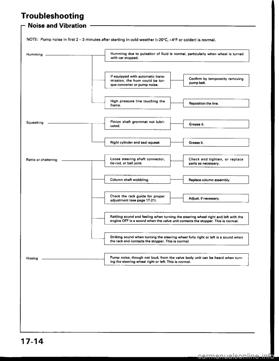
Noise and Vibration
NOTE: Pump noise in first 2 - 3 minutes after starting in cold weather (-20.C, -4"F or colder) is normal.
Humming
Rattle or chattering
Right cylinder end soal squeak
Pump noise. though not loud,lrom the vslvo bodv unit can be heard when turn-ing the steering wheel right or left. This is normsl.
Humming due to pulsation ol fluid is no.mal, paniculady when wheel is turnedwith ca. stopped.
lf equipped with automatic trans-mission, the hum could b€ tor-que convener or pump notse.
Confirm by temporarily removingpump b€lt.
High pressure line touching theframe,Reposhion tho line.
Loose steering shaft connector.tie-rod, or balljoint.Check and tighten, or replacepa s as necessary.
Column shaft wobbling.Replace column assembly.
Check the rack guide for properadjustment (16o page 17-21).Adjust, if n€ca€ssry.
Rattling sound and feeling when turning the steoring wheel right and lett with thoengine OFF is a sound when th6 valve unit contacts tho stopper. This is normal.
Striking sound wh6n turning the ste€ring whoglfully right o. left is a sound whenthe r6ck end contacts th6 stopper. This is normal.
17-14
Page 622 of 1413
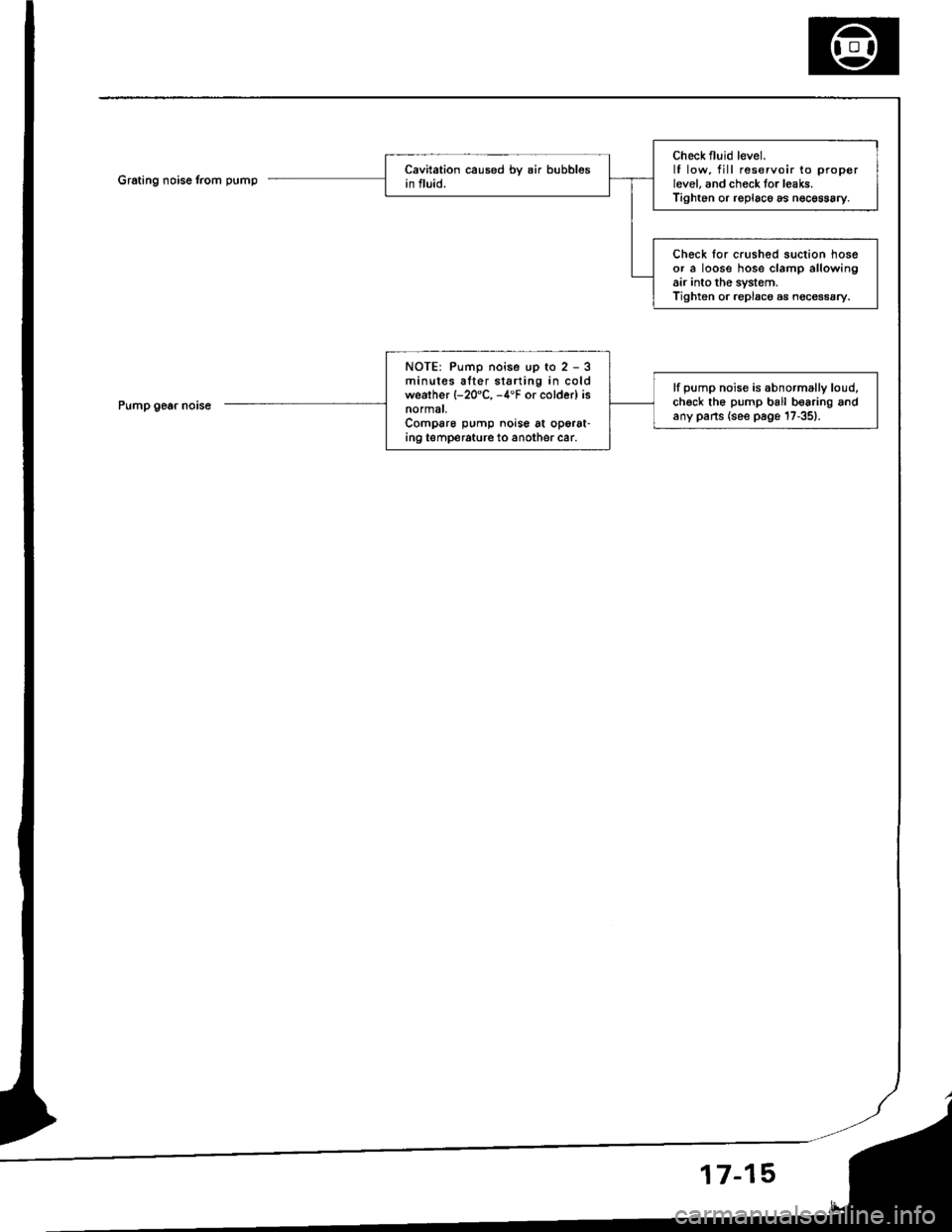
Grating noise from pump
Pump gear noise
Check fluid level.lf low. fill reservoir to properlevel, and check tor l€aks.Tighten or roplac6 as n€cessary.
Check for crushed suction hoseor a loose hose clamp allowingair into the system.Tighten or replace as noce$ary.
NOTE: Pump noise up to 2 - 3minutes alter starting in coldweather (-20'C, -4'F or colder) isnormat,Comparo pump noise at operat-in9 temperature to another car.
lf pump noise is abnormally loud,chgck the pump ball b€aring andany pans (see page 17-351.
17-15
Page 625 of 1413
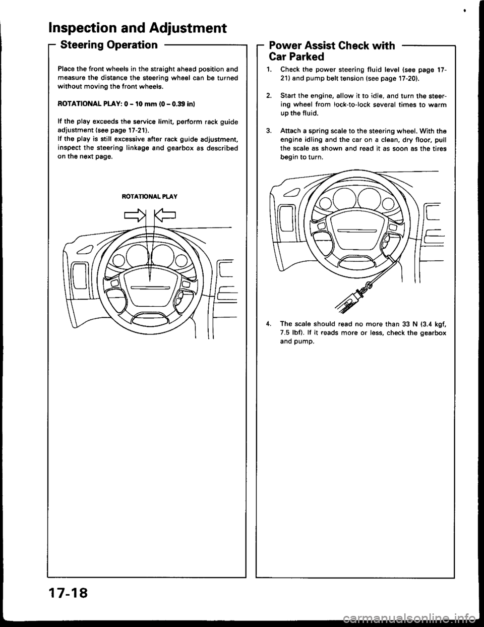
Place the front wheels in the straight ahesd position and
measure the distSnce the steering wheel can be turned
without moving the front wheels.
ROTATIONAL PLAY: 0 - 10 mm l0 - o.:Xl inl
lf the plsy excseds the service limit, psrform rack guide
adjustment (see page 17-211.
lf the play is still excessive after rack guide adjustment,
inspect the stsering linksgo and gearbox as described
on the next page.
ROTANONAL PLAY
Inspection and Adjustment
Steering OperationPower Assist Gheck with
817-1
Gar Parked
1. Check the power steering fluid level (see page 17-
21) and pump belt tension lsee page l7-20).
2.Start the engine, allow it to idle, and turn the steer-
ing wheel from lock-to-lock sev€ral times to warm
uo the fluid.
Attach a spring scale to the steering wheel. With the
engine idling and the car on a clean, dry floor, pull
the scale as shown and read it as soon 8s the tires
begin to turn,
il. The scal6 should read no more than 33 N (3.4 kgf,
7.5 lbf). lf it reads more or less, ch€ck the gearbox
and pump.
Page 628 of 1413
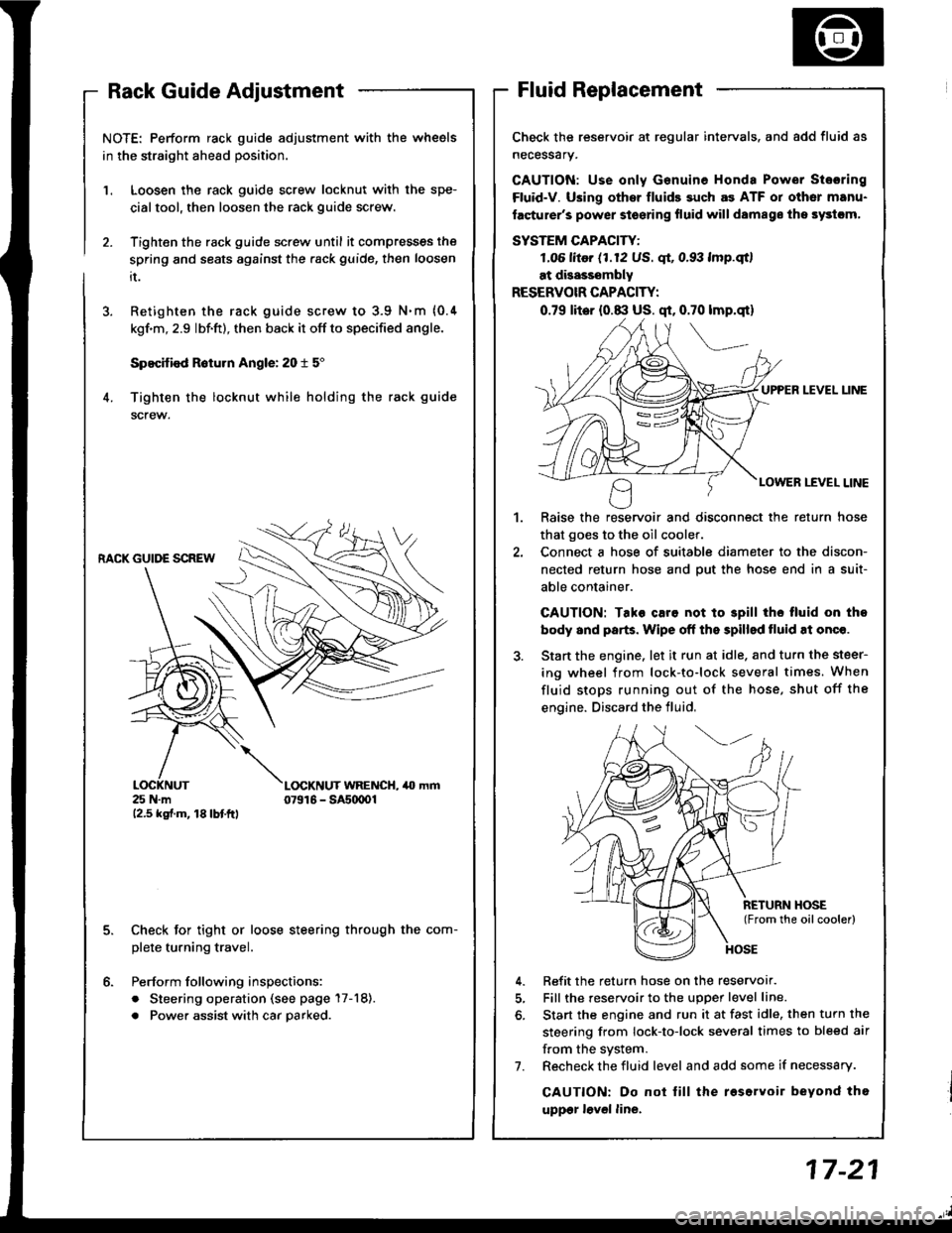
NOTE: Perform rack guide adjustment with the wheels
in the straight ahead position.
Loosen the rack guide screw locknut with the spe-
cialtool, then loosen the rack guide screw.
Tighten the rack guide screw until it compresses the
spring and seats against the .ack guide, then loosen
it.
Retighten the rack guide screw to 3.9 N.m {0.4
kgf'm, 2.9 lbf.ft), then back it off to specified angle.
Specified R6turn Angle: 20 t 5"
Tighten the locknut while holding the rack guide
screw.
1.
6.
RACK GUIDE SCREW
25 N.m12.5 kgf.m, 18lbtftl
L(rcKNUT WRENCH, 40 mm07916 - SAs(xtOl
Check for tight or loose steering through the com-
plete turning travel.
Perform following inspections:
. Steering operation (see page 17-18).
. Power assist with car parked.
Check the reservoir at regular intervals. and add fluid as
necessary.
GAUTION: Use only Genuine Honda Power Stosring
Fluid-V. Using othsr fluids such as ATF or other manu-
facturer's power stoering fluid will damags ths systcm,
SYSTEM CAPACITY:
LO6 litor (1.12 US. qt, 0.93 lmp.qtl
at disasssmbly
RESERVOIR CAPACITY:
0.79 lit6r (0.8:l US. qt, 0.70 lmp.qt)
UPPER LEVEL UNE
LOWER LEVEL LINE
,l
Raise the reservoir and disconnect the return hose
that goes to the oil cooler.
Connect a hose of suitable diameter to the discon-
nected return hose and put the hose end in a suit-
able container.
CAUTION: Tako caro not to 3pill tho tluid on tho
body and parts. Wipe off the spilled tluid at onqe.
Start the engine. let it run at idle. and turn the steer-
ing wheel from lock-to-lock several times. When
fluid stops running out of the hose, shut off the
engine. Discard the fluid,
Refit the return hose on the reservor.
Fill the reservoir to the uDoer level line.
Start the engine and run it at fast idle, then turn the
steering from lock-to-lock several times to bleed air
f.om the system.
Recheck the fluid level and add some if necessary.
CAUTION: Do not lill the roservoir beyond tho
uppgr lovel line.
7.
Page 635 of 1413
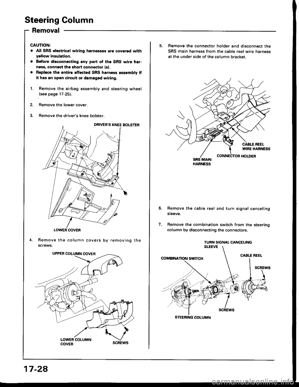
Steering Golumn
Removal
LOWER COVER
Remove the column covers
screws.
CAUTION:
. All SRS el€ctrical wiring hlrnesses are coversd withyollow insuhtion.
. Bctore dieconnocting any part ol tho SRS wiro h!r-
nesa, connoct the thort connector (s).
. Roplace tho ontire aftected SRS harness asr€mbly if
it has !n open circuit or d!mlgod wiring.
Remove the airbag assembly and steering wheel
.(see page 17-25).
Remove the lower cover.
Remove the driver's knee bolster.
by re mov in g the
17-2A
scREws
5. Remove the connector holder and disconnect the
SRS main harness from the cable reel wire ha.ness
at the under side ot the column bracket.
HARNESS
Remove the cable reel and turn signal canceling
steeve.
Remove the combination switch from the steering
column by disconnecting the connectors,
TURN SIGNAL CANCELINGSlTEVE
COMA|NANON SW]TCH
7.
CABI..E REEL
STEERING COLUMN
Page 640 of 1413
7.
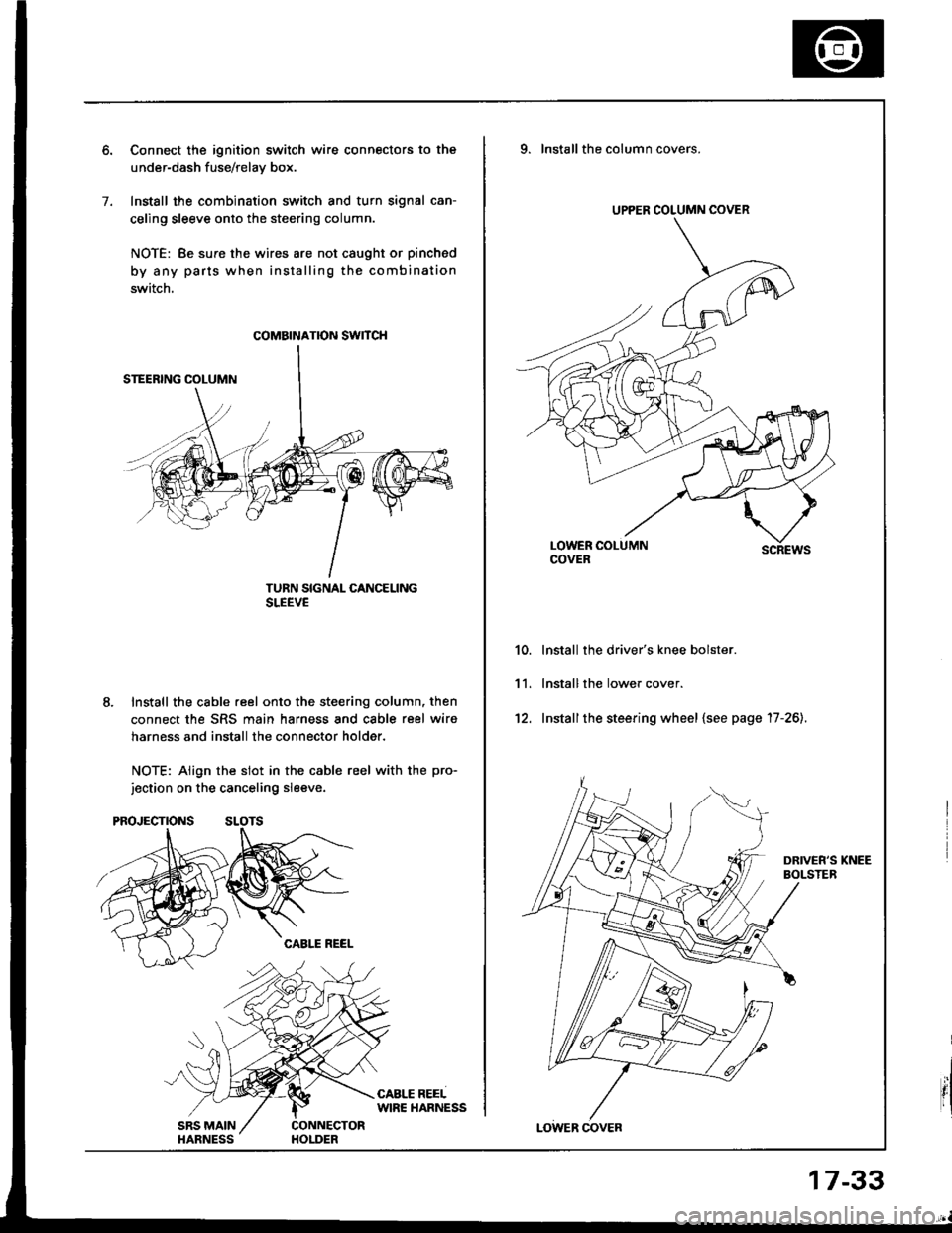
Connect the ignition switch wire connectors to the
under-dash fuse/relav box.
Install the combination switch and turn signal can-
celing sleeve onto the steering column.
NOTE: Be sure the wires are not caught or pinched
by any parts when installing the combination
switch.
TURN SIGNAL CANCELINGSLEEVE
Install the cable reel onto the steering column, then
connect the SRS main harness and cable reel wiro
harness and install the connector holder.
NOTE: Align the slot in the cable reel with the pro-
jection on the canceling sleeve.
coMatNATroN swncH
UPPER COLUMN COVER
9. Installthe column covers.
scREws
lnstall the driver's knee bolster.
lnstall the lower cover.
Installthe steering wheel {see page '17-26).
10.
11.
't2.
17-33
Page 641 of 1413
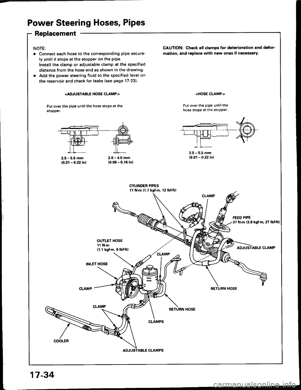
Power Steering Hoses, Pipes
Replacement
NOTE:
. Connect each hosg to the corresponding pipe securg-
ly until it stops at the stopp€r on the pipe.
Install the clamp or ad,ustable clamp at the specified
distancs from the hose end as shown in the drawing.
. Add the power steering fluid to the specilied level on
the reservoir and check fo. leaks (see page 17-23).
Put ov6r the pipe untilthe hose stops at the$opper.
CAUTION: Chock all clampsfor doterioration 8nd dstor-
mation, and rsplacG with new onss if n6co33!ry,
Put over the pipe untilthehose stops at the stopper.
2.5 - 5.5 mm
{0.01 - 0.22 inl2.0 - 4.0 mm10.08 - 0.16 inl
2.5 - 5.5 mm10.01 - 0.22 in)
OUYI.fT HOSE11 N.m{1.1 kgl.m, 8 lbl.ftl
INI."ET HOSE
ABLE CLAMP
RETURN HOSE
coot"ER
CLAMPS
17 -34
CLAMPS
Page 644 of 1413
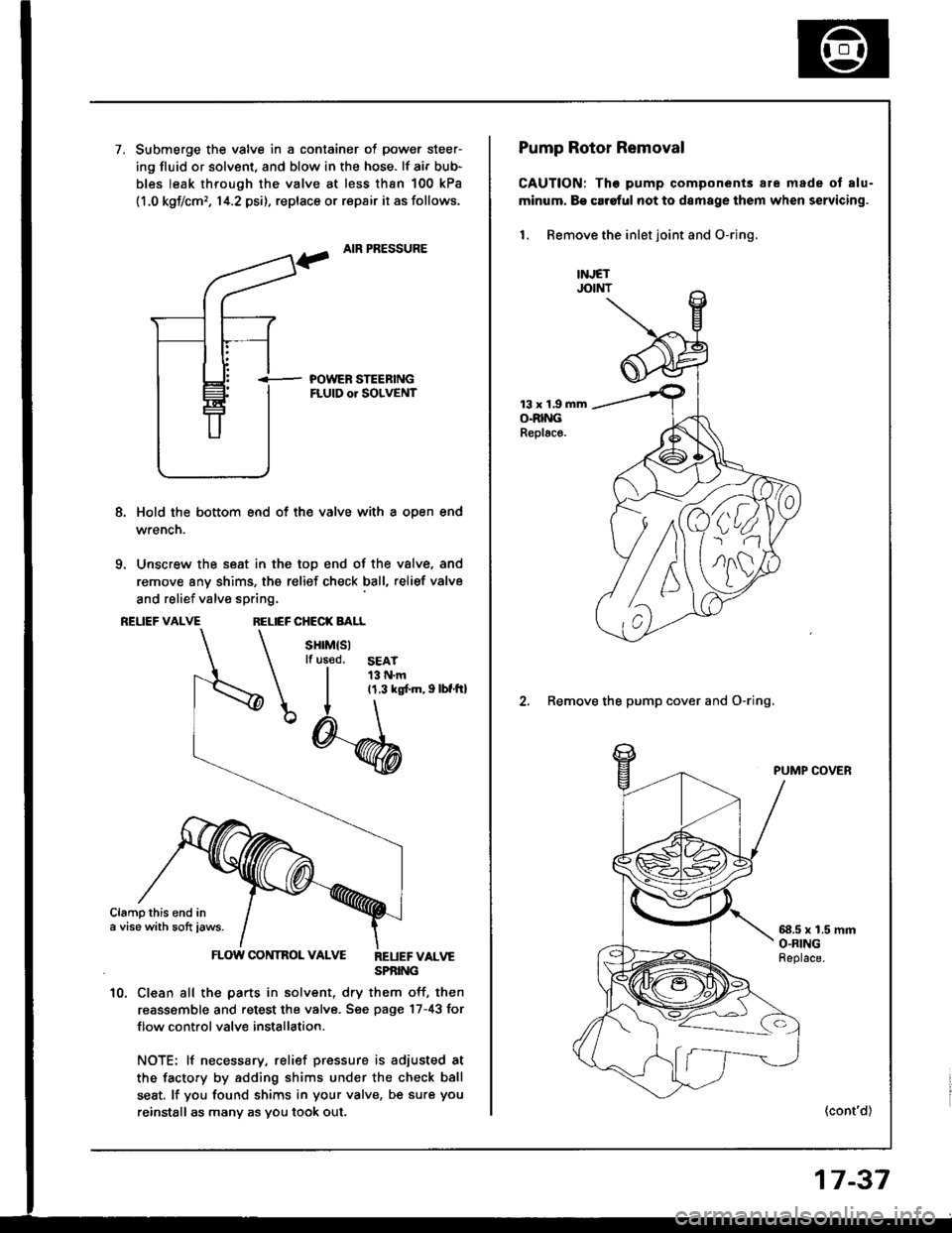
7.Submerge the valve in a container of power steer-
ing fluid or solvent, and blow in the hose. lf air bub-
bles leak through the valve at less than 100 kPa
11.0 kgf/cm,, 14.2 psi), replace or repair it as follows.
AIR PRESSURE
i- POWER STEEBINGFLUID or SOLVENT
8, Hold the bottom end of th€ valve with a oDen end
wrencn.
9. Unscrew the seat in the top end of the valve, and
remove any shims, the relief check ball, relief valve
and relief valve spring,
REUEF VALVERELIEF CHECK BALL
sHrM(sllf us€d.SEAT13 N.m11.3 ks[.m, I lbf.tt]
Clampthis end ina vise with sott iaws.
FLOW CONTROL VALVE REUEFvALvESPBING
10. Clean all the parts in solvent, dry them off, then
reassemble and retest the valve. Sge page 17-43 for
f low control valve installation.
NOTE: lf necessary, relief pressure is adiusted at
the facto.y by adding shims under the check ball
seat. lf you found shims in your valve, be sure you
reinstall as many as you took out,
')4.
nlll
Pump Rotor Removal
CAUTION: Tho pump components are made ot alu-
minum. B€ car6ful not to damage them when servicing.
1. Remove the inlet joint and O-rjng.
13 x 1.9 mmO.RINGReplac€.
2. Remove the pump cover and O-ring.
PUMP COVER
58.5 x 1.5 mmO.RINGFeplace.
(cont'd)
17-37