check engine HONDA INTEGRA 1994 4.G Owner's Manual
[x] Cancel search | Manufacturer: HONDA, Model Year: 1994, Model line: INTEGRA, Model: HONDA INTEGRA 1994 4.GPages: 1413, PDF Size: 37.94 MB
Page 164 of 1413
Grankshaft
Installation (cont'd)
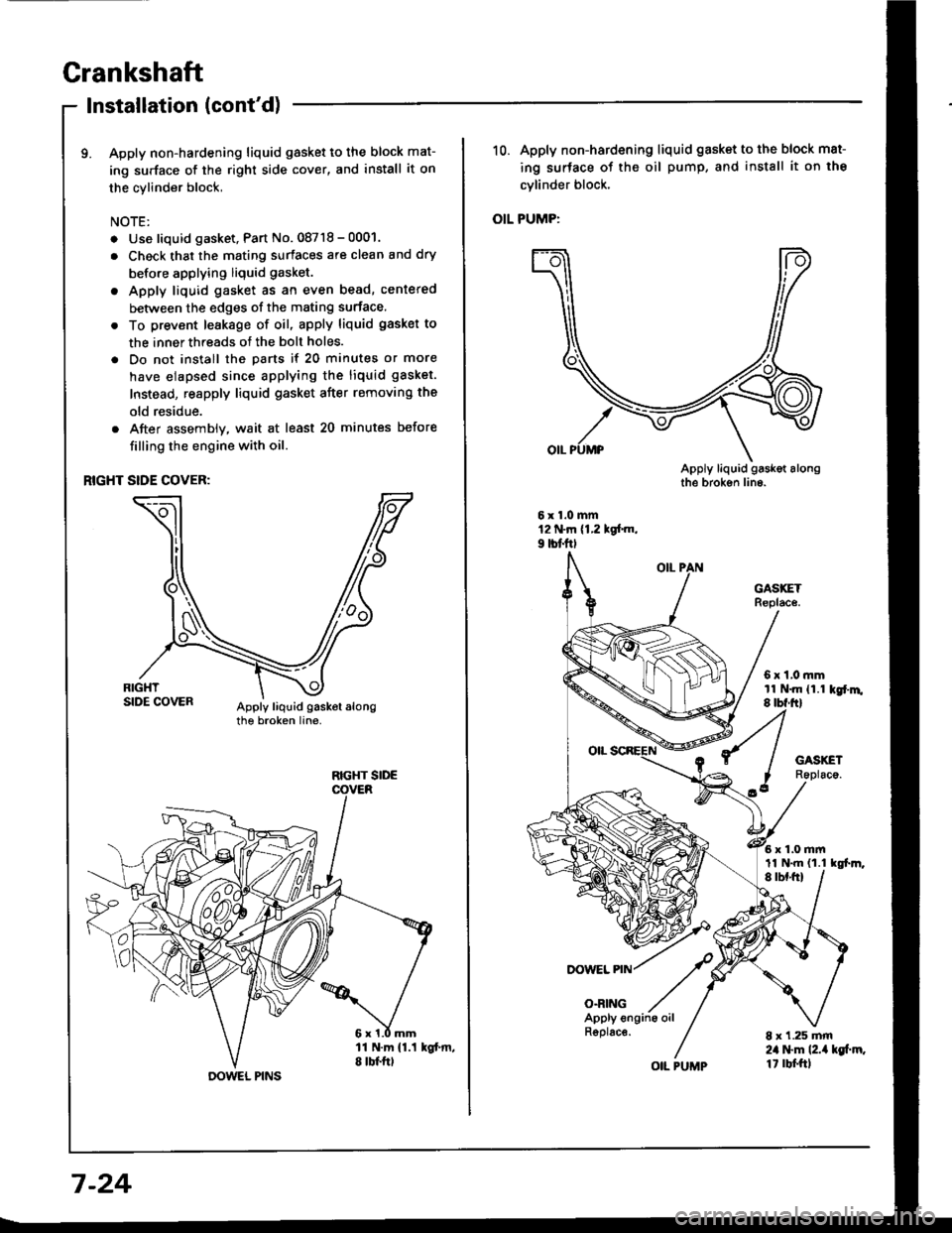
9. Apply non-hardening liquid gasket to the block mat-
ing surface of the right side cover, and install it on
the cylinder block,
NOTE:
. Use liquid gasket, Part No. 08718 - 0001.
. Check that the mating surfaces are clean and dry
before applying liquid gasket.
. Apply liquid gasket as an even bead, centered
between the edges of the mating surface.
. To prevent leakage of oil, apply liquid gasket to
the inner threads of the bolt holes.
. Do not install the parts if 20 minutes or more
have elapsed since applying the liquid gasket.
Instead, reapply liquid gasket after removing the
old residue.
. After assembly, wait at least 20 minutes before
filling the engine with oil.
RIGHT SIDE COVER:
RIGHT SIDE
DOWEL PINS
7-24
R6plac€.
OIL PUMP
10. Apply non-hardening liquid gasket to the block mat-
ing surface of the oil pump, and install it on the
cvlinder block.
OIL PUMP:
DOWEL PIN
O.RING
6x1,0mmtl N.m {1.1 kgr'm.8 tbf.ftl
6x1.0mm
8 x 1.25 mm2il l$m l2.ia kg[.m.1t rbf.ftl
11 N.m {1.1 tgl.m,
Page 166 of 1413
Installation (engine removal not
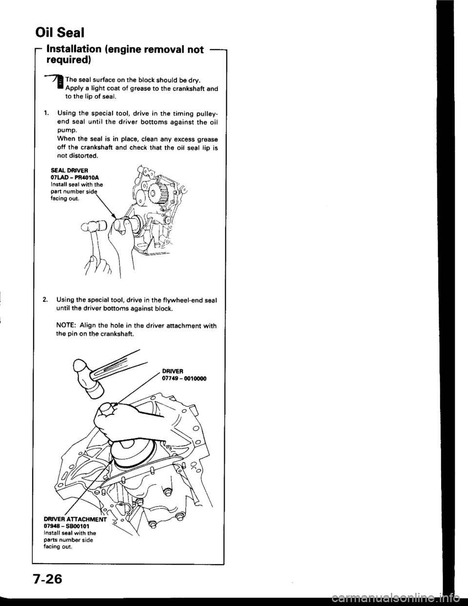
S€AL DRIVEB07LAD - PRimroAlnstallse6lwith tho
Pan numbertacing out.
Using the special tool, drive in the flywheel-end seal
until the driver bottoms against block.
NOTE: Align the hole in the drivsr attachment withthe Din on the crankshaft.
Oil Seal
required)
The seal surface on the block should b€ dry.Apply a light coat of grease to the crankshaft andto the lio of seal.
Using the special tool, drive in the timing pullsy-
end seal until the driver bottoms against the oilpump.
When the seal is in place, clean any excess grease
off lhe crankshaft and check that the oil seal tiD isnot distoned.
7-26
Page 171 of 1413
Engine Oil
lnspection
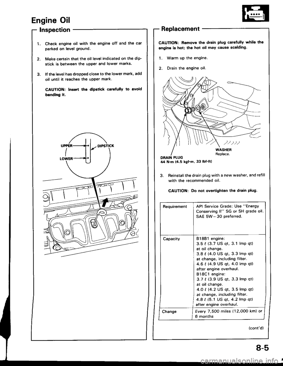
Check engine oil with the engine off and ths cal
parked on level ground,
Make cenain that the oil level indicated on the dip-
stick is between the upper and lower marks.
lf the l€vel has dropped close to the lower mark, add
oil until it reaches the upper mark.
CAUTION: Inssrt lho dipstick carotully to avoid
bending it.
3.
Replacement
CAUTION: Remova tho drain plug cal€fully whilo the
ongine is hot; the hot oil may cause scalding.
1. Warm up the engine.
2, Drain the engine oil.
3. Reinslallthe drain plug with a new washer, and refill
with the recommended oil.
CAUTION: Do not ovortighton tho drain plug.
(cont'd)
RequirementAPI Service Grade: Use "Energy
Conserving ll" SG or SH grade oil.
SAE 5W-3O Drefered.
CapacityB18B1 engine:
3.51 (3.7 US qt, 3.1 lmp qtl
at oil change.
3.8 t (4.0 US qt, 3.3 lmp qt)
at change. including filter.
4.6 I 14.9 US qt. 4.0 lmp qt)
after engine overhaul.
B18Cl engine:
3.7 f (3.9 US qt, 3.3 lmp qt)
at oil change.
4.O t 14.2 US qt, 3.5 lmp qt)
at change, including filter.
4.a I (5.1 US qt, 4.2 lmp qt)
after engine overhaul.
ChangeEvery 7,5OO miles (12,OOo km) or
6 months
8-5
Page 172 of 1413
Englne Oil
Replacement {cont'd)
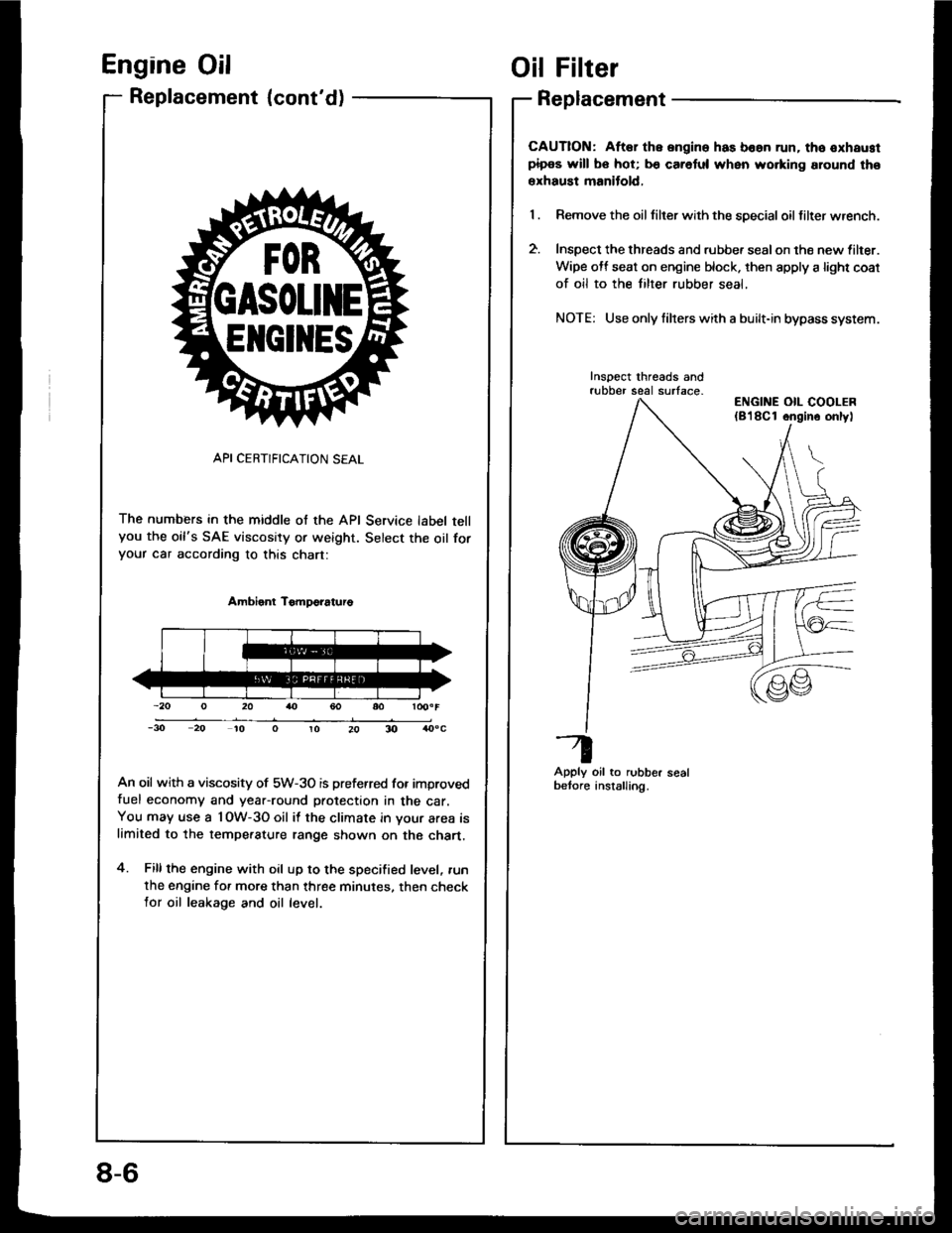
API CERTIFICATION SEAL
The numbers in the middle of the API Service label tellyou the oil's SAE viscosity or weight. Select the oil foryour car according to this chart:
Ambient TomDo?aturo
An oil with a viscosity of 5W-3O is preferred for improvedfuel economy and year-round protection in the car.You may use a l OW-3O oil it the climate in your area islimited to the tempe.ature range shown on the chart.
4. Fillthe engine with oil up to the specified level, .un
the engine for more than three minutes. then checklor oil leakage and oil level.
ElrclltEs
Oil Filter
Replacement
CAUTION: Aftar the ongine has boan run. tho oxhaustpipos will bo hot; b€ caretul when wo.king around tho
erhaust manitold,
Remove the oil tilter with the special oil filter wrench.
Inspect the threads and rubbe. sealon the new lilter.
Wipe off seat on engine block. then apply a light coat
of oil to the tilter rubber seal,
NOTE: Use only filrers with a built-in bypass system.
Inspect threads andrubber seal surface-
Apply oil to rubber sealbetore anstalling.
ENGINE OIL COOLER(8'l8Cl ongino onlyl
8-6
Page 173 of 1413
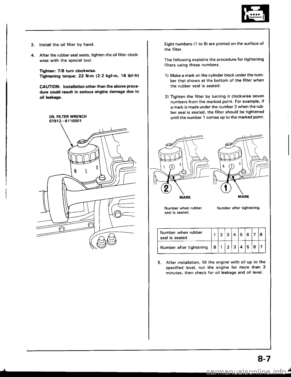
Install the oil tilter by hand.
After the rubber sesl seats, tighten the oil filter clock-
wise with the special tool.
Tighten: 7/8 turn clockwise.
Tightening torque: 22 N.m (2.2 kgf'm, 16 lbf'ft)
CAUTION: Installation other than the abova ploce-
dure could r6suh in serious engine damag€ due to
oil leakage.
OIL FILTEB WRENCH07912-6110001
4.
_l-
8-7
Eight numbers {'l to 8) are printed on the surface of
rhe filter.
The following explains the procedure for tightening
filters using these numbers.
1 ) Make a mark on the cvlinder block under the num-
ber that shows al the bottom of the filter when
the rubber seal is seated.
2) Tighten the tilter by turning it clockwise seven
numbers from the marked point. For example, if
a mark is made under the number 2 when the tub-
ber seal is seated. the filter should be tightened
until the number 'l comes up to the marked point.
Number when rubberseal is seated.Number after tightening.
MARK
Number when rubber
seal is seated46I
Number after tightening8?o7
5. After installation, till the engine with oil up to the
specified level, run the engine for more than 3
minutes, then check for oil leakage and oil level.
.41
Page 174 of 1413
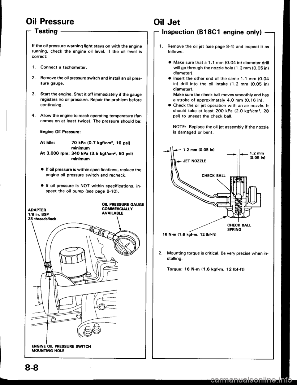
Oil Pressure
Testing
lf the oil pressure warning light stays on with the enginerunning, check the engine oil level. lf the oil level is
correct:
1. Connect a tachometer.
2. Remove the oil pressure switch and install an oil pres-
sure gauge.
3. Stan the engine. Shut it off immediately if the gauge
registers no oil pressure. Repair the problem before
continuing.
4. Allow the engine to reach operating temperatu,e {fancomes on at least twice). The Dressure should be:
Engine Oil Pressure:
At ldle: 70 kPa (0.7 kgf/cmr, 10 psi)
minimum
At 3,OOO lpm: 340 kPa {3.5 kgf/cmz, 50 psi}
minimum
a lJ oil pressure is within speciJications, replace the
engine oil pressure switch and recheck.
a lf oil pressure is NOT within specifications, in-
spect the oil pump (see page 8-1O).
1.2 mm 10.05 in)
'16 N.m (1.6 kgt.m, l2lbt.ftl
Oil Jet
Inspection (B18C1 engine only|
Remove the oil jet (see page 8-4) and inspect it as
follows.
a Make sure that a I .l mm (O.04 in) diameter drill
will go through the nozzle hole {1 .2 mm {O.OS in)
diameterl.
a Insert the other end of the same 1.1 mm (O.O4
in) drill into the oil intake {1.2 rnm {0.05 in}
diameter).
Make sure the check ball moves smoothlv and has
a stroke of approximately 4.0 mm {O. 16 in).a Check the oil jet operation with an air nozzle. lt
should take at least 2OO kPa (2.O kgf/cmr,28
Dsi) 10 unseat the check ball.
NOTE: Replace the oiljet assembly if the nozzle
is damaged or bent.
2. Mounting torque is critical. Be very precise when in-
stalling.
Torque: 16 N.m (1.6 kgt.m, 12lbf.ftl
OIL PRESSURE GAUGECOMMERCIALLYAVAILABI.E
8-8
Page 176 of 1413
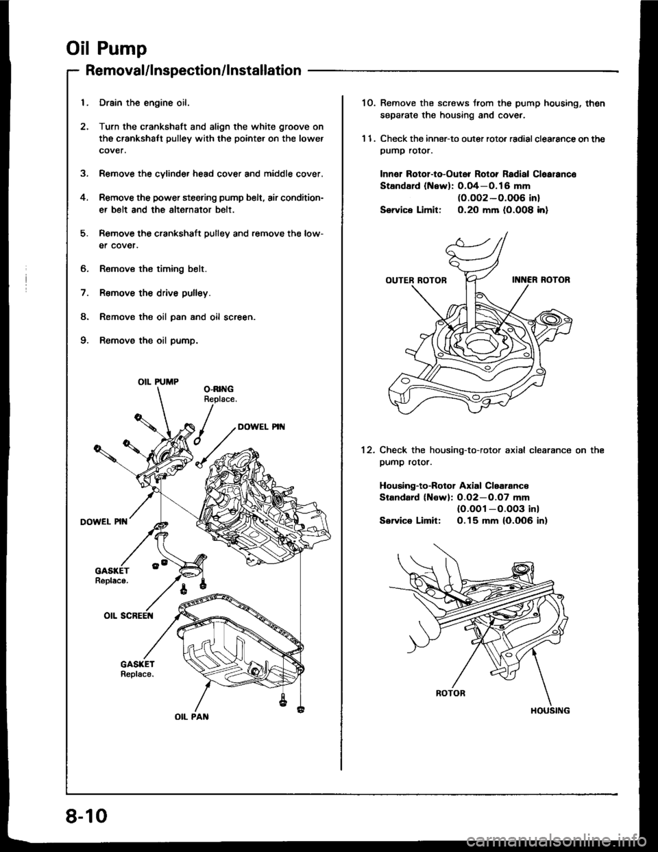
Oil Pump
5.
4.
Removal/lnspection/lnstallation
6. Remov€ the timing belt.
7. R€move the drive pulley.
8. Remov€ the oil pan and oil screen.
9. Remove the oil pump.
Drain the engine oil.
Turn the crankshatt and align the white groove on
the crankshalt pulley with the pointer on the lower
cover.
Remove the cylinder head cover and middle cover.
Remove the power steering pump belt, air condition-
er belt and the alternator belt.
Remove the crankshaft pulley and remove the low-
er cover.
OIL PUMP
OIL PAN
8-10
1O. Remove the screws trom the pump housing, thsn
separate the housing and coveJ.
1 1. Check the inner-to outer roto. radial clearance on thepumP rotor.
Innor Rotol-to-Outor Rotor Radial Cloaranco
StandErd (Newl: O.O4-O.16 mm(0.O02-0.006 in)
Service Limit: O.2O mm (0.008 inl
Check the housing-to-rotor axial clearance
pump rotor.
Housing-to-Botor Axial Claalanc€
Standard (Nowl: O.O2-O.O7 mm(O.OO1 -O.OO3 inl
Service Limit: O.15 mm (0.006 in)
on the12.
HOUSING
Page 177 of 1413
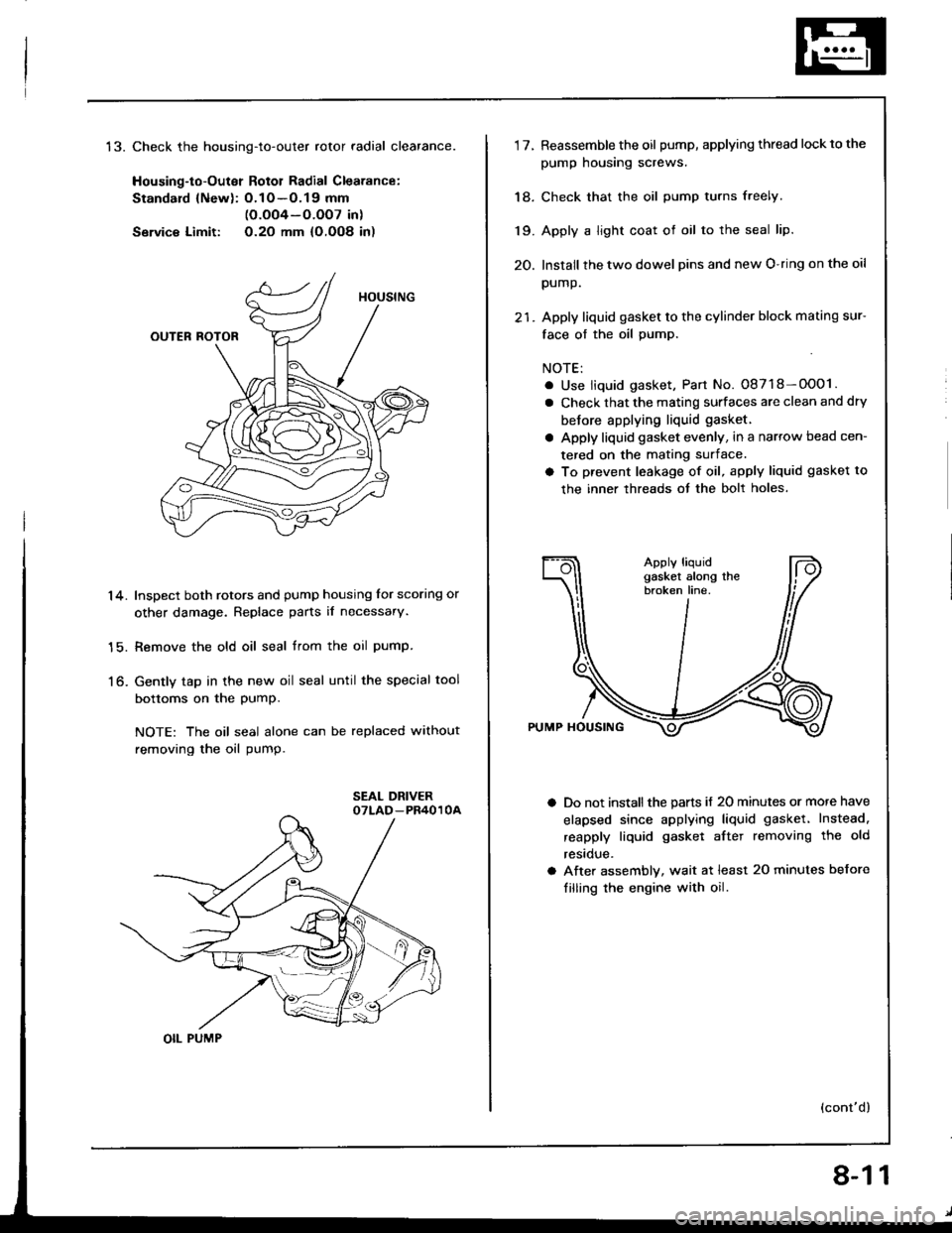
t5.Check the housing-to-outer rotor radial clearance.
Housing-to-Outer Rotol Radial Clearance:
Standard {Newl: O.1O -O.19 mm(O.oO4-O.OO7 in)
Servic€ Limit: O.2O mm {O,OO8 in)
Inspect both rotors and pump housing for scoring or
other damage. Replace parts il necessary.
Remove the old oil seal trom the oil pump.
Gently tap in the new oil seal until the special tool
bottoms on the PumP.
NOTE: The oil seal alone can be replaced without
removing the oil pump.
14.
15.
to-
OIL PUMP
8-11
1'lReassemble the oil pump, applying thread lockto the
pump housing screws.
Check that the oil pump turns freely.
Apply a light coat of oil to the seal lip.
Install the two dowel pins and new O-ring on the oil
pump.
Apply liquid gasket to the cylinder block mating sur-
face of the oil pump.
NOTE:
. Use liquid gasket, Part No. 08718-OOO1.
a Check that the mating surfaces are clean and dry
betore applying liquid gasket.
a Apply liquid gasket evenly, in a narrow bead cen-
tered on the mating surface.
a To prevent leakage of oil, apply liquid gasket to
the inner threads ot the bolt holes.
Do not install the parts if 20 minutes or more have
elapsed since applying liquid gasket. Instead.
reapply liquid gasket aftet removing the old
restclue.
After assembly, wait at least 20 minutes before
filling the engine with oil.
(cont'd)
18.
19.
20.
Page 178 of 1413
Oil Pump
DOWEL PINS
Removal/lnspection/lnstallation
(cont'd)
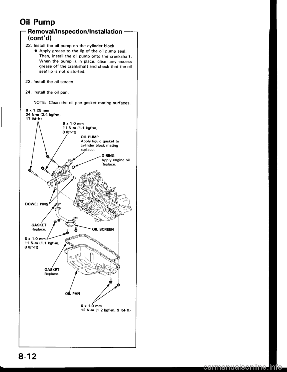
22. Install the oil pump on the cylinder block.a Apply grease to the lip of the oil pump seal.
Then, install the oil pump onto the crankshaft.
When the pump is in place, clean any excessgrease oll the crankshaft and check that the oil
seal lip is not distorted.
23. Install the oil screen.
24. Install the oil pan.
NOTE: Clean the oil pan gasket mating surtaces.
8 x 1.25 mm24 N.m (2.4 kgl.m,17 tbt.ftl
6 r 1.O mm1'l N.m {1.1 kgf.m,8 rbf.fr)
OIL PUMPApply liquid gasket tocylinder block matingsudace.
O-RINGApply engine oil
GASKETReplace.
6 x 1.O mm
OIL SCREEN
11 N.m ('l .1 kgf.m,8 tbf.trl
OIL PAN
6 x 1.O mm12 N.m {1.2 kgf.m, 9 lbf.ft}
8-12
Page 180 of 1413
Intake Manifold
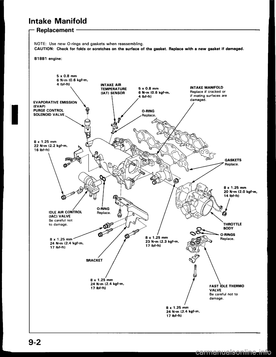
Replacement
NOTE: Use new O-rings and gaskets when reassembling.
CAUTION: Check for tolds or scratches on the aurface ot the gasket. Roplace with a now gasket it damagod,
81881 engine:
5r0.8mm6 N'm {0.6 kgl.m.4 rbr.ftlINTAKE AIRTEMPERATUREIIATI SENSOR
'*o*ot'u""'""N
5xO.8mm6 .m (0.6 kg{.m.4 tbf.ftl
O-RINGReplace.
IiITAKE MANIFOLDReplace iI cracked orit mating s!rtaces arodamag€o.
PURGE CONTROLSOLENOID VALVE
8 x 1.25 mm22 N.r 12.2 kgl.m,'16 tbt.ftt
IDLE AIR
GASKETSReplace.
I x 1.25 mm20 N.m (2.0 kgt.m.14 rbf.ftl
O.RINGReplace.{IACI VALVEBe careful notto damage.THROTTLE
8 x 1.25 mm
BODY
O-RINGSBeplace.
24 N.m (2.4 kgf'm,17 rbf.ft)
8 x 1.25 mm23 N.m (2.3 kgl.m,17 lbf.frl
BRACKET"o
aYc
g
/
1.25 mmN.m (2.4 kgl'm,rbf'ft1
8x2417
8 x 1.25 mm24 N.m (2.4 kgl'm.17 tbr.ftlTHERMOVALVE8e careful not todamage.
9-2