check engine HONDA INTEGRA 1994 4.G User Guide
[x] Cancel search | Manufacturer: HONDA, Model Year: 1994, Model line: INTEGRA, Model: HONDA INTEGRA 1994 4.GPages: 1413, PDF Size: 37.94 MB
Page 102 of 1413
WEC Solenoid Valve Inspection
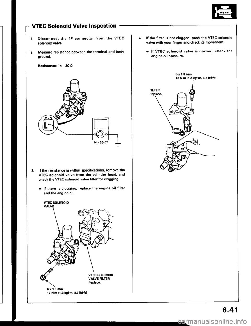
Disconnect the 1P connector trom the VTEC
solenoid valve.
M€asurs resistance between th€ terminal 8nd body
grouno.
R.3bt!nc!: 1l - 30 O
lf the resistance is within specificstions, romove the
WEC sol€noid valve from the cvlindor hsad, and
check the VTEC solenoid valve filter for clogging.
. lf there is clogging, replacs the engin€ oil filter
and the engine oil.
VTEC SOT.CNOTD
12 tTln 11.2 kg[.m,8.7 lbttt]
6-41
4. lf th6 filter is not clogged, push the VTEC solenoid
valv€ with your finger and check its movement.
. lf VTEC solsnoid valve is normal, check the
engins oil pr€ssure.
6x1.0mm
Page 139 of 1413
11.
12.
13.
Cylinder Head
Installation lcont'd)
lnstallthe timing belt lsee page 6-51).
Adjust the valve clearance (see page 6-44).
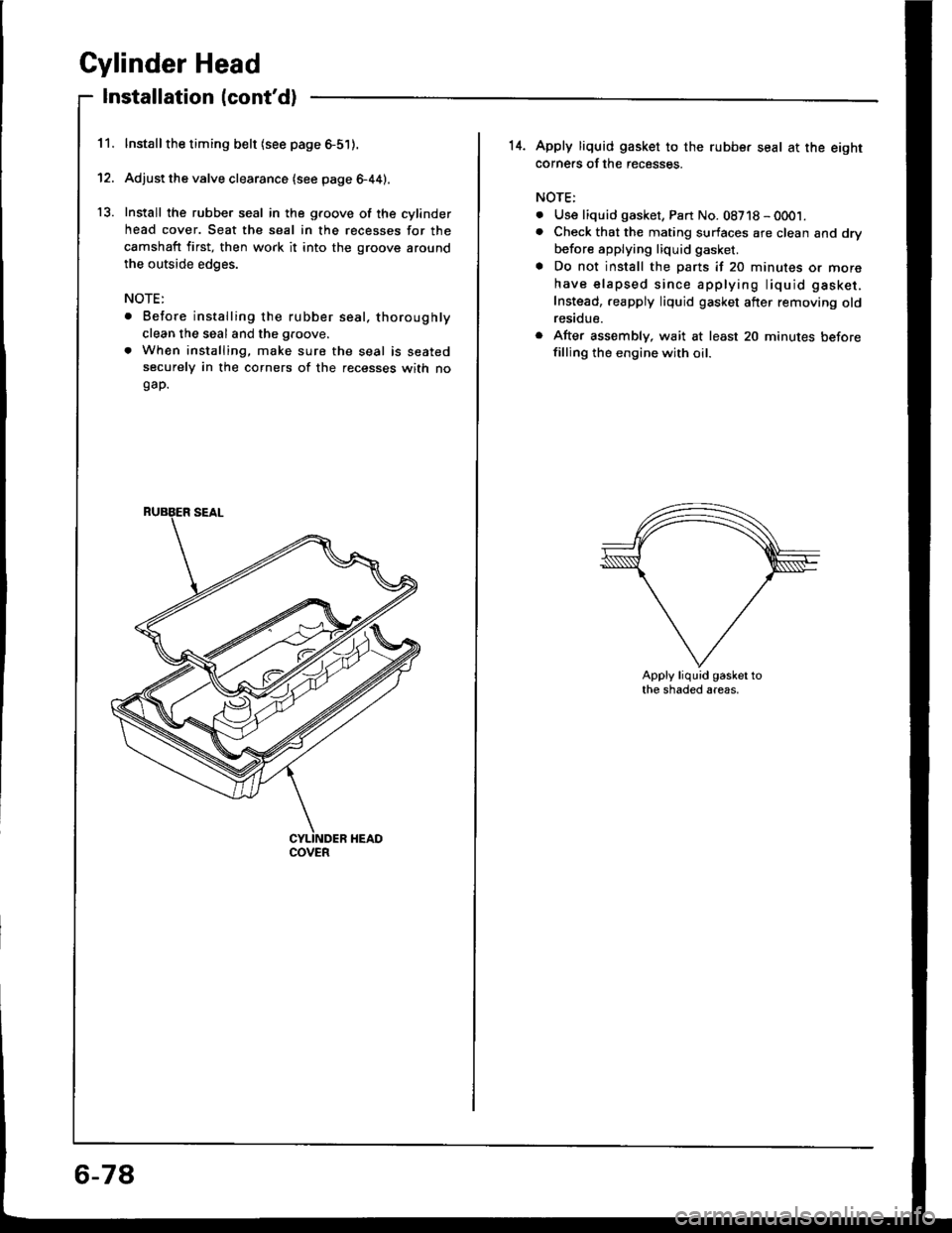
Install the rubber seal in the groove of the cylinder
head cover. Seat the seal in the recesses for the
camshaft first, then work it into the groove around
the outside edges.
NOTE:
. Before installing the rubber seal. thoroughly
clean the seal and the groove.
. When installing, make sure the seal is seatedsecurely in the corners of the recesses with nogap.
COVER
6-78
14. Apply liquid gasket to the rubbe. seal at the eightcorne.s of the recesses.
NOTE:
. Use liquid gasket, Part No. 08718 - 0001.. Check that the mating surfaces are clean and dry
before applying liquid gasket.
a Do not install the parts if 20 minutes or more
have elapsed since applying liquid gasket.
Instead,.eapply liquid gasket after removing oldresidue.
r After assembly, wait at least 20 minutes beforefilling the engine with oil.
Apply liquid gasket tothe shaded areas.
Page 143 of 1413
lllustrated Index
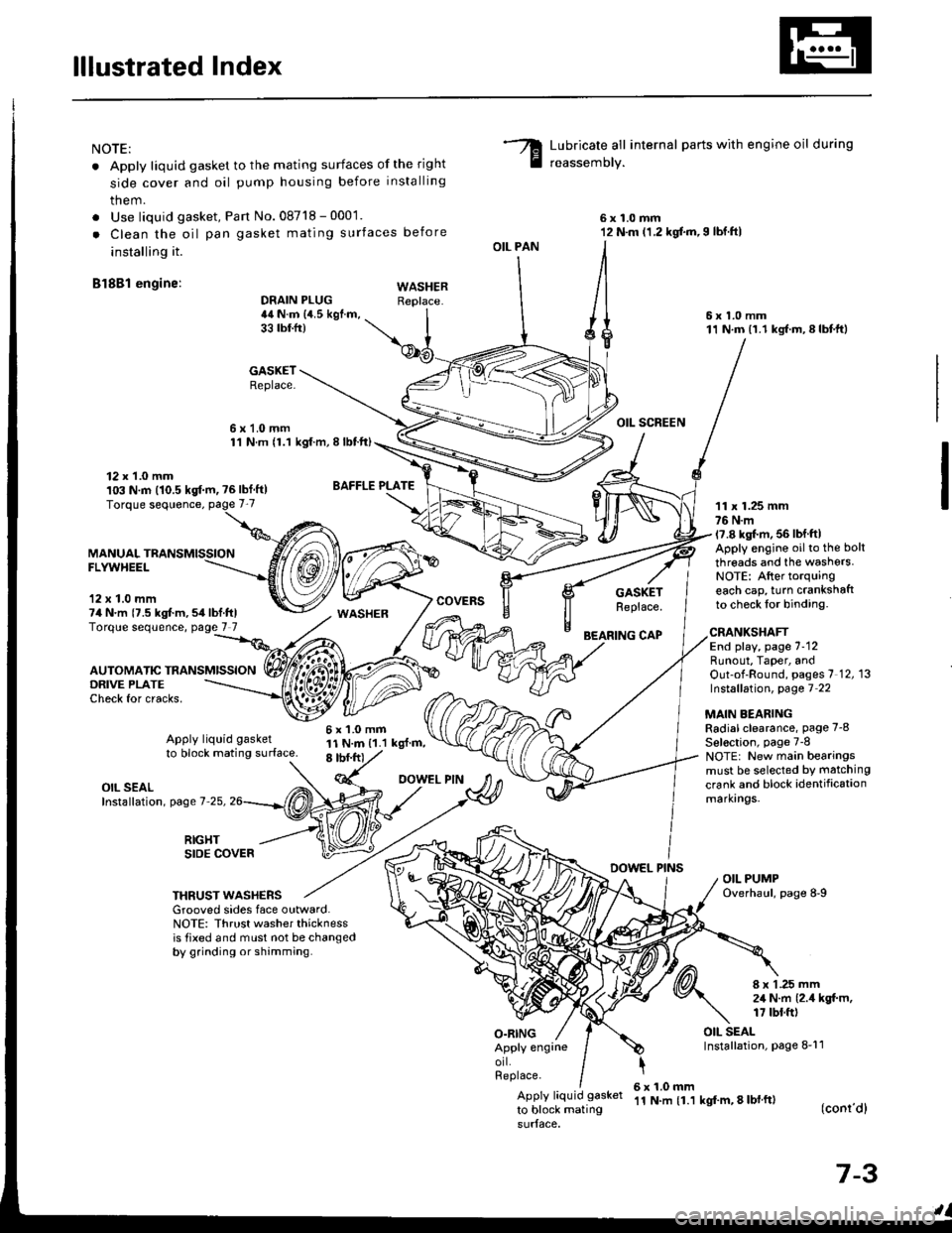
NOTE:
. Apply liquid gasket to the mating surfaces of the right
side cover and oil pump housing before installing
them.
. Use liquid gasket, Pan No.08718 - 0001.
. Clean the oil pan gasket mating surfaces before
installing it.
Bl8Bl engine: wAsHEF
Lubricate all internal parts with engine oil during
reassemory.
6x1.0mm12 N.m (1.2 kgf.m,I lbf.ftl
6x1.0mm11 N.m (1.1 kgf.m,8lbtft)
OIL SCREEN
11 x 1.25 mm76 N.m17.8 kgl.m, 56 lbf ftlApply engine oilto the bolt
threads and the washers.NOTE: After torquingeach cap, turn crankshaftto check lor binding.
DRAIN PLUG44 N.m {4.5 kgf.m,33 tbtfr)
GASKETReplace.
6x1.0mm1'l N.m {1.1 kgt.m, I lbtft)
OIL PAN
O.RING
GASKETReplace.
BEARING CAP
12 x 1.0 mm103 N.m (10.5 kgf.m, ?6lbf ft)
MANUALFLYWHEEL
'12 x 1.0 mm74 N.m {7.5 kgt m,54lbf.ftlTorque sequence, page 7 7
DRIVE PLATECheck for cracks,
AUTOMATIC TRANSMISSION
WASHER
6x1.0mm11 N.m {1.1 kgl.m,8 tbf.frt
CRANKSHAFTEnd play, page 7-12Runout, Taper, andOut-of-Round, pages 7 12, 13Instsllation, page 7 22
MAIN BEARINGRadial clearance, page 7-8
Sel€ction, page 7-8NOTE: New main bearingsmust be selected by matching
crank and block identificationmarkrngs.
Apply liquid gasket
to block mating surface.
OIL SEALInstallation, page 7-25,
RIGHTSIDE COVERDOWEL PINSOIL PUMPOverhaul, page 8-9THRUST WASHERSGrooved sides face outward.NOTE: Thrust washer thicknessis tixed and must not be changedby grinding or shamming.
8 x 1 .25 mm2,1 N.m {2.4 kgt m,17 tbt.ft)
OIL SEALInstallation, page 8-11Apply engrneorl.Replace.
Apply liquid gasket
to block mating
6x1.0mm'11 N.m {1.1 kgf'm, 8 lbl ft)(conr'dl
7-3
Page 145 of 1413
BEARINGCAP BRIDGE
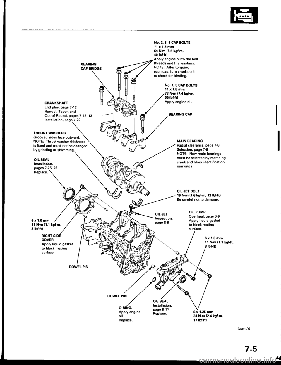
No. a 3, /a CAP BOLTSll x 1.5 mm64 N.m {6.5 kgt m,49 tbf.ftlApply engine oilto tho boltthreads and the washers.NOTE: Aftertorquingeach cap, turn crankshaftto check for binding.
No. 1,5 CAP BOI-TS11 x 1.5 mm73 N.m {7.4 kgf.m,56 tbt'ft|Apply engine oil.
BEARING CAP
CRANKSHAFTEnd play, page 7-12Runout, Taper, andOut-of-Round, pages 7'12. 13Installation, page 7-22
YHRUST WASHERSGrooved sides lace outward.NOTE: Thrust washer thicknessis fixed and must not be chano€d
MAIN BEARINGRadial clearance. page 7 8S6l€ction, page 7-8NOTE: New main bearingsmust be selected by matchingcrank and block identificationmarxrngs.
OIL JEI BOLY16 N.m 11.6 kg{'m, 12lbtftlBe caretul not to damage.
OIL PUMPOverhaul, page 8-9Apply liquid gasket
to block matingsurface.
OIL SEALInstallation,pages 7-25, 26
11 N.m 11.1 kgt m,8 lbf ftl
Replace.
6r1.0mm
OIL JETInspection,page 8-8
OIL SEALInstellelion,page 8-11Replace.
RIGHT SIDECOVERApply liquid gasketto block matingsurface.
6x1.0mm11 N.m {1.18 rbf.ftlkSf.ft,
DOWEL PIN
DOWEL PIN
O.RING.Apply engineorl.Replace.
8 x 1.25 mm24 N.m {2.4 kgt m,17 tbtft)
(cont'd)
7-5
Page 146 of 1413
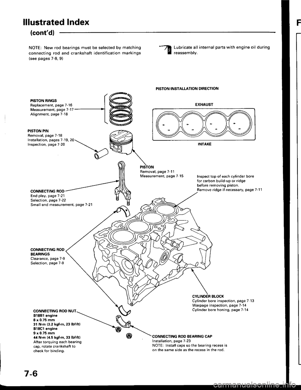
lllustrated IndexF
(cont'd)
NOTE: New rod bearings must be selected by
connecting rod and crankshaft identification
(see pages 7-8,9)
matching
marKrngs
Lubricate all internal parts with engine oil during
reassemorv.
PISTON RINGSReplacement, page 7'16Measurement. page 7-17Alignment, page 7 18
PISTON PINRemoval, page 7-18lnstallation, pages 7 19, 20Inspection, page 7'20
PISTON INSTALLATION DIRECTION
EXHAUST
INTAKE
Removal, page 7'11Measurement, page 7 15Inspect top of each cylinder borefor carbon build-up or ridgobetore removing piston.Remove ridge it necessary, page 7'11CONNECTING ROOEnd play, page 7-21
CONNECTING RODEEARINGSClearance, page 7-9Selection, page 7-9
CONNECTING ROD NUT818B1 ongine8x 0.75 mm31 N.m {3.2 kgf.m,23 lbf ftl818C1 engine9 x 0.75 mma,a N.m (4.5 kgt m, 33 lbf.ft|After torquing each bearangcap, rotate crankshaft tocheck for binding.
r-(,
Selection, page 7-22Small end measurement. page 7-21
BLOCXCylinder bore inspection, page 7 13Warpage inspection, page 7'14Cylinder bore honing, page 7-14
CONNECTING ROD BEARING CAPInstallation, page 7'23NOTE: Install caps so the bearing recess ison the same side as the recess in the rod.
r@
-1@
Page 148 of 1413
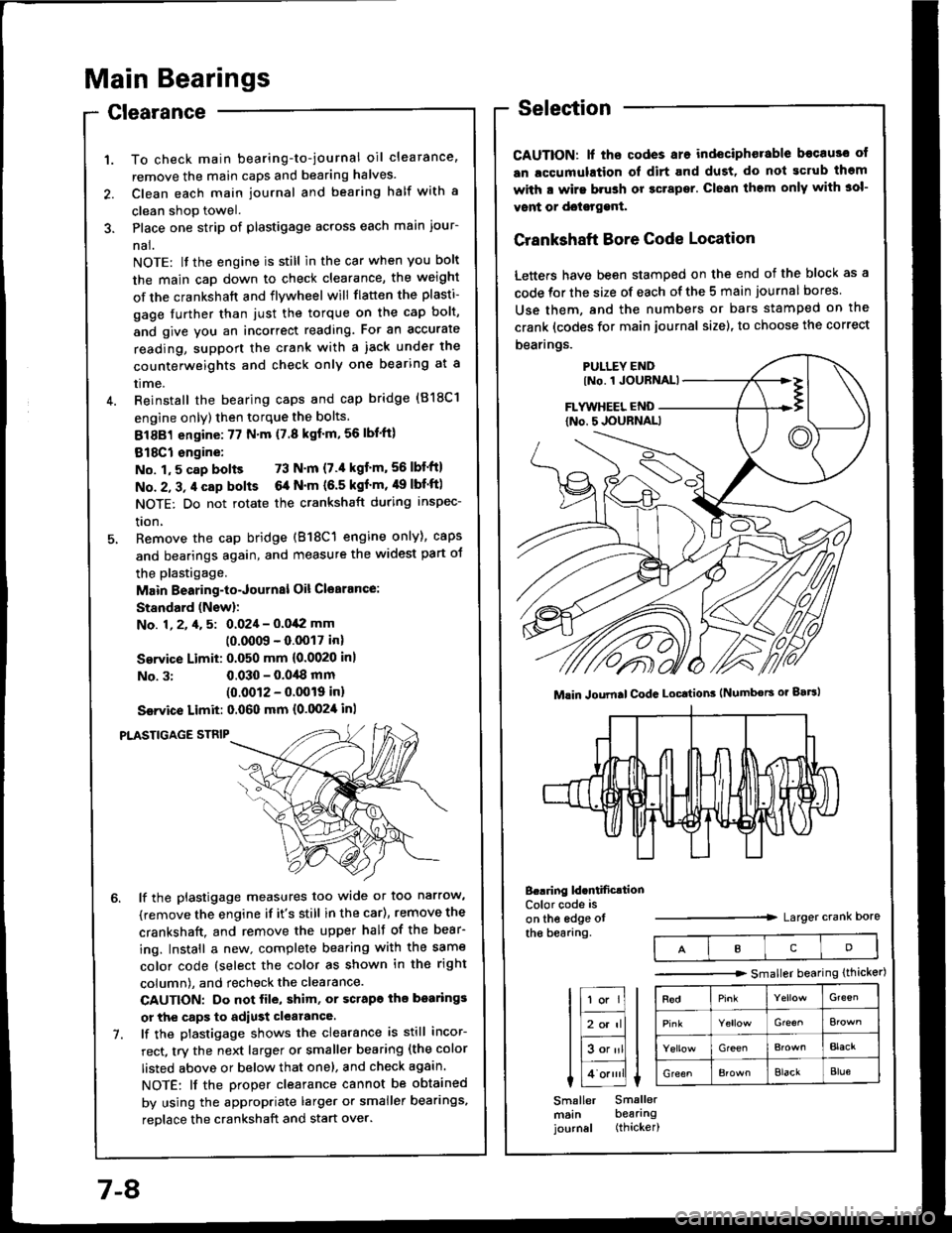
Main Bearings
Clearance
To check main bearing-to-journal oil clearance,
remove the main caps and bearing halves.
Clean each main journal and bearing half with a
clean shop towel.
Place one strip of plastigage across each main iour-
nal.
NOTE: lf the engine is still in the car when you bolt
the main caD down to check clearance, the weight
of the crankshaft and flywheel will flatten the plasti-
gage further than just the torque on the cap bolt,
and give you an incorrect reading. Fot an accurate
reading, support the crank with a iack under the
counterweights and check only one bearing at a
trme.
Reinstall the bearing caps and cap bridge (818C1
engine only) then torque the bolts.
81881 engine:77 N'm (7.8 kgf'm,56lbl'ft)
818C1 engine:
No. 1,5 cap bolts 73 N'm (7.'l kgt'm,56lbf'ftl
No. 2, 3, 4 cap bolts 6a N'm (6.5 kgf'm, 49 lbf'ftl
NOTE: Do not rotate the crankshaft during inspec-
tron,
Remove the cap bridge (818C1 engine only), caps
and bearings again, and measure the widest part oJ
the plastigage.
Main Bearing-to-Journal Oil Cl€arance:
Standard (Newl:
No. 1, 2, 4, 5: 0.024 - 0.042 mm
10.0009 - 0.0017 inl
Service Limit: 0.050 mm {0.0020 inl
No. 3:0.030 - 0.0,18 mm(0.0012 - 0.0019 inl
Ssrvice Limit: 0.060 mm {0.0024 inl
PLASTIGAGE STNIP
lf the plastigage measures too wide or too narrow,
(remove the engine if it's still in the car), remove the
crankshaft. and remove the upper half of the bear-
ing. Install a new. complete bearing with the same
color code (select the color as shown in the right
column), and recheck the clearance.
CAUTION: Do not file, shim, or scrapo ihe bo.rings
or the caps to adiust clearance.
lf the plastigage shows the clearance is still incor-
rect, try the next larger or smaller bearing (the color
listed above or below that one), and check again.
NOTE: lf the Droper clearance cannot be obtained
by using the appropriate larger or smaller bearings,
reolace the crankshaft and start over.
Selection
CAUTION: lf ths codes are indeciphorable becau3o ot
an lccumulation ol dirt and dust, do not gcrub thgm
with a wirs brush or gcrapsr. Clean them only with 3ol-
vont or doisrggnt.
Crankshaft Bore Code Location
Letters have been stamped on the end of the block as a
code for the size of each of the 5 main journal bores
Use them, and the numbers or bars stamped on the
crank (codes for main journal size), to choose the correct
bearings.
B..ring ld.ntificrtionColor code is
on the edge otthe bearang.Larger crank Dore
Mlin Joumal CodG Locttion3 (Numbors or gaBl
IcD
tr;;lIl
Itr-tl
lE;tl I tlHlt
I Lo.""li L
Smaller Smallermsin bearingjournal (thicker)
-------.r> smaller bearing (thicker)
G'een
Gre€^
GreenBlacr
GreenElackBlue
7-8
Page 154 of 1413
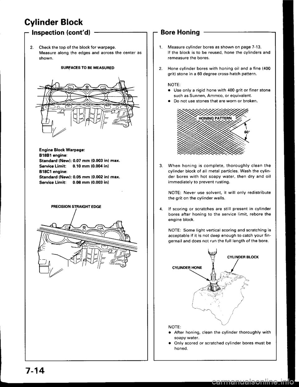
Cylinder Block
Inspection (cont'dl
2.Check the top of the block for warpage.
Measure along the edges and across the center as
snown.
SURFACES TO BE MEASURED
Engine Block Warpsgc:
81881 ongine:
Standard lNewl: 0.07 mm {0.003 inl max.
Service Limil: 0.10 mm {0.00,1inl
B18Cl engine:
Standard (New): 0.05 mm 10.002 inl max.
Service Limit 0.08 mm {0.003 inl
Measure cylinder bores as shown on page 7-13.
lf the block is to be reused, hone the cylinders and
remeasure the bores.
Hone cylinder bores with honing oil and a fine (400
grit) stone in a 60 degree cross-hatch pattern.
NOTE:
. Use only a rigid hone with 400 grit or finer stone
such as Sunnen, Ammco, or equivalent.
a Do not use stones that are worn or broken.
When honing is complete, thoroughly clean the
cylinder block of all metal panicles. Wash the cylin-
der bores with hot soapy water, then dry and oil
immediately to prevent rusting.
NOTE: Never use solvent, it will only redistribute
the grit on the cylinder walls.
lf scoring or scralches are still present in cylinder
bores after honing to the service limit, rebore the
engine block.
NOTEr Some light venical scoring and scratching is
acceptable if it is not deep enough to catch your fin-
gernail and does not run the full length of the bore.
CYLINDER HONE
. After honing, clean the cylinder thoroughly with
soapy water.
. Only scored or scratched cylinder bores must be
noneo.
7-14
Page 156 of 1413
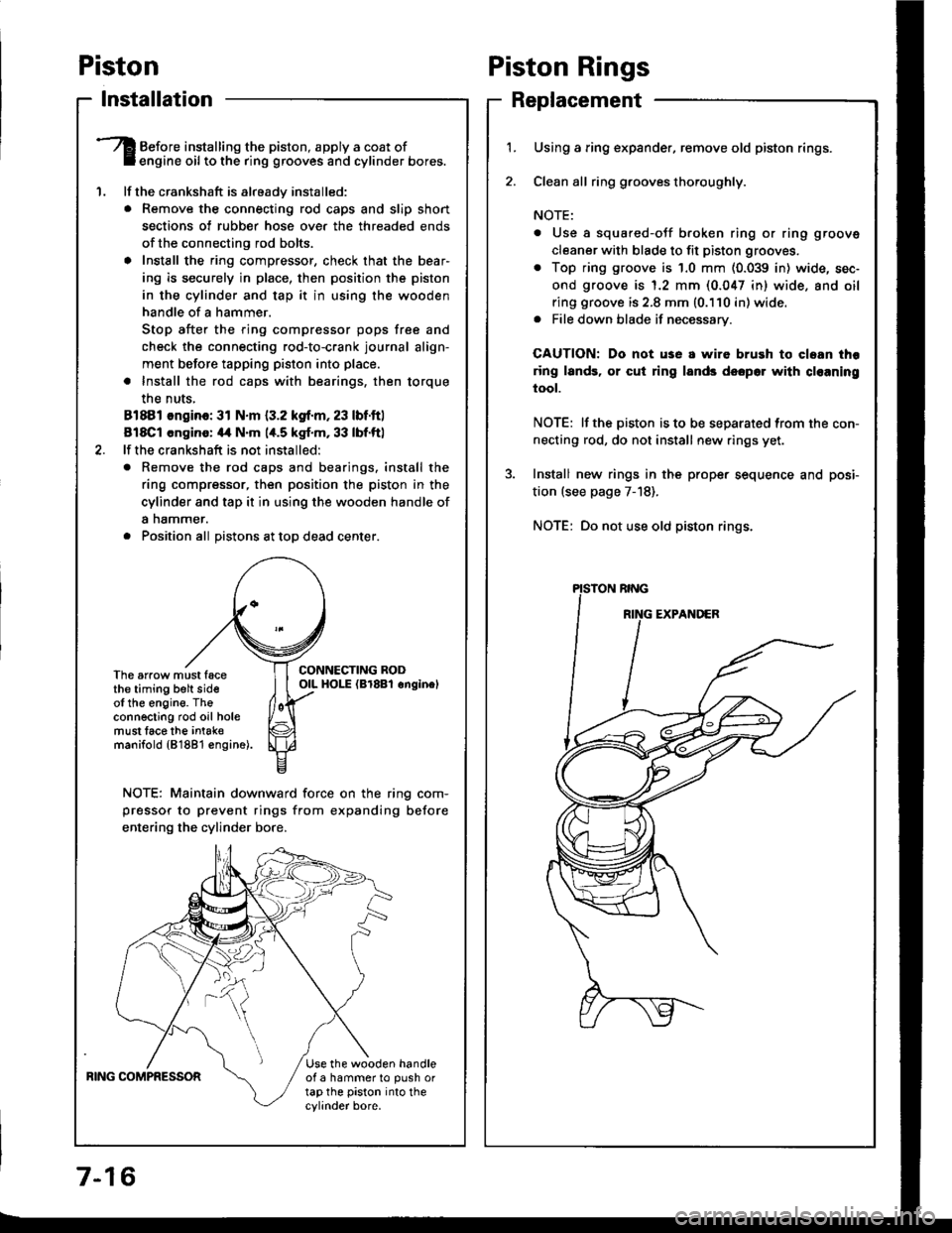
Piston
lnstallation
'1.
Before installing the piston, apply a coat ofengine oil to the ring grooves and cylinder bores.
lf the crankshaft is already installed:
. Remove the connecting rod caps and slip short
sections of rubber hose ove. the threaded ends
of the connecting rod bolts.
a Install the ring compressor, check that the bear'
ing is securely in place, then position the piston
in the cylinder and tap it in using the wooden
handle of a hammer.
Stop after the ring compressor pops free and
check the connecting rod-to-crank journal align-
ment before tapping piston into place.
. Install the rod caps with bearings, then torque
the nuts,
81881 ongino: 31 N.m {3.2 kgf.m, 23 lbf.ftl
818C1 cngino: 44 N'm 1,t.5 kgf.m, 33 lbf.ftl
lf the crankshaft is not installed:
o Remove the rod caps and bearings. install the
ring compressor, then position the piston in the
cylinder and tap it in using the wooden handle of
a nammer.
. Position all Distons at toD dead center.
CONNECTING RODOIL HOI-E (Br8Bl onginelThe arrow must facethe timing belt sideof the engine. Theconnecting rod oil holemust lace the intak€manifold {81881 €ngine).
NOTE: Maintain downward force on the ring com-
pressor to prevent rings from expanding before
entering the cylinder bore,
BING COMPRESSORUse the wooden handleof a hammer to push ortap the piston into thecylinder bore.
Piston Rings
Replacement
1.Using a ring expander, remove old piston rings.
Clean all ring g.ooves thoroughly.
NOTE:
. Use a squared-oJf broken ring or ring groove
cleaner with blade to fit piston grooves.
. Top ring groove is 1.0 mm (0.039 in) wide, sec-
ond groove is 1.2 mm (0.047 in) wide. and oil
ring groove is 2.8 mm (0.110 in) wide.. File down blade if necessary.
CAUTION: Do not use a wire brush to cloan thr
ring lands, or cut ring lands dsopo. with cl€aning
tool.
NOTE: lf the piston is to be separated from the con-
necting rod, do not install new rings yet.
Install new rings in the prope. sequence and posi-
tion (see page 7-18).
NOTE: Do not use old piston rings.
Page 157 of 1413
I
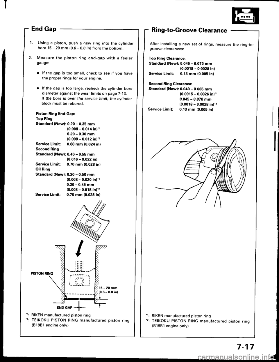
'1. Using a piston, push a new ring into the cylinderbore 15 - 20 mm (0.6 0.8 in) from the boftom.
Measure the piston ring end-gap with a feelergauge:
lf the gap is too small. check to see if you have
the proper rings for your engine.
lf the gap is too large, recheck the cylinder bore
diameter against the wear limits on page 7-13.
ll the bore is over the service limit, the cylinder
block must be rebored.
Piston Ring End-cap:
Top Ring
Standard (New): 0.20 - 0.35 mm(0.008 - 0.01'l inl'1
0.20 - 0.30 mm
10.008 - 0.012 inl''
Servica Limit: 0.60 mm (0.024 in)
Second Ring
Standard (Now): 0.40 - 0.55 mm
10.016 - 0.022 in)
Service Limit: 0.70 mm (0.028 in)
Oil Ring
Standard (New): 0.20 - 0.50 mm(0.008 - 0.020 in)'1
0.20 - 0.,15 mm
{0.008 - 0.018 inl',
Servica Limit: 0.70 mm 10.028 in)
After installing a new set of rings, measure the ring-to-gfoove clearances:
Top Ring Cl€arance:
Standard lNewl: 0.045 - 0.070 mm
10.0018 - 0.0028 in)
Service Limit: 0.13 mm {0.005 inl
Second Ring Clearance:
Standard {Newl: 0.040 - 0.065 mm(0.0015 - 0.0026 inl'1
0.0i15 - 0.070 mm(0.0018 - 0.0028 in)',
Service Limit: 0.13 mm (0.005 inl
iliiii.--r.llli.j- --.-PISTON NING
ioi
---'z llEND GAP -11--
RIKEN manufactured piston ring
TEIKOKU PISTON RING manufactured oiston rinq
{81881 engine only)
RIKEN manufactured piston ring
TEIKOKU PISTON RING manufactured Diston rino(B'1881 engine only)
7-17
Page 163 of 1413
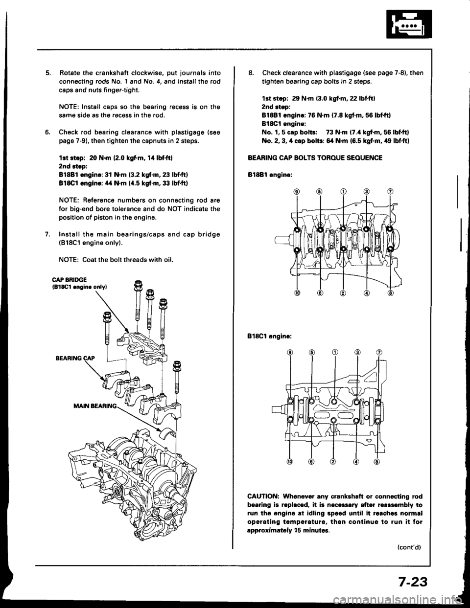
Rotate the crankshaft clockwise, put journals into
connecting rods No. 1 and No. 4, and install the rod
caps and nuts finge.-tight.
NOTE: lnstall caps so the bearing recess is on the
samg side as the .ecess in the rod.
Check rod bearing clsarance with plastigage (see
page 7-9), then tighten the capnuts in 2 steps.
l3t 3t.p: 20 N.m (2.0 kgf.m, rl btfil
2nd 3tep:
81881 cnginc: 31 N.m (3.2 kgf.m, 23 lbf.ft)
818C1 .ngin!: ,14 N.m (4.5 kgt.m,33 lbf.ft)
NOTE: Reference numbers on connecting rod are
for big-end bore tolorance and do NOT indicate the
positioo of piston in the engine.
Install the main bearings/caps and cap b.idge(818C1 engine onlyl.
NOTE: Coat the bolt threads with oil.
CAP BRIDGElBlSCl .noin. onlyl
EEARIlTG
8. Check clearsnce with plastigsge (see page 7-8). then
tighten bearing cap bolts in 2 steps.
13t st.p: 29 N.m (3.0 kgf.m, 22 lbt.ftl
2nd 3tsp:
81881 .ngin.: 76 N.m (7.8 kgt.m,56 lbf,ft)
Bl8Ct engine:
No. 1, 5 cap bol$: 73 N.m (7./r kgf'm, 56 lbf,ftl
No. 2, 3, a clp bolbr 6{ N.m (6.5 kgf'm, /r9 lbf,ftl
BEARING CAP BOLTS TOROUE SEOUENCE
Bl88l cngino:
Bl8Cl ongino:
CAUTION: Whenever any crsnkehaft or connocting rod
b.aring is rlphccd. it i5 ncccrsrry aftor rclssombly to
run tho ongino ai idling 3p6ad until it re.chei normrl
opcrating tcmporature, thon continuo to run it fol
spp.oximltoly f 5 minula3.
(cont'd)
7-23