connector HONDA INTEGRA 1994 4.G Owner's Manual
[x] Cancel search | Manufacturer: HONDA, Model Year: 1994, Model line: INTEGRA, Model: HONDA INTEGRA 1994 4.GPages: 1413, PDF Size: 37.94 MB
Page 218 of 1413
![HONDA INTEGRA 1994 4.G Owners Manual System Description
System Connectors [Dash and Floor] {contd}
UNDER-DASHFUSE/RELAYBOX
DASHBOARDHARNESS
MAINWIREHARNESS
11-26 HONDA INTEGRA 1994 4.G Owners Manual System Description
System Connectors [Dash and Floor] {contd}
UNDER-DASHFUSE/RELAYBOX
DASHBOARDHARNESS
MAINWIREHARNESS
11-26](/img/13/6067/w960_6067-217.png)
System Description
System Connectors [Dash and Floor] {cont'd}
UNDER-DASHFUSE/RELAYBOX
DASHBOARDHARNESS
MAINWIREHARNESS
11-26
Page 219 of 1413
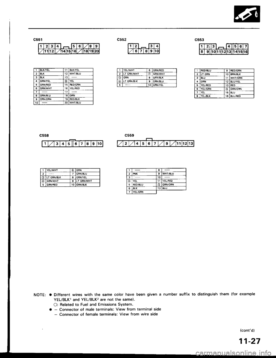
123467
Ir0l1 11121131 114115116
gL&YELBLK/YEL212BLKGFN,YELYEL515
I
6
GFNLT GRII/SL(9GRN/BLII5
REO/6LU28RN/8LK3BLU12BLUf/€LYEL/RED136YEL16BLUYEL/6LKt6
a DiJterent wires with the same color have been given a number sutfix to distinguish them (for example
YEL/BLK1 and YEL/BLK'� are not the same).
O: Related to Fuel and Emissions System.
a - Connector ot male terminals: View from terminal side- Connector of female terminals: View from wire side
{cont'd)
11-27
Page 220 of 1413
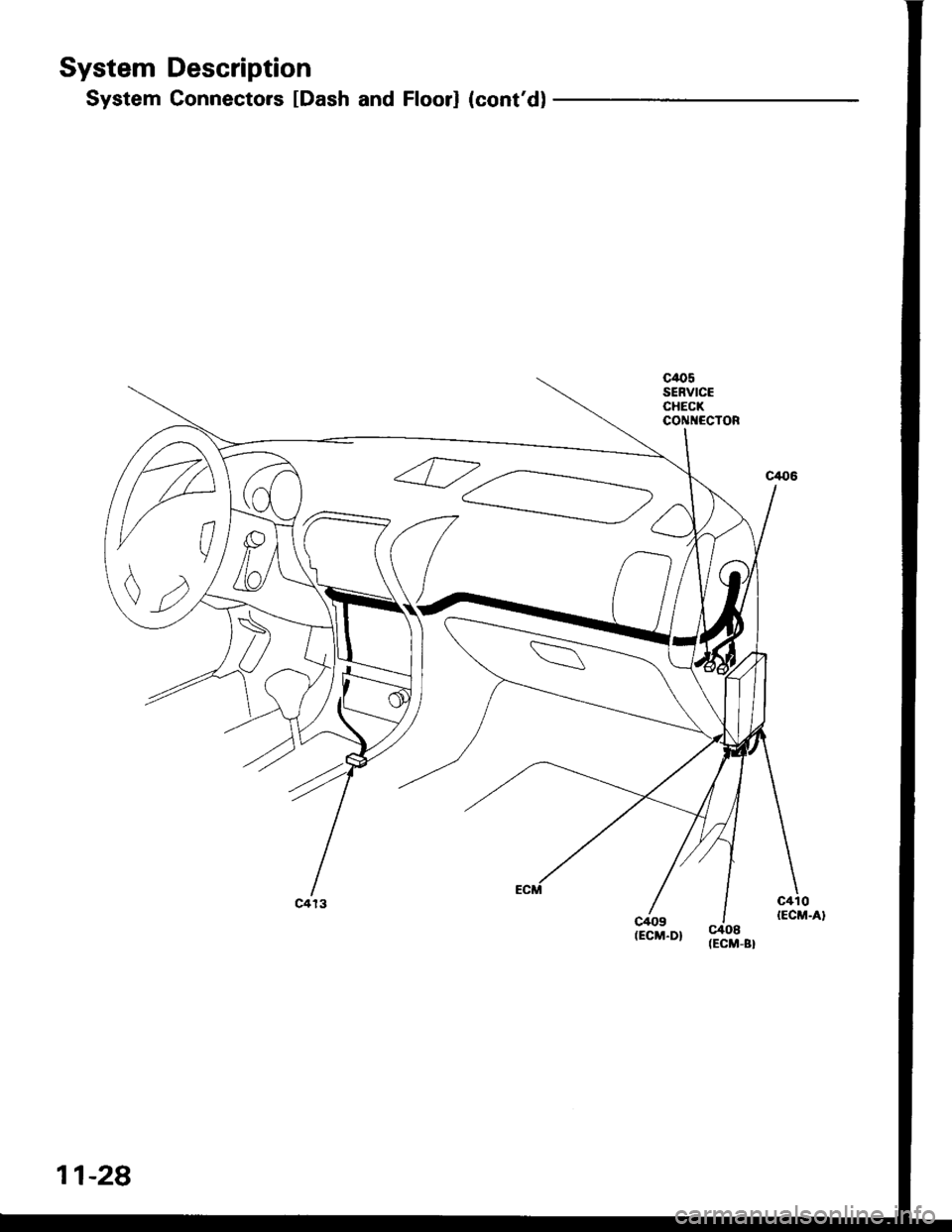
System Description
System Connectors [Dash and Floorl (cont'd)
c/ro5SERVICECHECKCONI{ECTOR
11-28
Page 221 of 1413
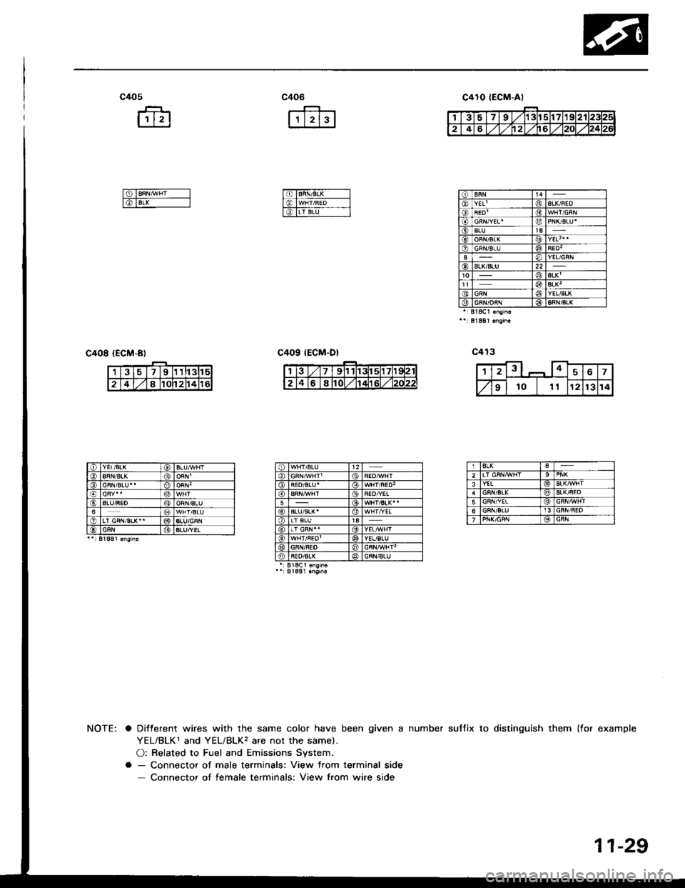
c405
fr
ffi
c406
r'tr--Jl
I6TBRN/B,L( -----l
l€, lwHr/uED -__-l
l6TLr BN--- l_l
c408 {ECM-Bl
suffix to distinguish them (for examplea Different wires with the same color have been given a number
YEL/BLK1 and YEL/BLK, are not the same).
O: Related to Fuel and Emissions System.
a - Connector of male terminals: View from terminal side
Connector of female terminals: View from wire side
c410 tEGM-Al
tt4YEL'| (jtALK/AED
SLU1aALKt(9YEL| 0o)
ALK'ALK'YEL/BLKGRN/oRr l@BLK
391t3tl5
2481Cl24
IALU/REO6
ALU/YEL
BLK2YEL
56
11-29
Page 222 of 1413
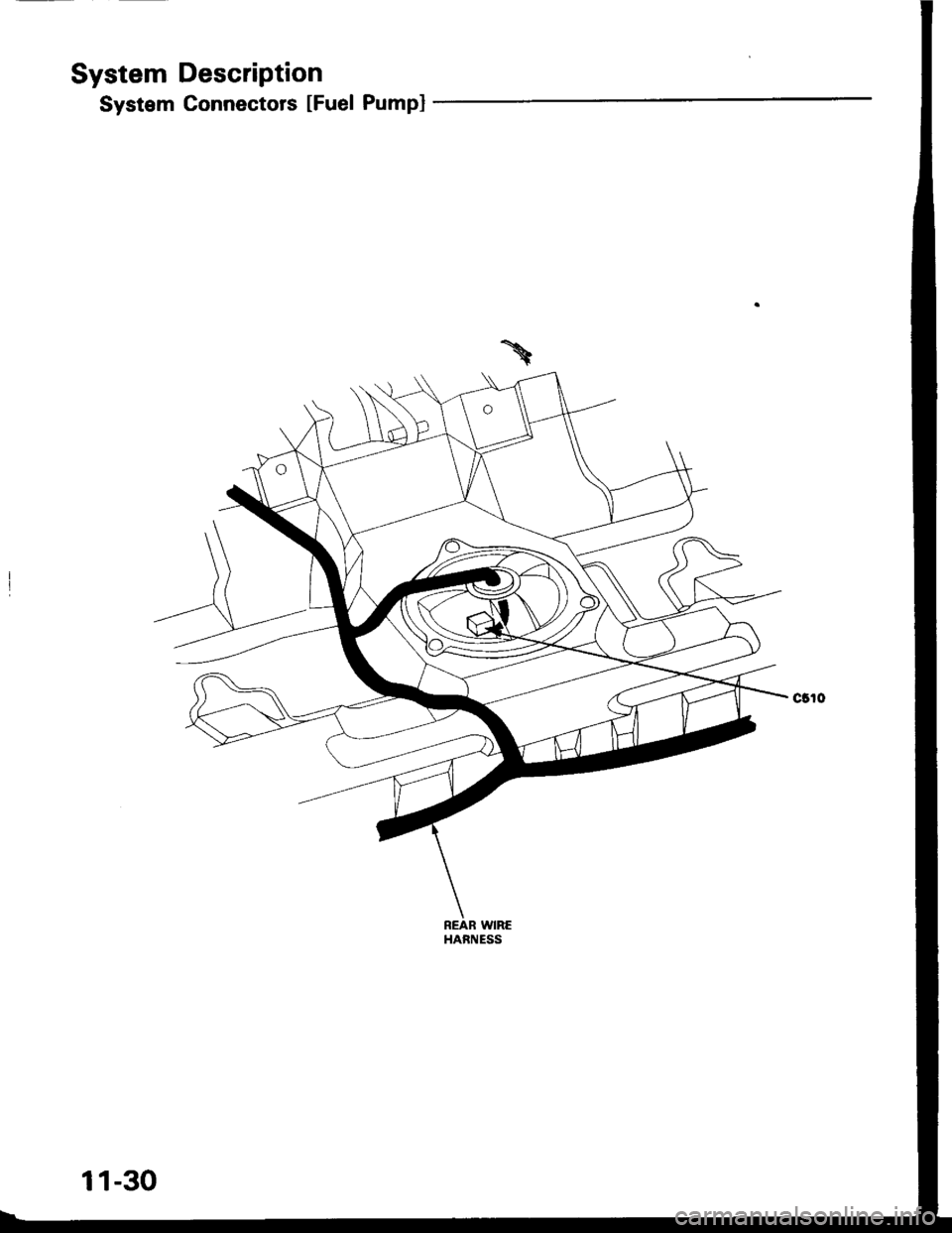
System Description
System Connectors [Fuel Pumpl
REAR WIREHAFNESS
11-30
Page 223 of 1413
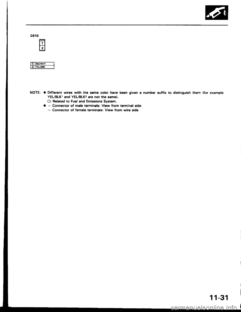
c510
NOTE: a Ditferent wiros with tho samo color hava been given a numb€r sutfix to distinguish them {for example
YEL/BLKI and YEL/BLK, are not th€ same).
O: R€lated to Fuel and Emissions Systom.
a - Connoctor ol malo tarminals: Vi6w from terminal side- Connector ol f6msl€ tarminals: Vi€w from wire sid€
11-31
Page 224 of 1413
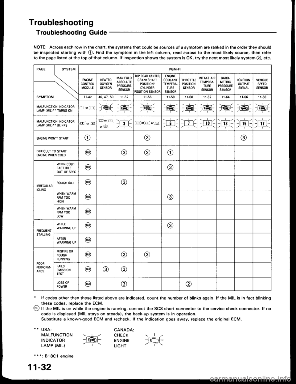
Troubleshooting
Troubleshooting Guide
NOTE: Across each row in the chart. the systems that could be sources of a symptom are ranked in the order they should
be inspected staning with O. Find the symptom in the left column, read across to the most likely source. then refer
to the page listed at the top of that column. lf inspection shows the system is OK, try the next mosr likely system O, etc,
* lf codes other then those listed above are indicated, count the number of blinks again. It the MIL is in fact blinking
^ these codes, replace the ECM.
qy, lf the MIL is on while the engine is running. connect the SCS shon connector to the service check connector. It no
code is displayed {MlL stays on steady), the back-up system is in operation.
Substitute a known-good ECM and recheck. lf the indication goes away, replace the original ECM.
USA:
MALFUNCTION
INDICATOR
LAMP {MIL)
CANADA: ----l CHECK-ltGl- ENGTNE- | - LTGHT
- { -1t-
* * *: 818C1 engine
1-32
SYMPTOM
PGM.FI
ENGINECONTROLMOOULE
HEATEOOXYGENSENSOR
MANIFOLOAESOLUTEPRESSURESENSOR
TOP DEAD CINTTR/CRANKSHAFTPOSTT|ON/CYLINDERPOSITION SENSOR
ENGINECOOLANTTEMPfRA.TURTSENSOR
THROTTTEPOStTtONSENSOR
INfAKE AIRTEMP€RA.TUREsar,rs0R
BARO.METRICPRESSURESENSOR
IGNITIONOUTPUTSIGNAL
vEHtct-ESPfEDSENSOR
11.4246, 47,5011-56l1-581l-6011-6211-641t-661r-68
MALFUNCTION INOICATORLAMP (MIU" TURNS ON1 lor:t:]:lrmr:- i;:i'-tK3t-16l-16l'-\-16l/-----\
-r:+r-
-{"Pr:-o_-16l-.z-\r6t/_-\
MALFUNCTION INOICATORLAMP (MIL)'' BLINKS:O. or-8.-D:o.:@.
o, O'l3l/__-\.E-o.:O: or tr]--i !l/ -i-\| 7 t-/__-\
--l-l-l r0 I/----\| 13 |z_---\
\.--r--l
I r5 t-/.---\-t 17 t-/-]-\
ENGINE WON'T STAffTo@@
DIFFICULT TO STARTENGIN€ WHEN COLO@@(9)o
IRREGULARIDLING
WHEN COTDFAST IDLEouT 0f sPtc@@
ROUGH IDLE@o
RPM TOOHIGH@@
RPM TOOLOW@
FREOUENTSTALLING
WHILE@@
AFTER@
POOnPERFOEM.ANCE
MISFIRE ORROUGHRUNNING@@@
FAITSEMISSIONTEST@@@
Loss 0FPOWER@@@
Page 226 of 1413
Troubleshooting
Self-diagnostic Procedures
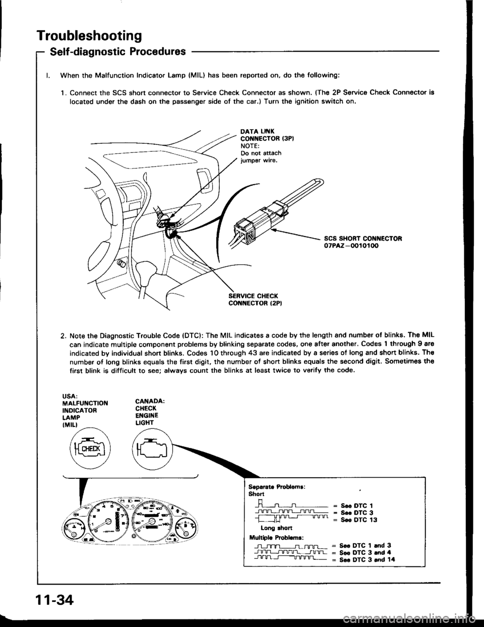
When the Malfunction Indicator Lamp {MlL) has been reported on, do the following:
'1. Connect the SCS short connecto. to Service Check Connector as shown. (The 2P Service Check Connector is
located under the dash on the passenger side of the car.) Turn the ignition switch on.
DATA LII{KCONNECTOR (3PI
NOTE:Do not attachjumper wire.
2. Note the Diagnostic Trouble Code (DTC): The MIL indicates I code by the length 8nd numbsr ot blinks. The MIL
can indicate multiple component problems by blinking separate codes, one after another. Codes 1 through Igre
indicated by individual shon blinks. Codes 1O through 43 are indicated by a series of long and shon blinks. Th€
number of long blinks equals the first digit, the number ot short blinks equals the second digit. Sometimes the
firsr blink is difficult to see; always count the blinks at least twice to verify the code.
MALFUNCTIOI{INDICATORLAMP
CANADA:CHECKENGINELIGHTIMIL}
Sgprrate Prcbaomr:shT
-n-----n- =n- = s.o DTc 1
+!+1].TL;I!!=- = s.. Drc 3-L ,JU '" " " = Sce DTC 13
Long .hon
Multiplr Probl.ln.:
J-l_tx-TL-n-ffu-r- = S€. DTC 1 lnd 3-J.rrU-L-r]tltlr'l- __-tnrua = Sce DTC 3 and 4Jll-lrl-t-----Tt/'tnj]_ = S.. DTC 3 lnd 14
11-34
Page 227 of 1413
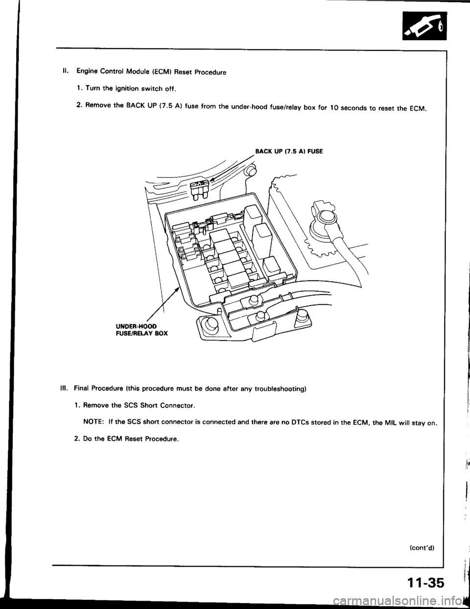
Engine Control Modute {ECM) Reset procedure
1 . Turn the ignition switch otJ.
2' Remove th€ BACK UP (7.5 A) fuse trom the unde.-hood fuse/relay box for lo seconds to reset the EcM.
BACK UP I7.5 AI FUSE
UNDER-HOOOFUSE/RELAY BOX
Final Procedure lthis procedure must be done after any troubleshooting)
1. Remove the SCS Short Connector.
NOTE: lf the SCS short connector is connected and there are no DTCS sto.ed in the ECM, the MIL will stav on.
2. Do the ECM Reset Procedure.
11-35
Page 228 of 1413
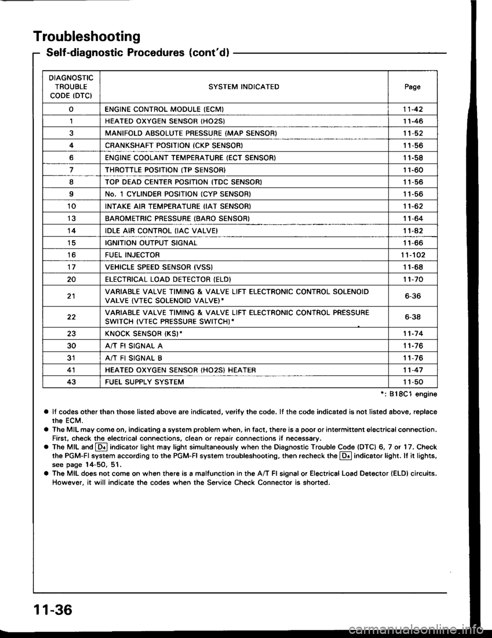
Troubleshooting
Self-diagnostic Procedures (cont'dl
':818C1 engine
a lf codes other than those listed above are indicated, verifv the code. lf the code indicated is not listed above, replace
rhe ECM.
a The MIL may come on, indicating a system problem when, in fact, there is a poor or intermittent electricalconnection.
First, check the electrical connections, clean or repair connections it necessary.
o The MIL and @ indicator light may light simultaneously when the Diagnostic Trouble Code (DTC) 6, 7 or 17. Check
the PGM-Fl system according to the PGM-Fl system troubleshooting, then recheck the l!! indicator light. ll it lights,
see page 14-5O, 51.
a The MIL does not come on when there is a malfunction in the A/T Fl signal or Electrical Load Detector (ELDI circuits.
However, it will indicate the codes when the Service Check Connector is shorted.
DIAGNOSTIC
TROUBLE
CODE (DTCISYSTEM INDICATEDPsge
oENGINE CONTROL MODULE IECM)11-42
,lHEATED OXYGEN SENSOR IHO25)1 1-46
aMANIFOLD ABSOLUTE PRESSURE {MAP SENSOR)11-52
4CRANKSHAFT POSITION (CKP SENSOR)1 1-56
oENGINE COOLANT TEMPERATURE (ECT SENSOR)11-58
THROTTLE POSITION (TP SENSOR}11-60
ITOP DEAD CENTER POSITION (TDC SENSORI1 1-56
9No. 1 CYLINDER POSITION (CYP SENSOR)1 1-56
10INTAKE AIR TEMPERATURE (IAT SENSOR)11-62
13BAROMETRIC PRESSURE (BARO SENSOR}1|-64
14IDLE AIR CONTROL (IAC VALVE}11-42
tcIGNITION OUTPUT SIGNAL11-66
toFUEL INJECTOR1't-102
17VEHICLE SPEED SENSOR {VSSI11-68
20ELECTRICAT LOAD DETECTOR (ELD)'t 1-70
21VARIABLE VALVE TIMING & VALVE LIFT ELECTRONIC CONTROL SOLENOID
VALVE {VTEC SOLENOID VALVE)'6-36
22VARIABLE VALVE TIMING & VALVE LIFT ELECTRONIC CONTROL PRESSURE
SWITCH (VTEC PRESSURE SWITCHI-6-38
23KNOCK SENSOR {KS}-11-7 4
30A/T FI SIGNAL A11-76
3'rA/T FI SIGNAL B1 1-76
4'lHEATED OXYGEN SENSOR (HO25} HEATER11-47
43FUEL SUPPLY SYSTEM1 1-50
11-36