connector HONDA INTEGRA 1994 4.G Repair Manual
[x] Cancel search | Manufacturer: HONDA, Model Year: 1994, Model line: INTEGRA, Model: HONDA INTEGRA 1994 4.GPages: 1413, PDF Size: 37.94 MB
Page 261 of 1413
(From pog6 1 1-7Ol
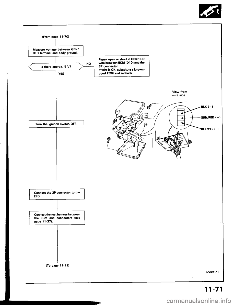
Meaauro voltage betweon GBN/RED ierminal and body ground.
Boplir opon 01lhort in GR /REDwir. batworn ECM (DlOl and tho
3P connoctor.1l wir. i! OK, .ubrtituta. known-good ECM .nd rochock.
13 the.e approx, 5 V?
Turn tho ignition switch OFF.
connect tho loat hamasa botweontho ECM and connectors (soa
pag€ 11-37),
wire side
BLK {_I
GR /NED I-I
BLKIEL { + }
(To page 11-72)
11-71
Page 265 of 1413
PGM-FI System
A/T Fl Signal A/B (A/T only)
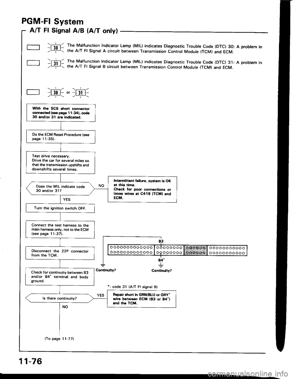
\[l0l- The Maltunction Indicaror Lamp (MlL) indicates Diagnostic Trouble Code (DTC) 30: A problem In-L= the A/T Fl Signat A circuit between Transmission Control Module (TCMI and ECM.
tItil- The Malfuncrion Indicaror Lamp {MlL) indicates Diagnostic Trouble Code {DTCI 31: A problem In-Li!- the A/T Fl Signal B circuit between Transmission Controt Module (TCM) and ECM.
\.__r_/ \.__r_/-l 30 l- o'-l 3t l------ /----\
84'
+ulty? Continuity?
r: code 31 1A/T Fl signal Bl
11-76
Wlth tho SCS ahon connocrolconi|ocd {!o. p.g. 'l 1 -341, codo3O and/or 31 ars indicltod.
Oo ths ECM Resot Proceduro {seepag€ 'l 1-35).
Test drive necessary.Drive the car lor several miles sothat the transmission uDshifts anddownshilts several times.
Intormittant tsilu.o, sy3tem iB OKat thir tima,Chack lor poor connactions otl.ro!€ wiror at C419 (TCM] andECM.
Does the MIL indicare code30 and/or 31?
Turn the ignition switch OFF.
Connect the test harness to th€main harness only, not to the ECM(see p8go l'l-37).
Disconnect the 22P connectorfrom the TCM.
Check lor continuity between B3andlor 84' terminal and bodygrouno.
Ropair lhon in GRN/8LU or GRY'wiro b6twoon ECM (83 or 84'land tho TCM.
(To page 11-77)
Page 266 of 1413
(From page 1 'l-76)
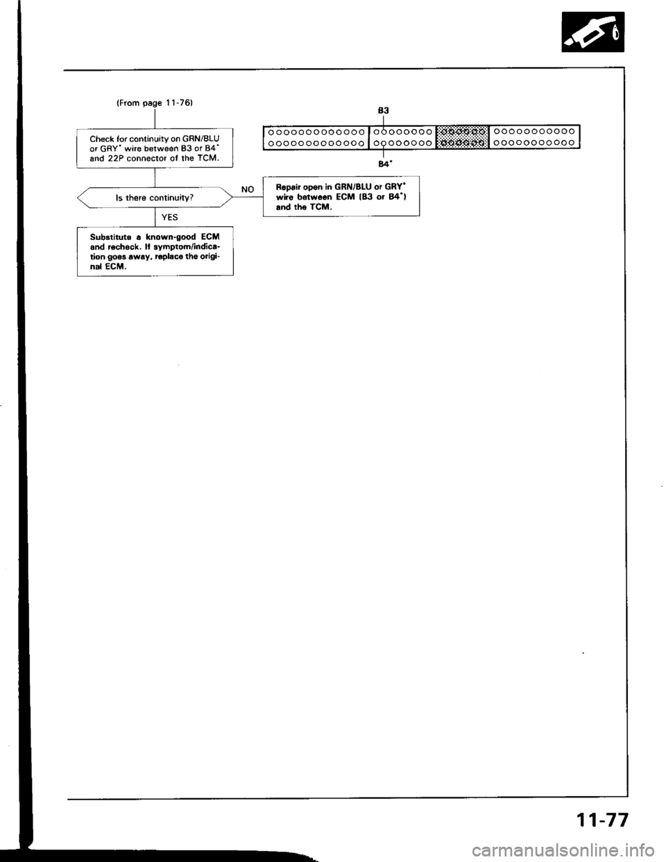
Check for continuity on GRN/BLUor GRY'wire between 83 or 84'and 22P connector of the TCM.
Ropair open in GRN/BLU or GRY'wiro botwoon ECM lB3 or B4'land the TCM,
Substituts a known-good ECMand rochock. ll symptom/indica-tion goos 6way, roplaca tho origi-nal ECM.
11-77
Page 271 of 1413
ldle Control System
ldle Air Control (lACl Valve
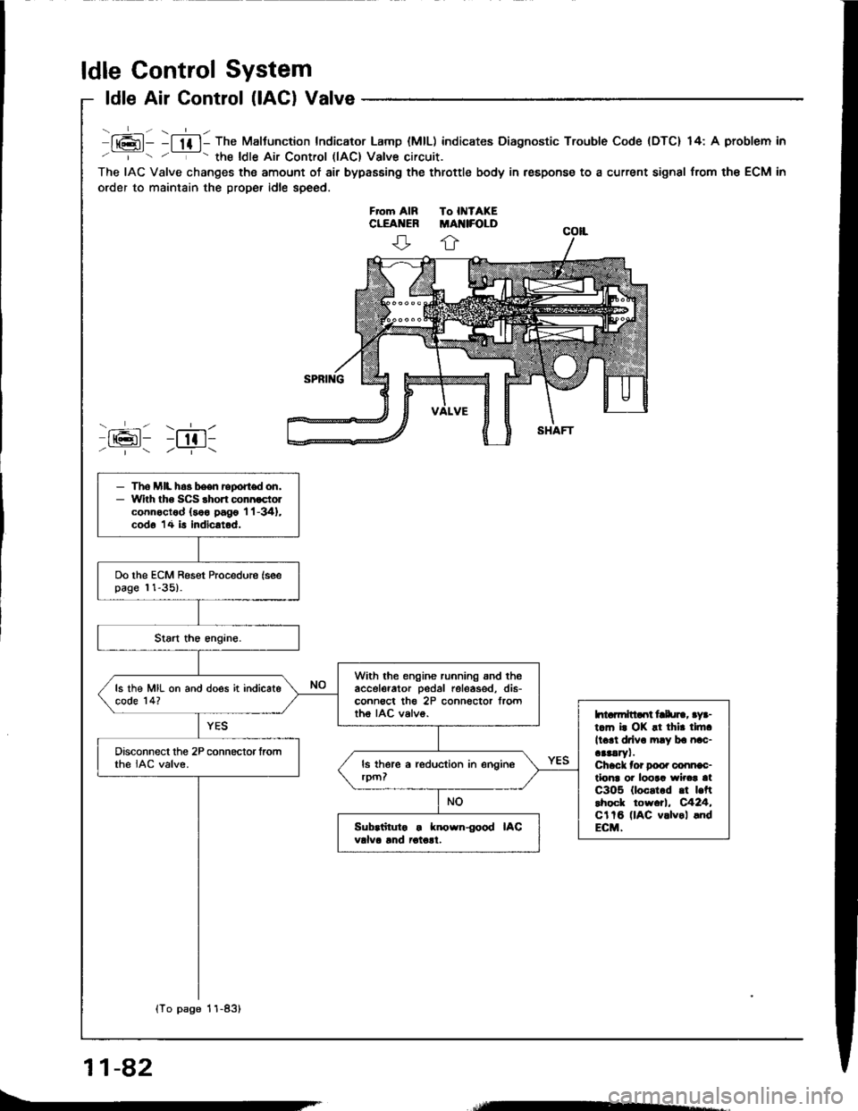
lt6l- -l lf l- The Maltunction Indicator Lamp (MlL) indicates Diagnostic Trouble Code {DTC} 14: A problem in
' '- the ldle Air Control llAC) Valve circuit.
The IAC Valve changes the amount of air bypasEing the throttle body in respons€ to a current signal from the ECM in
order to maintain the proper idle speed.
ffi: r;611/ | /--T-\
- The MIL h.3 been report don,- With tho SCS shon connoctolconnoctod (soo pago 'l 'l -341,
cod6 14 is indicatod.
Do the ECM Reset Procedure (seepage 11-35).
With the engine running snd theaccelerator pedal releas€d, dis-conn€ct th€ 2P connector frorttho IAC valvo.
ls the MIL on and does it indicatecode 14?
htarmitlaot frlu]., aya-t.m i. OK !t thir tlft.
ll.rl drlv. mly ba nac-aaaaryl.Chack tor Doo. conn€c-tlonr oi loora wirca atC3O5 (loc.t.d .t |.ftlhock tow.tl, C424,Cl tB (lAC v.lvol .ndECM.
Disconnect the 2P connector fromthe IAC valve.
Sub.iituto . known{ood IACvdva lnd iotolt.
{To page 11-83}
11-82
Page 272 of 1413
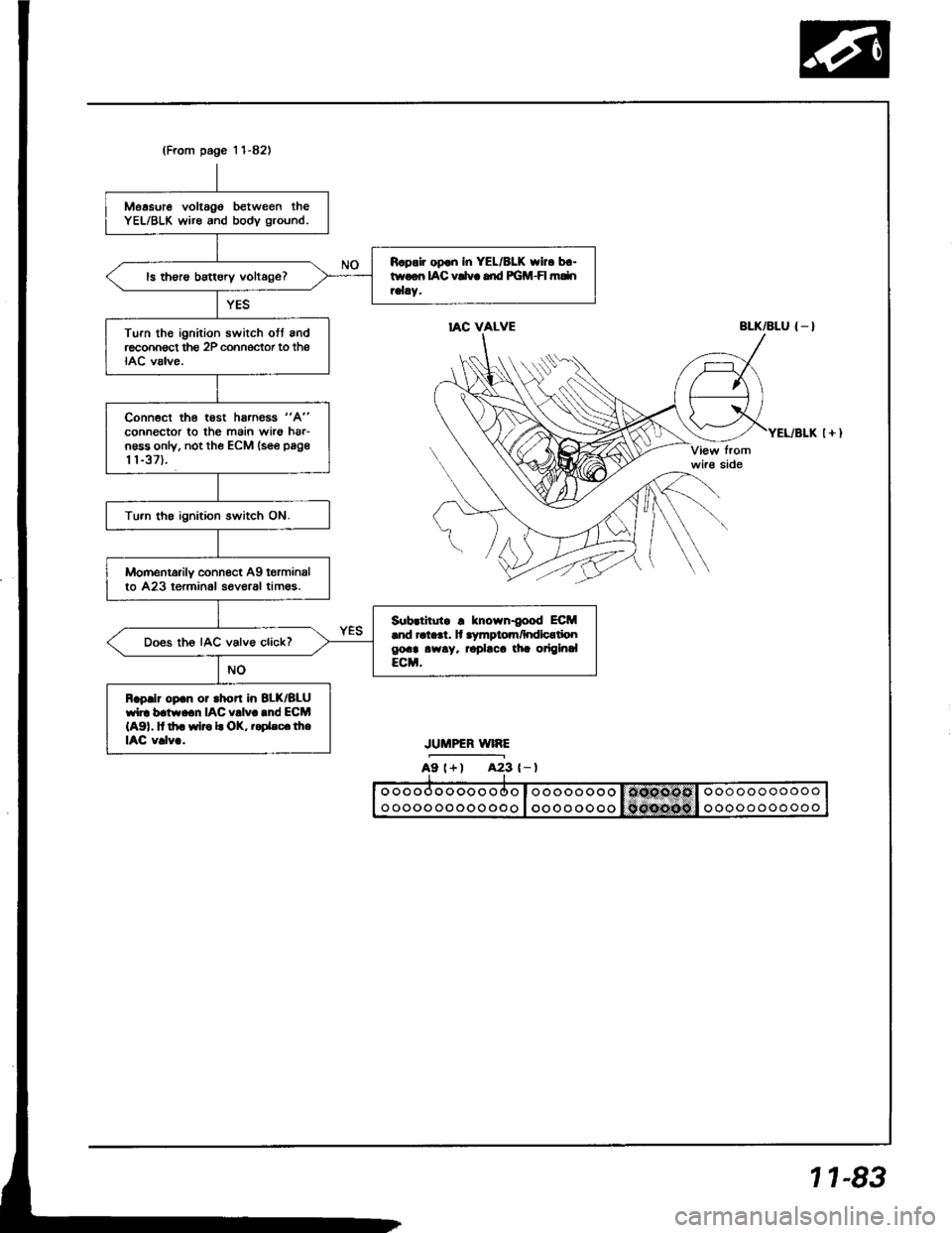
(From page 'l 1-82)
Measure voltago between theYEL/BLK wire and bodv ground.
R.pair op.n In YEL/8LK who b.-twoon IAC vCvc dd PGM-FI mdnrelay.ls th€rs battery voltage?
Turn th€ ignition swirch ott andreconnect thg 2P cohnector to theIAC valve.
Conn€ct the test hs.ness "A"
connector to the main wirs hrr-n6ss only, not the ECM lsee page
t 1-37).
Tu.n tho ignition switch ON.
Momentarily connect Ag torminalto 423 terminol seveaal tim€s.
Sub.titutr ! known{ood ECM.nd ral..t. lt .ymptom/hdlcatioogoa! awsy. rophca tia origlnalECM.
Does th6 IAC valve click?
Raplir op.n or rhort in 8LK/BLUwl]. b.tw.cn IAC v!lv..nd ECM(A91, It th. wlro L OK, r.Dhc.lheIAC v.lv..
IAC VALVEBLK/BLU { _ }
JUMPER WIRE
A9 l+) A23 {-l
1 1-83
Page 273 of 1413
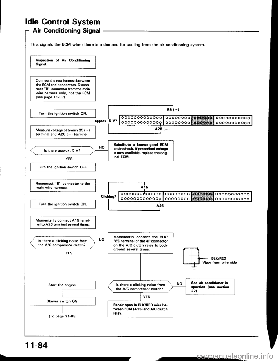
ldle Gontrol System
Air Conditioning Signal
This signals the ECM when there is a demand for cooling from the air conditioning system.
Connect the t€st harness betweenthe ECM and connectors. Discon-nect "B" connector from the mainwire harness onlv, not the ECM{see page 11-37}.
Turn the ignition switch ON.
Measure voltage between 851+ )lerminal and A26 l- I terrninal.
Sub.litut ! known{ood €CMrnd r6
Turn th€ ignition switch OFF.
Reconnect "8" connector to themain wire harness.
Turn the ignilion switch ON.
Momentarilv connect A15 termi-nalto A26 terminsl severaltimes.
Momsntarilv connect the 8LK/RED t€rminal of the 4P connectoron the A/C clutch rel6v to bodyground sevsral times.
ls there a clicking noise fromthe A/C comDressor clutch?
3o6 rlr condhlohar in-rDactlon llaa lac{ion221.
ls there a clicking nois€ lromth€ A/C comoressor clutch?
Rop.ir opon in BLK/BED wiro be-two.n ECM {A15} and A/C clurchrally.
ooooooooooooo
oooooooooooo
oooooooo
oooooooo
ooooooooooo
ooooooooooo
.pprox. 5 V?
426 (- )
Cllcklng?
lTo page
11-84
-
Page 275 of 1413
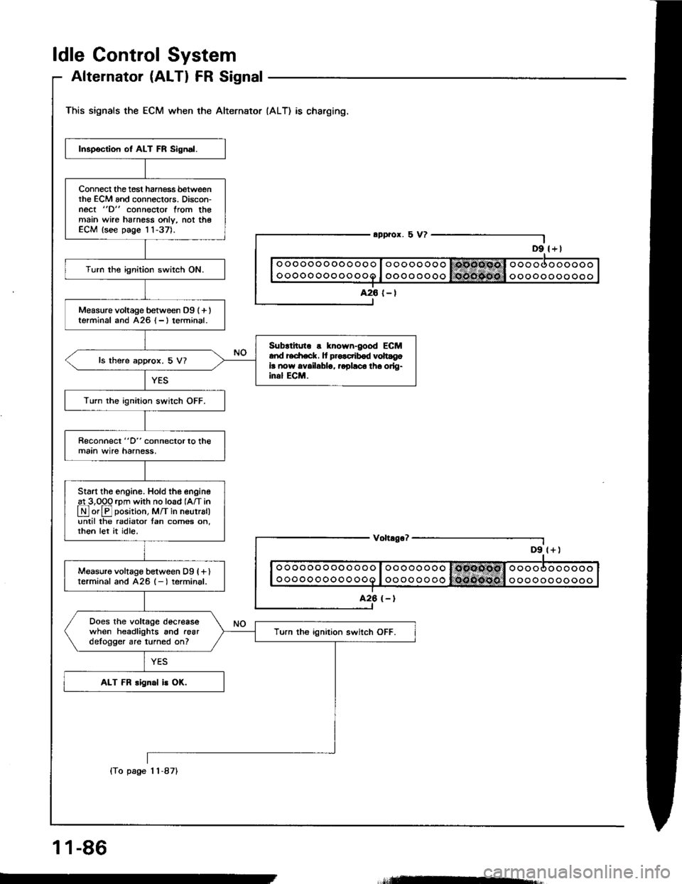
ldle Control System
Alternator (ALTI FR Signal
This signals the ECM when the Alternator (ALT) as charging.
D9 l+)
Inspection ot ALT FR Sign.l.
Connect the tost harness betweenthe ECM and connectors. Discon-nect "D" connector from themain wire harnoss only, not theECM lsee page 11-37).
Turn the ignition switch ON.
Measure voltage between D9 (+ )terminal and A26 {-}terminal.
Sub{inno s known-good ECMand redrack. It pro.ctibod volt gola now availablg, ropllco tha orlg-inal ECM.
ls there approx. 5 V?
Turn the ignition switch OFF.
Reconnect "D" connector to themain wire harness,
Start tho engino. Hold the engine
!L3,099 rpm with no load (A/T in
LN] or El position, M/T in neutral)until the radiator tan comes on,rhen let it idle.
Measuro voltage between Dg (fl
terminal and 426 (- I terminal.
Does the voltage decreasewhen headlights and .eardelogger are turned on?Turn ths ignition switch OFF.
ALT FR rignal is OK.
o oo oo o ooooo
ooooooooooo
Voh.go?
ooooooooooo
ooooooooooo
1 1-86
(To page 1 1-87)
=-
Page 276 of 1413
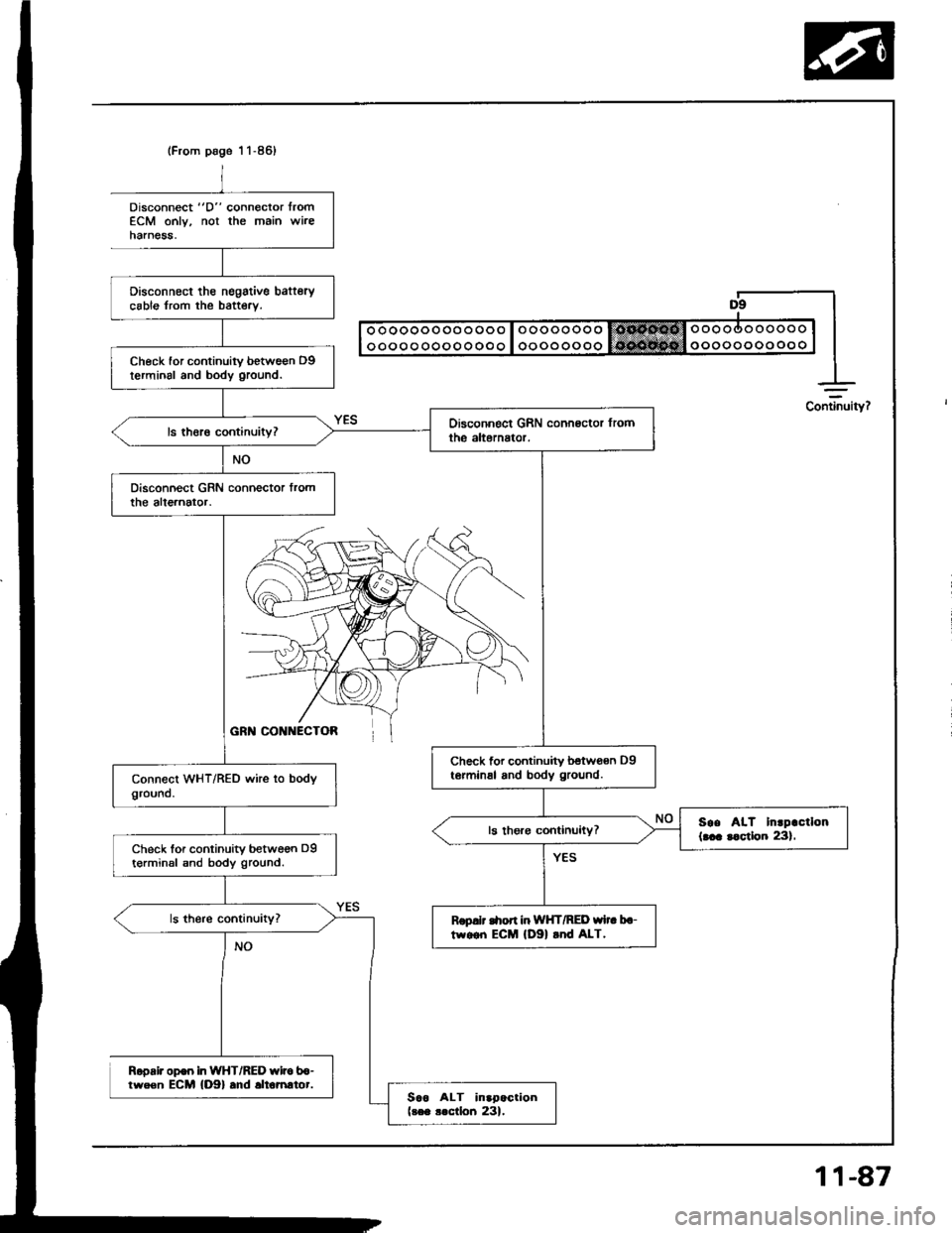
(From page 1 1-86)
Disconnect tho nsgstive bafterycable from the baftery.
Check for continuity betwe€n D9terminal and body ground.
Check for continuity betwoan D9te.minal and body ground.
soe AIT Inrpactlon(... r.ctlon 231.Check lor continuity between D9t€rminsl snd body ground.
Rop.lt C|on in WHT/RED wi.. b.-tw.on ECM lDgl rnd ALT.
Sao ALT inapactionlres .lctlon 231.
Disconnect "D" connector lromECM only, not the main wireharnesa,
Ropair op€o in WHT/RED wito b6-tween ECM {D9} .nd .ltomrtor.
Continuity?
11-87
Page 277 of 1413
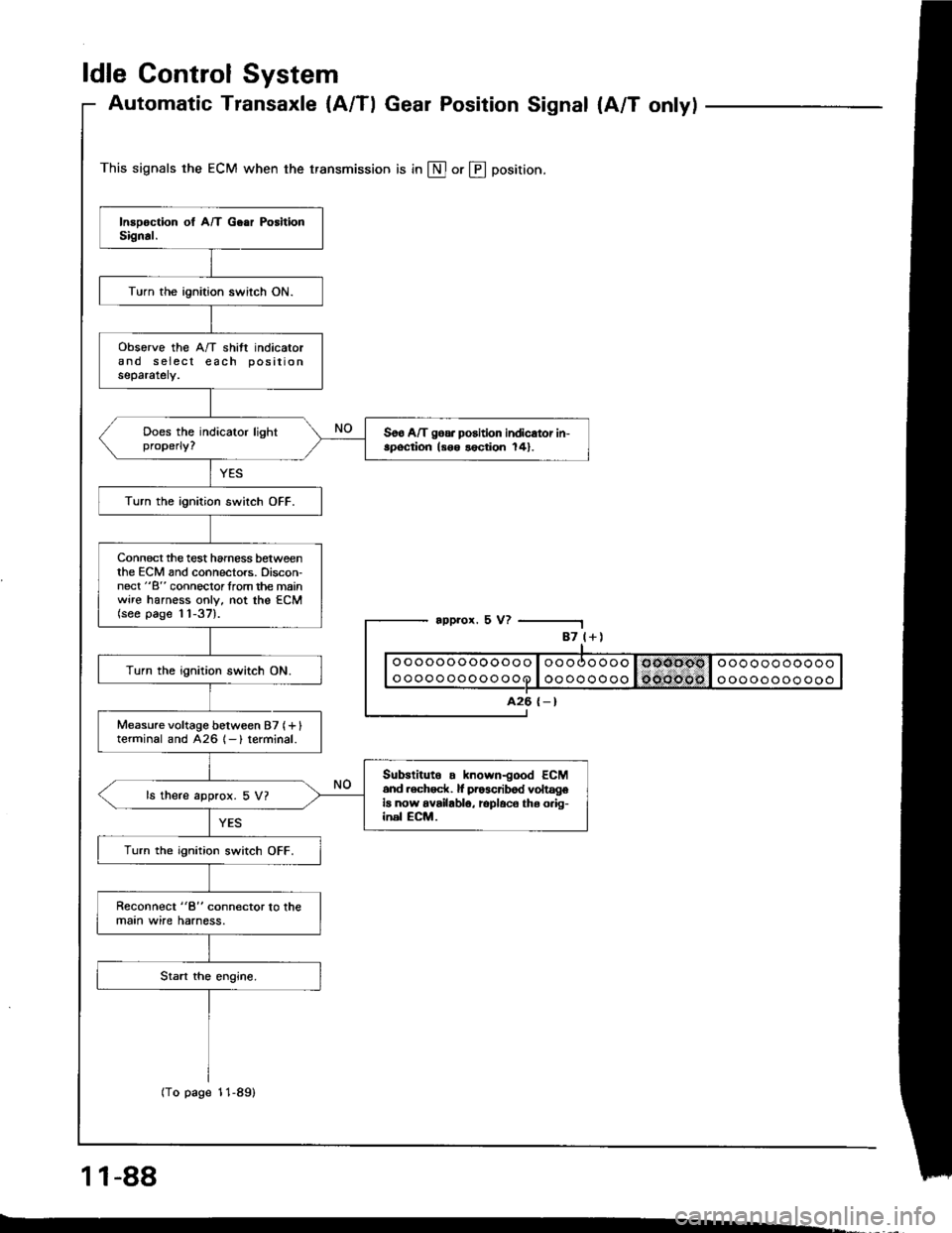
ldle Control System
Automatic Transaxle {A/Tl Gear Position Signal {A/T onlyl
This signals the ECM when the transmission is in @ or @ position.
appror. 5 V?
1 1-88
-.
87 l+)
ooooooooooooo
oooooooooooo
A26 {-}
Turn the ignition switch ON.
obsorve the A/T shift indicatorand s eiecl each positionseparately.
Soo A/T goa. position indicator in-spoqtion ls6o lection 141.
Turn the ignition switch OFF.
Connect the test hamess betweenthe ECM and connectors. Discon-nect "B" connoclorlrom the mainwire harness only, not the ECM(see page 11-37).
Turn the ignition switch ON.
Measure voltage between 87 (+ Iterminal and 426 1- ) terminal.
Subslituto . known-good ECM6nd .ech6ck. lf pr63cribod voltageia now availablo, rcplaco ths o.ig-inel ECM.
ls there approx. 5 V?
Turn the ignition switch OFF.
Reconnect "8" connector lo lhemaan wire harness.
(To page 11-89)
Page 281 of 1413
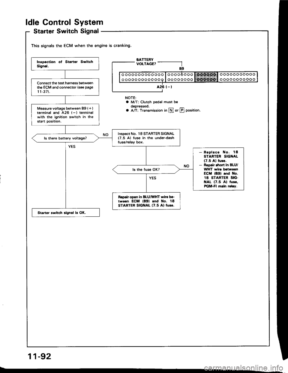
ldle Gontrol System
Startel Switch Signal
This signals the ECM when the engine is cranking.
BATTERYVOLTAGE?
NOTE:a M/T: Clutch pedal must beoeprgsseo.a A/T: Trsnsmission in lll or LIJ position.
11-92
ooooooooooooo
oooooooooooo
A26 {-}Connect the lest harness botweenthe ECM and connector (see page
11,37).
Measure voltage between 89 (+)
terminal and 426 (-) terminalwith the ignition switch in thestart position.
Inspect No. 18 STARTER SIGNAL{7.5 A) fuse in the under-dashfuse/relav box.ls there batterv voltage?
- Roplac. No. 18STARTER SIG AL(7.5 A) lurc,- Rrpsir lhort In BLU/WHT wir. batwccnECM (89) .nd No.18 STARTER SIG.t{AL {7.5 Al 1u..,PiGM-Fl fi.ln rol.y.
R.palr opon in BLU/WHT wir6 b6-tw€.n ECM lB9l and t{o, 18STARTER SIGNAL 17.5 Al lu.o.
Startor .witch .ign.l is OK.