Page 98 HONDA INTEGRA 1994 4.G Workshop Manual
[x] Cancel search | Manufacturer: HONDA, Model Year: 1994, Model line: INTEGRA, Model: HONDA INTEGRA 1994 4.GPages: 1413, PDF Size: 37.94 MB
Page 1312 of 1413
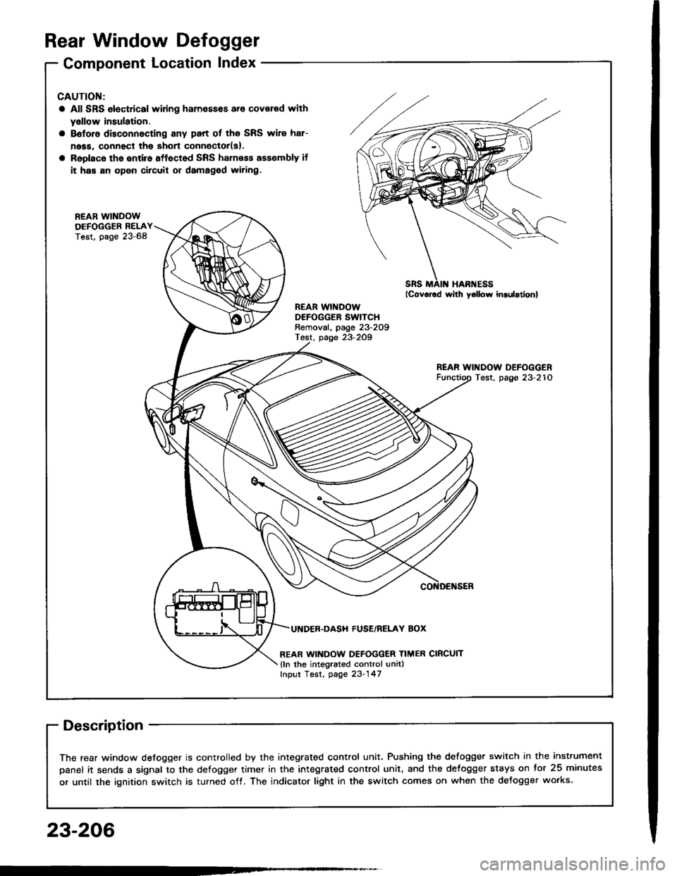
Rear Window Defogger
Component Location Index
CAUTION:
a All SRS olectrical wi ng ham€$6s are covoled with
y€llow insulation.
B6foro disconnocting any part of ths SRS wire har-
ness. connoct tho short connector(s).
Roplacs the ontire affectod SRS harness assombly if
it has an open circuit or damagcd wiring.
REAB WINDOWDEFOGGER RELAYTest, page 23-68
REAR WINDOWDEFOGGER SWITCHRemoval, page 23-209Test, page 23-2Og
REAR WINDOW DEFOGGERTest, page 23-210
UI{DER.DASH FUSE/RELAY BOX
REAR WINDOW DEFOGGER TIMER CIRCUIT
{ln the integrated control unil)fnput Test, page 23-147
SRS MAII{ HAR'{ESS
The rear window defogger is controlled by the integrated control unit, Pushing the defogger switch in the instrument
panel it sends a signal to the defogger time. in the integrated control unit, and the detogger stays on tor 25 minutes
or until the ignition switch is turned off. The indicator light in the switch comes on when the deJogger works.
23-206
Page 1317 of 1413
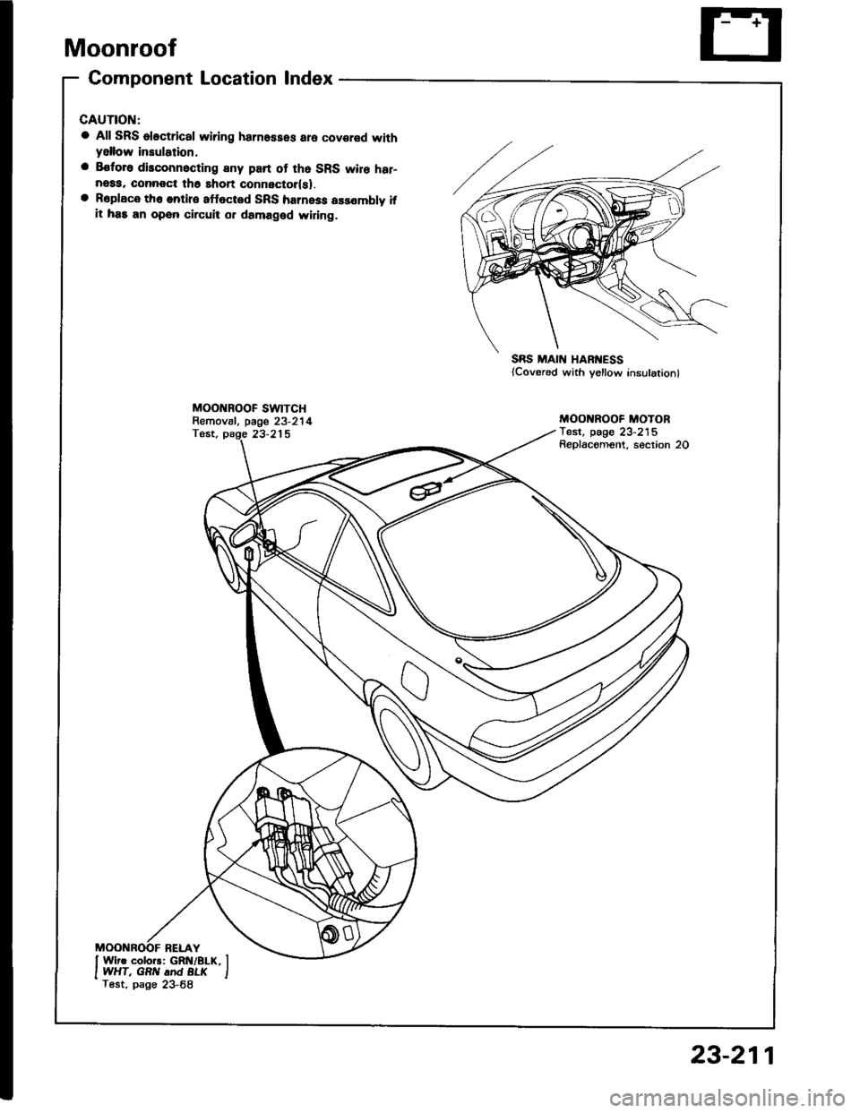
Moonroof
Gomponent Location lndex
a All SRS oloctrical wiring harnesses aro covared withyellow insulation,
a Eoforo disconnocting any part of tho SRS wire har-neaa, connoct th6 shon connector(sl.a Roplace th6 entire 8ff6cted SRS harness assombly ifit has an open circuit or damaged widng.
MOO BOOF SWTTCHRemov8l, page 23-214Test, page 23-215
SRS MAIN HARI{ESS{Covered with yellow insulation)
MOO ROOF MOTORTest, pag€ 23-215Replacoment, section 20
23-211
Page 1322 of 1413
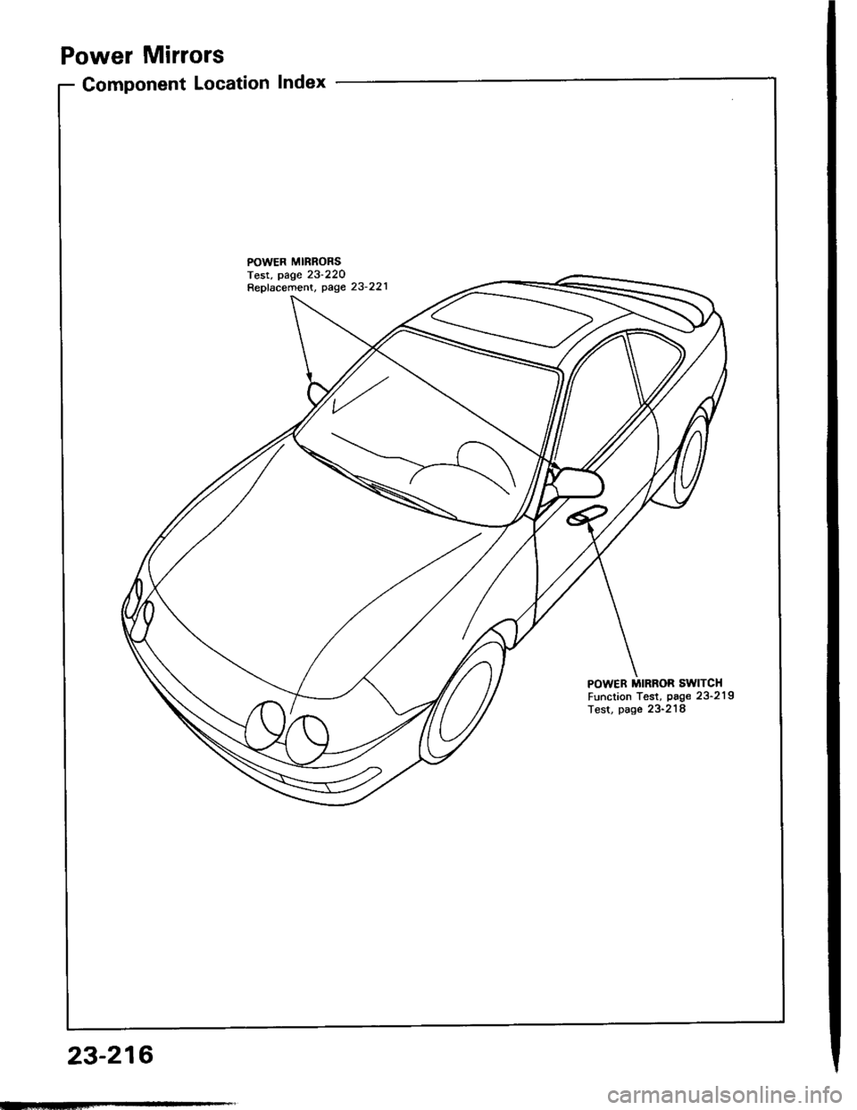
Power Mirrors
Component Location Index
POWER MIRRONSTest, page 23'220Repfacement, page 23'221
POWER MIRROR SWITCHFunction Test, page 23'219Test, page 23-218
23-216
Page 1328 of 1413
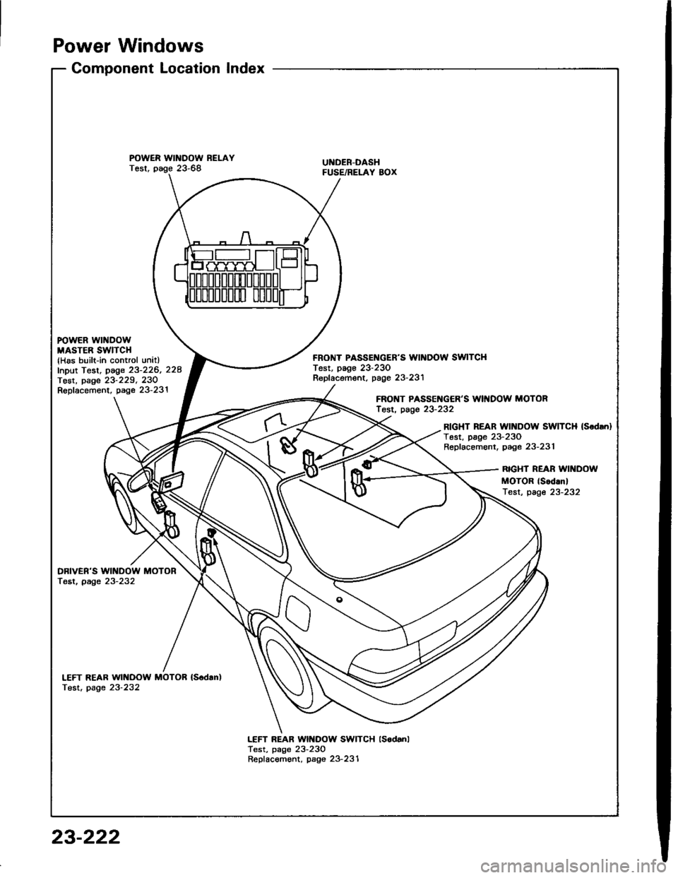
Power Windows
Component LocationIndex
POWER WINDOW RELAYTest, page 23-68UI{DER-DASHFUSE/RELAY BOX
FOWER WINDOWMASTER SWITCH{Has built-in control unitlfnput Test, page 23-226, 228Tost, page 23-229, 23ORopfacement, page 23-231
FRONT PASSEI{GER'S WII{DOW SWITCHTest, page 23-230Repf acement. page 23- 231
FRONT PASSENGER'S WII{DOW MOTORfosr, page 23-232
RIGHT REAR Wll{DOW SWITCH (Sodrn}
Tost, page 23-230Replacement, page 23-231
RIGHT REAR WII{DOW
MOTOR (Sod.nl
Test, page 23-232
DBIVER'S WINDOW MOTORTest, page 23-232
LEFT REAR WINDOW MOTOB {S6dan)Test. page 23-232
LEFT REAR Wlt{DOW SWITCH lsodanlTest, page 23-230Repfacement, page 23-231
23-222
Page 1335 of 1413
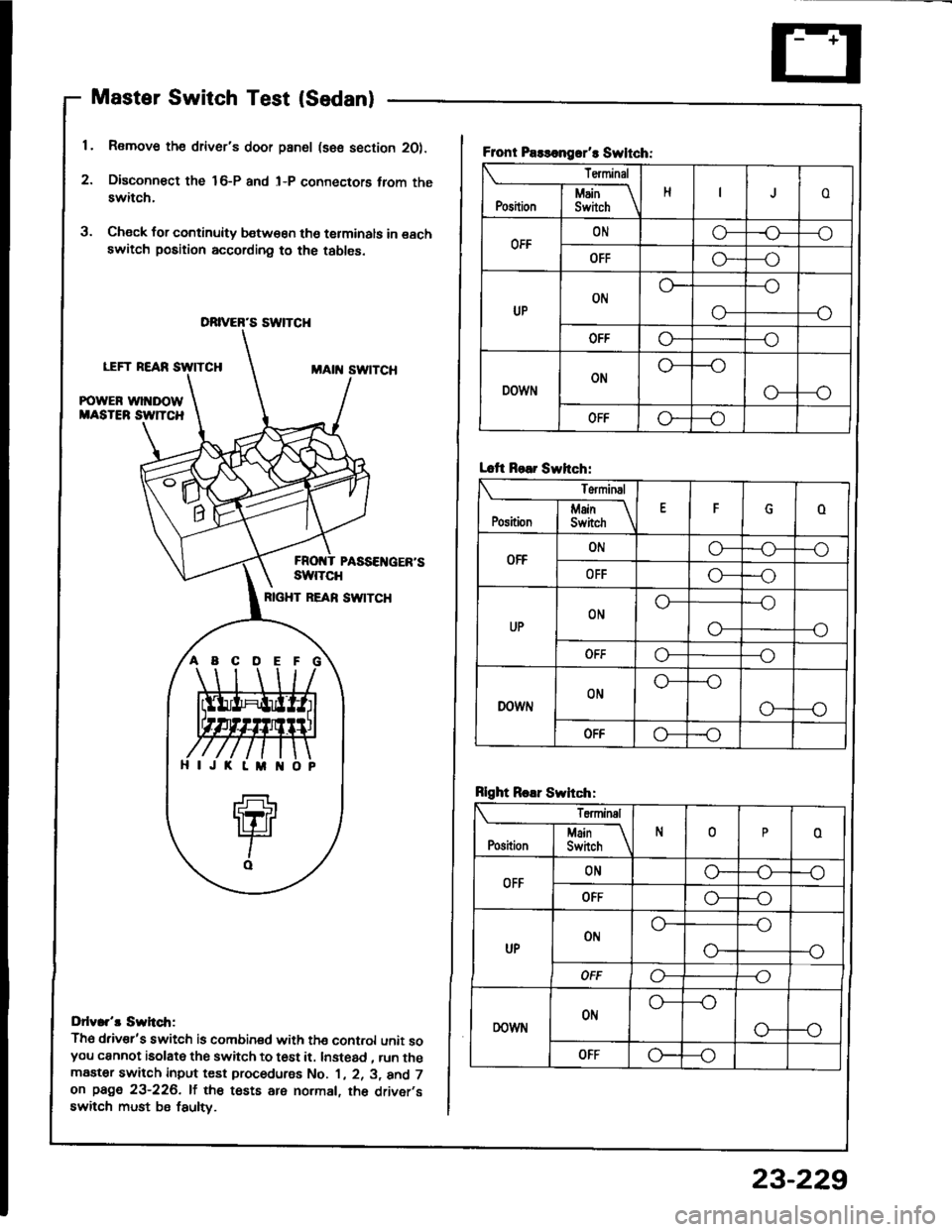
Master Switch Test (Sedan)
1. Remove the driver's door pan6l (sse section 2O).
2. Disconn€ct the 16-P and l-P connectors trom theswitch.
3. Check for continuity b€tw€€n tho terminals in eachswitch position according to the tables.
LEFT REARMAtit swtTcH
POWER wl DOWMASTEB SW]TCH
PASSEI{GER'SswtTcH
RIGHT REAN SW|TCH
Ddv.r't Swh.tr;
Th6 driv€r's switch is combined with the cont.ol unit soyou cannot isolate the switch to t6st it. Instead , run themaater switch input test procedurss No. 1 , 2. 3, and 7on page 23-226. lf the tests are normal, th6 driver,sswitch must be fsulty.
DRIVER'S SWTCH
ABCDE
Front Paslongrr't Swltch:
Terminal
HoI Main \Position I Swirch \
OFFONo-r)--o
OFFG----o
UPON
--o
O-
OFFo---o
DOWNON
o---o
OFFo--_o
Lcft Rear Swhch:
Terminal
EFoj Main IPosition I Switch \
OFFONo-o--o
OFFo---o
UPONo---o
--oo-
ut'fo---o
DOWNONo---o
G---o
OFF-o
Rlght Roar Swhch:
Teminal
N0oI Main If
Position I Switch \
OFFONG_o--o
OFFo---o
UPot'lo---o
--o
OFFo----o
DOWNONo---o
o--o
OFFG---o
23-229
Page 1336 of 1413
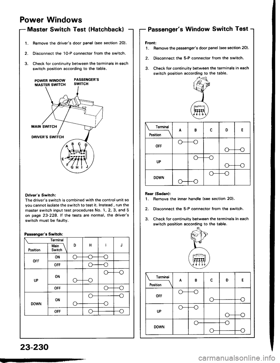
1.Remove the drivef's door panel (see section 201.
Oisconnect the 1O-P connector from the switch.
Check tor continuity between the terminals in each
switch position according to the table.
pOWERWTNDOW PASSENGEB'S
MASTER SWTTCH SWITCH
Drive.'s Switch:
The driver's switch is combined with the control unit so
you cannot isolate the switch to test it. Instead , run the
master switch input test procedures No. 1, 2, 3, and 5
on page 23-228, lf the tests are normal, the d.ivet's
switch must be faultv.
i1\i
\4r-I^l,r
)rvti\
.Fi'ilj
Passengsl'r Switch:
Te.minsl
DHJI Msin \Position I Switch \
OFFONo-(J--o
OFFo--o
UPONo---o
o--
OFFo--o
DOWNONo-
o--o
--o
OFFo--o
Power Windows
Master Switch Test (HatchbacklPassenger's Window Switch Test
23-230
Front:
1 . Remove the passenger's door panel {see section 20).
2. Disconnect the 5-P connector from the switch.
3. Check for continuity between the terminals in each
switch position sccording to the table.
Rear (Sedanl:
1. Remove the inn€r handle (see section 2O)'
2, Disconnect the 5-P connector from the switch.
3. Check for continuity between the terminals in each
switch position according to the table.
Torminal
il;_\
ARD
OFFo-
--o
UPo---o
G_--o
DOWr.lo---o
Terminal
;;__\ID
OFFG_--o
o---o
UPG_--o
o---o
DOWNo---o
o-
Page 1339 of 1413
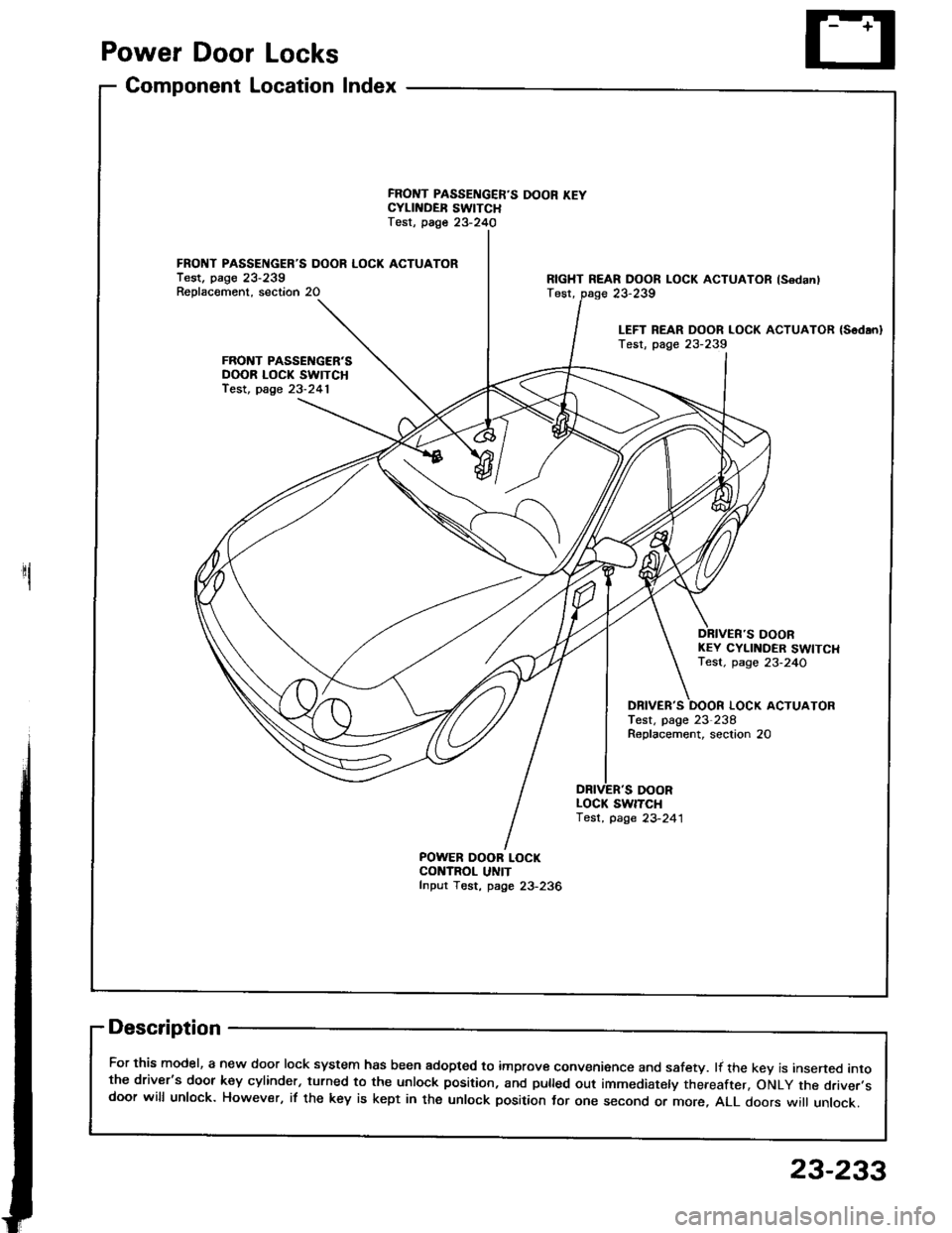
Power Door Locks
Component Location Index
1
FRONT PASSENGER'S DOOR LOCK ACTUATORTest. pago 23-239Reolacement. section 20
FRONT PASSENGER'SDOOR LOCK SWITCHfest, page 23-241
FRONT PASSENGER'S DOOR KEYCYLII{DER SWITCHTest, page 23-240
POWER OOOR LOCKCONTROL UNITfnput Tost, page 23-236
RIGHT REAR DOOR LOCK ACTUATOR lsodanlTest,
DOORKEY CYLINDER SWITCHTest. page 23-24O
DBIVER'S
DOOR
LOCK ACTUATORTest, page 23-238Roplacement, seclion 20
LOCK SWITCH'lest, page 23-241
Description
For this model, a new door lock system has been adopted to improve convenience and safety. lf the kev is insened intothe driver's door key cylinder, turned to the unlock position, and pulled out immediately thereafter, oNLy the driver.sdoor will unlock. However, if the key is kept in the unlock position tor one second or more, ALL doors wi
unlock.
23-239
LEFT REAR DOOR LOCK ACTUATOR {Sodan}Test, page 23-239
23-233
Page 1348 of 1413
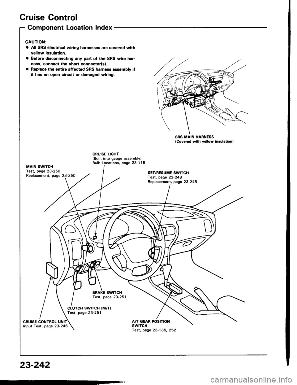
Cruise Control
MAIN SWITCHTest, page 23-250Replacement, page 23-250
Component Location Index
a All SRS 6l6ctrical wiring harnessos aro covorod with
yallow insulation,
a Bofo.6 disconnecting any part of th6 SRS wire har-
ness, connoct th€ shon conneclor(s).
a Replaco the ontiro affected SRS halness assombly if
it has an op€n circuit or damagod widng.
SRS MAIN HARNESS(Cov.rod wilh yollow In.ulation)
CRUISE LIGHT(Built into gauge assembly)Bulb Locations, page 23-115
SET/RESUME SWITCHTest. page 23-248Repfacemont, page 23-248
BRAKE SWITCHTest. page 23-251
CLUTCH SWITCH (M/TI
Test, page 23-251
CRUISE CONTROLfnput Test, page 23-246A/T GEAR POSITIOI{swtTcHTest, page 23-136, 252
23-242
Page 1349 of 1413
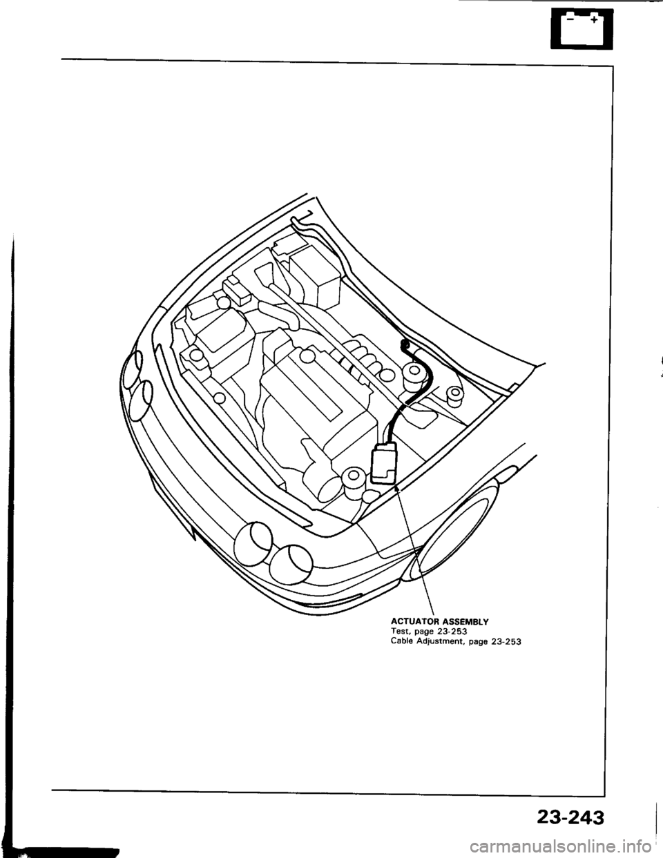
ACTUATOR ASSEMBLYTest, page 23-253Cable Adjustment, page 23-253
23-243
Page 1352 of 1413
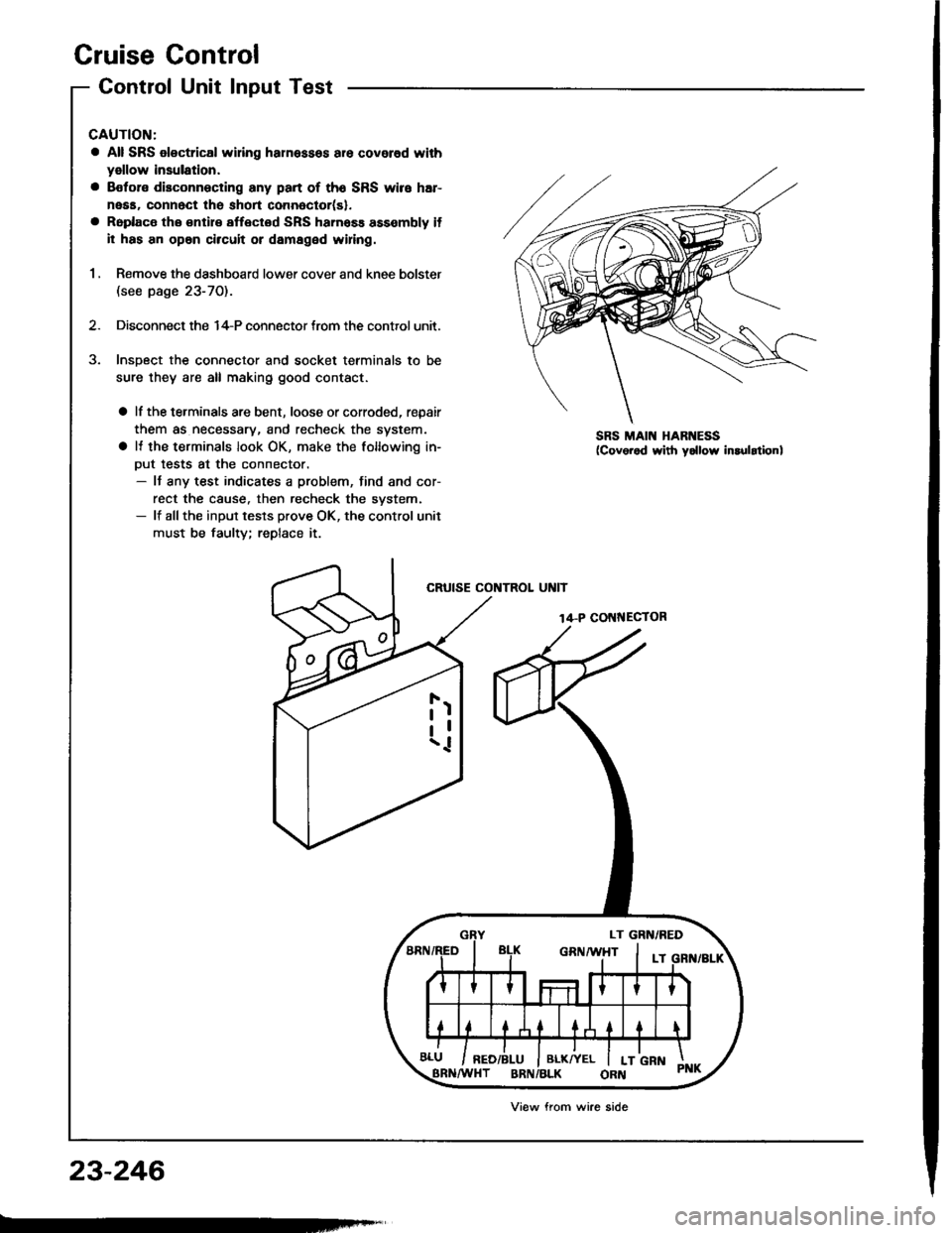
Cruise Control
Control Unit Input Test
CAUTION:
a All SRS olectrical wi ng harnessos are covored with
yellow insulation.
a Botore disconnecting any part of th6 SRS wire har-
neaa, connect the short connoctor(sl.
a Roplace the €ntir€ affectod SRS hamass assembly il
il has an opan circuit or damaged wifng.
1 , Remove the dashboard lower cover and knee bolster(see page 23-70).
2. Disconnect the 14-P connector trom the control unit.
Insoect the connector and socket terminals to be
sure they are all making good contact.
a lf the terminals are bent, loose or corroded, repair
them as necessary, and recheck the system.
a It the terminals look OK, make the following in-
Dut tests at the connector.- It any test indicates a problem, find and cor-
rect the cause. then recheck the svstem.- lf allthe input tesls prove OK, the control unit
must be faulty; replace it.
CRUISE CONTROL UNIT
14-P COI{NECTOR
SRS MAIN HARNESS
23-246
Viow from wire side