Page 98 HONDA INTEGRA 1994 4.G Workshop Manual
[x] Cancel search | Manufacturer: HONDA, Model Year: 1994, Model line: INTEGRA, Model: HONDA INTEGRA 1994 4.GPages: 1413, PDF Size: 37.94 MB
Page 1206 of 1413
Charging System
Troubleshooting
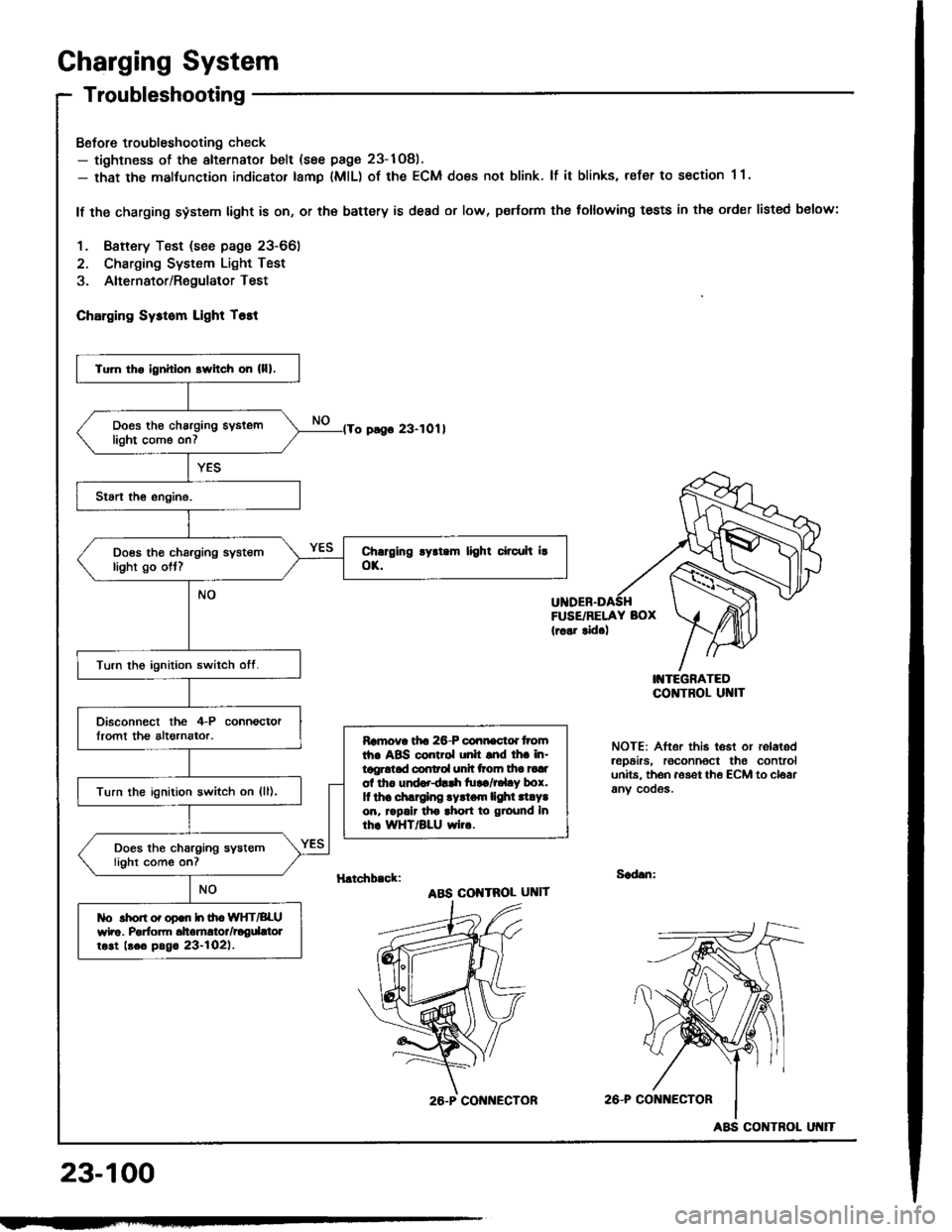
Bofore troubleshooting check- tightness of the alternator belt (see page 23-1Og).- that the malfunction indicator tamp lMlL) of the ECM does not blink. lf it blinks, refer to section 1 1.
lf the charging system light is on, or th€ battery is dead or low, p€rtorm the following tests in the order listed below:
1. Baftery Test (see page 23-66)
2. Charging System Light Test
3. Alternator/RegulatorTest
ChErging Sysrom Light T6tt
o pago 23-1011
FUSE/RELAY BOX(r..r tid.)
I'{TEGRATEDCO]TTROL UI{IT
NOTE: After this test or relaledrep6irs, roconnoct the controlunits. th6n aoset th€ ECM to cloarany cooos.
H.tchb.ck:Sad.n:
ABS COI{TROL UNIT
2A-P CONi{ECTOR
23-100
Tu]n tho ignhlon srvitch on (lll.
Does th€ charging syslemlight come on7
Does tho charging systemlight go ott?
Turn the ignition switch otf.
Disconnect the 4-P connoctorlromt th€ altornator.Ramova tfto 26-P connactd tromth. ABS control unh snd lh. in-tggrotad conrol unh ttoln tha tadol tho und..dlrh tu!a/r.l.y box.It thr .hlrglng .yrtom lighl .l.Y.on, rrpalr tho ahon to ground Inrhr WHT/BLU wi...
Turn the ignition switch on {ll),
Does the charging systemlight come on?
tlo rhon o. opon h ih. WIfT/BLUwho. Porfom dtomrtor/rogdttolrost beo pag. 23-l02l.
26.P CON ECTOR
ABS CONTROL
Page 1207 of 1413
lFrom page 23-10O)'No. 24 (15 A): 818B'lNo. 24 (20 A): 818C1ongrneengine
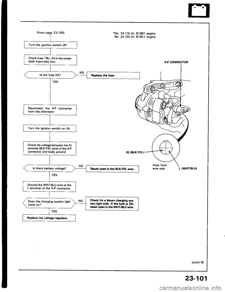
Turn the ignition switch ott.
Check fuse *No. 24 in the under-dash tuse/relay bor.
Disconnect the 4-P connectorIrom the alternator.
Turn the ignition switch on {ll).
Ch6ck forvoltago between tho lGterminal (BLK/YEL wire) of rho il-Pconnector and body ground.
ls there battery voltage?Rgp.i. op.n in th. BLK|'EL wiro.
Ground the WHT/BLU wire at theL terminal ot the 4-P connector.
Chock for ! blown chrrging ry3-rom llghr bulb. It rh. butb i! oK,ropair open in lho IiYHT/BLU wiro.
Does the charging system lightcome on?
wirg sideL IWHT/BLUI
(cont'd)
23-101
Page 1208 of 1413
Charging System
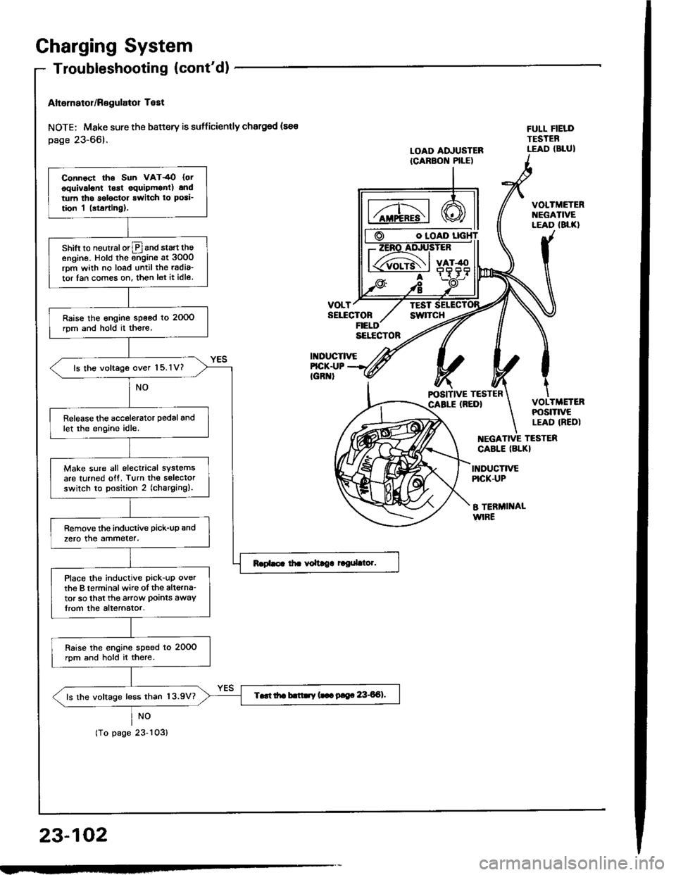
Altornator/Regulator Test
NOTE; Mske sure the battery is sufficiently chargod (sa€
page 23-66).
NO
tropagezJ-ruJ,
O IOAD
VOLTTESTSELECTONswlTcH
II{DUCTIVE
FULL FIELDTESTEBLEAD (BLUILOAD ADJUSTERICARBON PILE)
FICK.I.|PIGR '
VOLTMETERt{EGATIVELEAD (8LK}
VOLTMETERPOStTtVELEAD IREDI
EGATIVE TESTER
CABLE (BLKI
INDUCTIVEPICK.UP
B TERMI]TALWIRE
23-102
Connoct tho Sun VAT4O {otooulvslont lgrt equipmonl) andtum tho s6l6ctor rwitch ro posi_
tion I |rtarting).
shift to neurralorlPland start theengino. Hold the ;;gine at 3oO0rpm wiih no load until the radia_
tor lan com€s on. then let it idle.
Raise the engine speed to 2OOOrom and hold il there.
ls lhe voltage over 15.1V?
Release the accelerator pedal andlet the engino idle.
Make sure all electrical systemsare turned otf. Turn the selectorswilch to position 2 (charging).
Remove the inductive pick-up and
zero the ammeter.
Place the inductive pick-uP overthe B terminalwire oI the altgrna-tor so that the arow Doints awaytrom the alternator.
Raise the engins speed lo 20OOrpm and hold it there.
T..t itr b.ttry (.- 9|e. 8€Al.ls the voltage less than 13.9V?
Page 1209 of 1413
(From page 23-1021
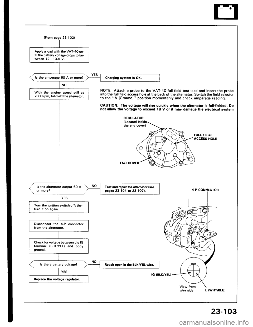
Apply a load wirh the VA'-4O un-til the battery voltage drops to be-tween 12- 13.5 V.
ls the amperage 60 A or more?
With the engine spe6d still at2OOO rpm, full-tield the altemalor.
Toat rnd rooalr d|e dtomEtor {soopsg.. 23-104 to 23-tO7).
Turn the ignition switch off; thenturn at on again.
Disconnocl lhe 4-P connectorIrom the altornator.
Check lor voltage between the lGterminal (BLK/YEL) and bodyground.
ls there battery vokage?Rop.ii open in tho BLK/YEL wiro.
NOTE; Attach a probe to the VAT-4O full field test lead and insert the orobeinto the full tield sccess hole at the back of the alternator. Switch the field selectorto the "A (Ground)" position momentarily and check amperage reading.
CAUTION: The voltago will ris6 quickly whon the slternator is full-fiolded. Donot allow th€ voltago to oxc66d 18 V 01 it may damage the elect.ical system
REGULATOR
{Locatodthe end cover)
FULL FIELDACCESS HOLE
L IWHT/BLUI
4-P CONNECTOR
IG IBLKATELI
wire side
23-103
Page 1210 of 1413
Charging System
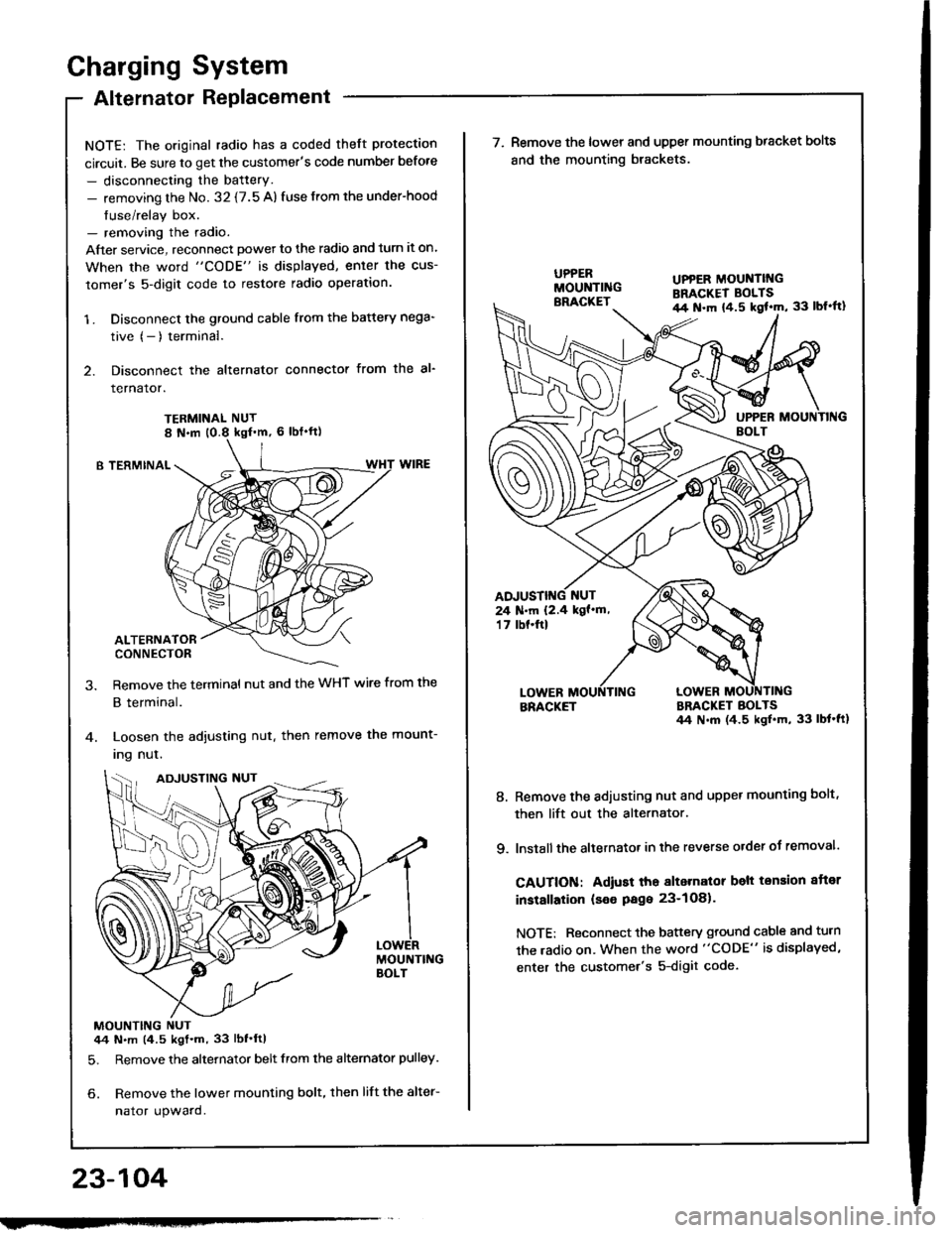
Alternator Replacement
NOTE: The original radio has a coded theft protection
circuit. Be sure to get the customer's code number before
- disconnecting the battery.- removing the No. 32 {7.5 A) fuse from the under-hood
fuse/relay box.- removing the radio.
After service, reconnect powet to the radio and turn it on.
When the word "CODE" is displayed, enler the cus-
tomer's 5-digit code to restore radio operation.
1 . Disconnect the ground cable from the battery nega-
tive (- ) terminal.
2. Disconnect the alternator connector from the al-
rernaror.
TERMINAL NUT
B TERMINAL
ALTERNATORCONNECTOR
Remove the terminal nut and the WHT wire from the
B terminal.
Loosen the adjusting nut. then remove the mount-
Ing nul.
MOUNTING NUT44 N.m (4.5 kgt.m, 33 lbf'ftl
5. Remove the alternator belt from the alternator pulley.
6. Remove the lower mounting bolt, then lift the alter-
nator upward.
23-104
ADJUSTING NUT
w
UPPER MOUNTII{GBRACKET BOLTSil4 N.m {4.5 kgl'm, 33 lbl'ft}
24 N.m 12.4 kgf'm,'t 7 tbf.ftl
\ (^,-(\
\-/ I
7. Remove the lower and upper mounting bracket bolts
and the mounting brackets.
BRACKETBRACKET BOLTS44 N.m (4.5 ksl.m, 33 lbt'ft1
8. Remove the adiusting nut and upper mounting bolt,
then lift out the alternator.
9. lnstall the altetnator in the reverse order of removal.
CAUTION: Adiust tho alternalor belt tension aftor
installation (seo Page 23-1O81.
NOTE: Reconnect the battery ground cable and turn
the radio on. When the word "CODE" is displayed,
enter the customer's 5-digit code.
Page 1211 of 1413
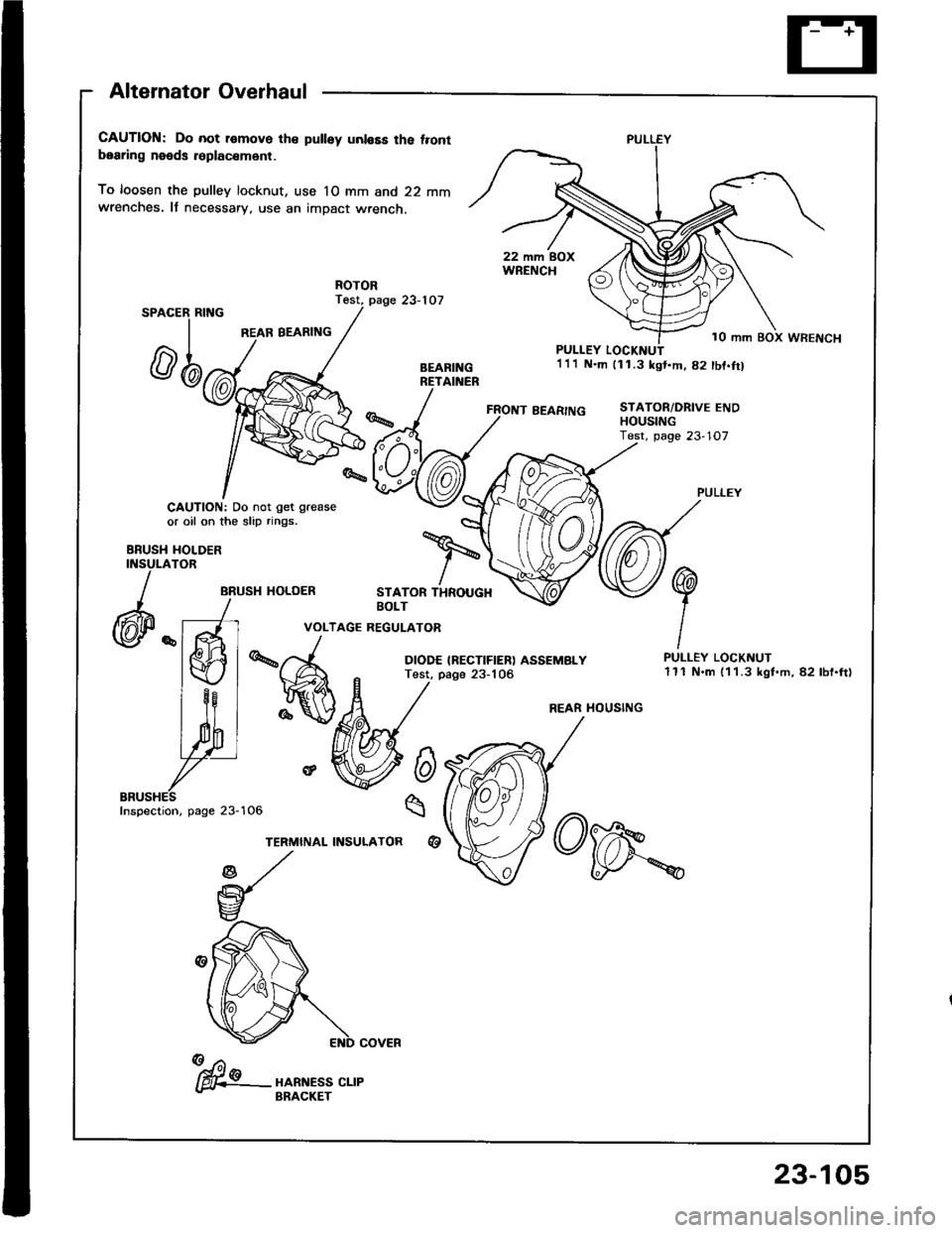
Alternator Overhaul
CAUTION: Do not r€move th€ pulley unl€Es the t.ontbearing needs r6placsm6nt.
To loosen the pulley locknut, use 10 mm and 22 mmwrenches. It necessary, use an impact wrench.
Test, page 23-107SPAC
REAR BEARING
ER RING
rl
@n
CAUTION: Do not get grease
or oil on the slip rings.
HOLDERTOR
ARUSH HOLOER
FRONT BEARING
PULLEY LOCKI{UT1'll N.m 111.3 kgt.m,82 tbf.trl
STATOR/DRIVE ENDHOUStt{G
BBUSHINSULA
)
(@P "
STATOR THROUGHBOLT
VOLTAGE REGULATOR
DIODE IRECTIFIER) ASSEMBLYTest, page 23-106
6
q
%A
re
TERMINAL INSULATORqt
PULLEY LOCKNUT111 N.m (1 1.3 kgt.m, 82 lbf.ft)
PULLEY
10 mm BOX WRENCH
REAR HOUSING
Inspection, page 23-
fu"- "o*n.r" ".,"- BRACKET
23-105
Page 1215 of 1413
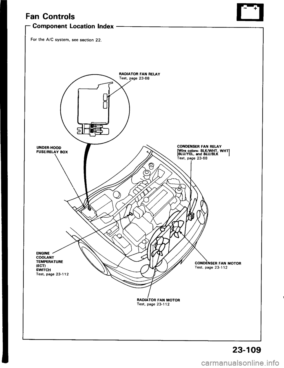
Fan Gontrols
Component Location Index
For the A/C system, see section 22.
UNDER-HOODFUSE/RELAY BOX
RADIAIOR FAN REI.AYTest, page 23-68
CONDCNSER FAI{ BELAYlwir6 color3: ELKnirHT, WHTIIBLUryEL, and BLU/BL( ITest, page 23-68
ENGII{EcooLA TTEMPERATURE{ECT)SwlTCHTesr, page 23-'l 12
FAN MOTORTest, page 23-112
BADIATOR FAN MOTORTest, page 23-1 12
23-109
Page 1219 of 1413
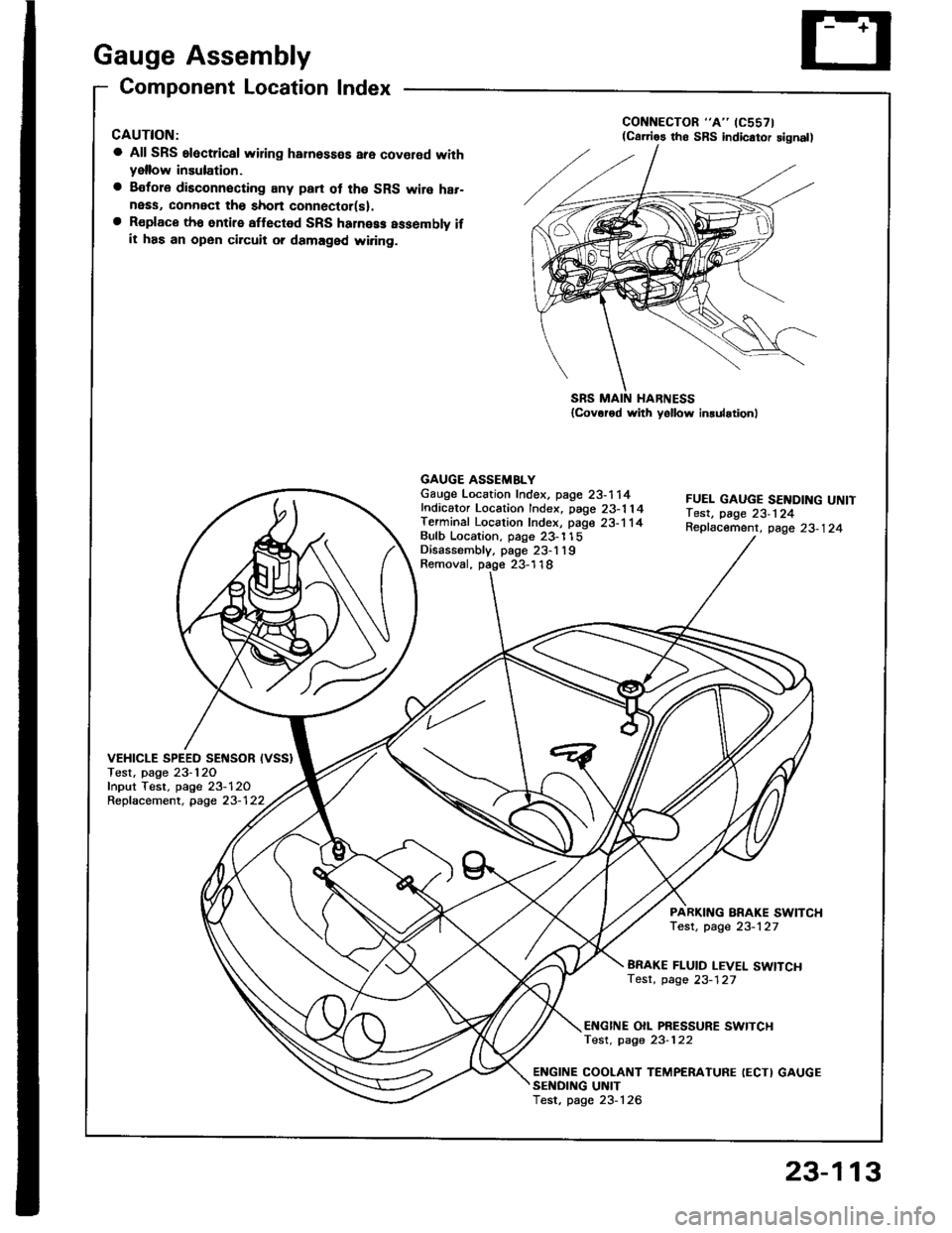
Gauge Assembly
Component Location Index
CAUTION:
a All SRS electrical wiring harnosses are cov€rod withyellow insulation.
a Bofore disconnecting any prn ot th€ SRS wire har-ness, connect tho short connector(sl.a R€place th6 entirs affGcted SRS halne$ assembly ifit has an open circuit o? damaged wiring.
SRS MAIN HARNESS{Cov.r6d with yollow inrularionl
GAUGE ASSEMBLYGauge Location Index, page 23-114Indicator Location Index, page 23-1 14Terminal Location Index, page 23-114Bulb Location. page 23-'l 15Disassembly. page 23-1 19Removal, page 23-118
FUEL GAUGE SENDING UNtTTest, page 23'124Repfacemenr, page 23-124
VEHICLE SPEEO SENSOB IVSS}Test, page 23-120fnput Test. page 23-120Repfacement, page 23-122
PARKITTG BRAKE SWITCHTest, page 23-127
BRAKE FLUID LEVEL SWITCHTesr, page 23-127
EI{GINE OIL PBESSURE SWITCHTest, page 23-122
ENGINE COOLANT TEMPERATURE IECTI GAUGESENOING UNITTest, page 23-126
(C61'ios tho SBS indicator signal)
23-113
Page 1220 of 1413
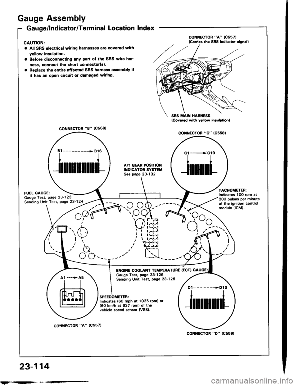
Gauge Assembly
Gauge/lndicator/Terminal Location Index
CAUTIOI{:
a All SRS olectrical wiring harnessos aro covorod with
yellow insulation,
Belol€ disconnecting any part ot tho SRS wiro hat-
nesa. connoct the short connoctol(El.
Replaco th6 entire aff6cted SRS hamess sssombly lf
it has an open circuil or damagod widng.
co r{EcroR "c" (c558}
FUEL GAUGE:Gauge Test, page 23-123
Sending Unit Tost, page 23-124
23,-114
A/T GEAR POSIT|OIIDICATOR SYSTEISee pags 23-132
E GI[{E COOLAI{T TEIIPEFATURE IECTIc6uge TEst, p6g6 23-126Sending Unit Tsst, pago 23-126
TACHOMETER:Indicatos lOO rpm at20O puls€s per minul€of the ignition controlmodul€ llCM).
SPEEDOMETER:Indicates (60 mph 6i 1025 rpml or{60 km/h at 637 rem) of th€v€hicle spe6d sonsor lVSSl.
CoNNECTOR "8" (c5601
Bi ----------+ B16Cl ----+ClO
f',. /i)
)Y
-"b
\_./ \J \-___--
a1 -----> A5
Dl-------.>D13
col{]{ECTOR "D" (C5591
rtrF --
coNNECfOR "A" (C557)
Page 1225 of 1413
![HONDA INTEGRA 1994 4.G Workshop Manual Disassembly
NOTE: Handle the terminals and printed circuit boards caretully to avoid damaging them.
ENGINE COOLA]TTTEiIPERATURE {ECT}GAUGEMOUNTING SCREW (x 3)
TAGHOMETER MOUI{TING SCREW (x 3l
SPEEDOME HONDA INTEGRA 1994 4.G Workshop Manual Disassembly
NOTE: Handle the terminals and printed circuit boards caretully to avoid damaging them.
ENGINE COOLA]TTTEiIPERATURE {ECT}GAUGEMOUNTING SCREW (x 3)
TAGHOMETER MOUI{TING SCREW (x 3l
SPEEDOME](/img/13/6067/w960_6067-1224.png)
Disassembly
NOTE: Handle the terminals and printed circuit boards caretully to avoid damaging them.
ENGINE COOLA]TTTEiIPERATURE {ECT}GAUGEMOUNTING SCREW (x 3)
TAGHOMETER MOUI{TING SCREW (x 3l
SPEEDOMETER MOUNTTNG SCREW tx 4l
. SPEEDOMETER
k)T
-
n
FUEL GAUTest, psgeGE UNIT23-123
Specilication, pa96 23-1 14Troubfeshooting. page 23-1 20. ODOMETERTroubleshooting, page 23-1 20. TRIP METERTroubfeshooting, page 23-1 20
23-119