connector or terminal HONDA INTEGRA 1994 4.G Manual PDF
[x] Cancel search | Manufacturer: HONDA, Model Year: 1994, Model line: INTEGRA, Model: HONDA INTEGRA 1994 4.GPages: 1413, PDF Size: 37.94 MB
Page 1130 of 1413
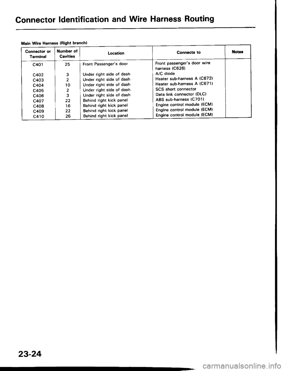
Connector ldentification and Wire Harness Routing
Main Wire Ha.ness {Right branch}
Connactor or
Terminal
Numbsr of
Caviti€sLocationConnscts tottlotor
c401
c402
c403
c404
c405
c406
c407
c408
c409
c410
,E
10
2
22
lo
22
26
Front Passenger's door
Under right side of dash
Under right side ot dash
Under right side of dash
Under right side of dash
Under right side ot dash
Behind right kick panel
Behind right kick panel
Behind right kick panel
Behind right kick panel
Front passenger's door wire
harness (C626)
A/C diode
Heater sub-harness A (C672)
Heater sub-harness A {C671}
SCS short connectol
Data link connector (DLC)
ABS sub-harness (C7011
Engine control module (ECM)
Engine control module (ECM)
Engine control module (ECMI
23-24
Page 1132 of 1413
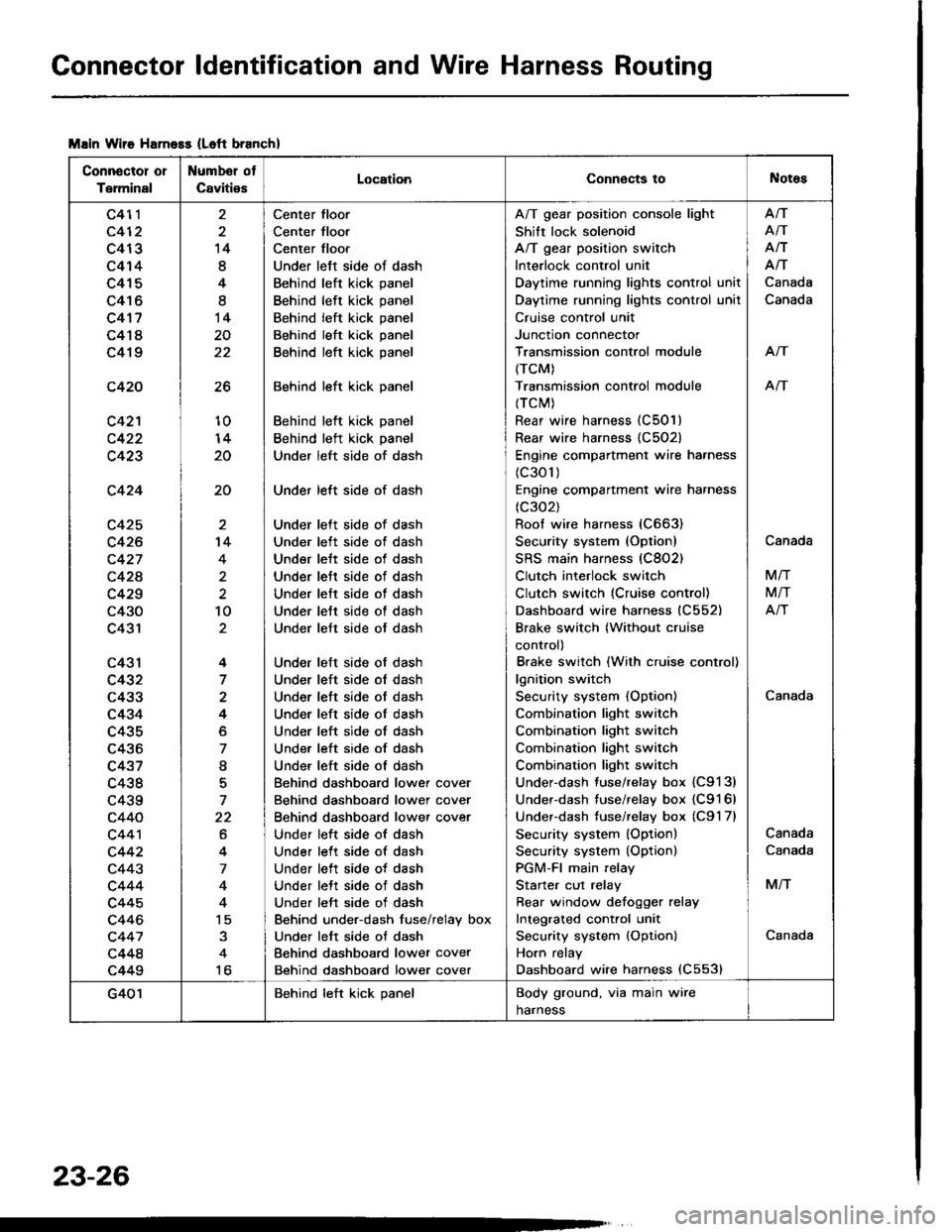
Connector ldentification and Wire Harness Routing
Msin Wiie Harness (Left branch)
Connector or
Terminal
Numbel ot
CavitiesLocationConnects toNotes
c411
c412
c413
c414
c415
c416
c4'17
c418
c419
c420
c42'l
c423
c424
c425
c426
c427
c42A
c429
c430
c431
c43l
c432
c433
c434
c435
c436
c437
c438
c439
c440
c44'l
c442
c443
c444
c445
c446
c447
c448
c449
26
10
20
20
14
8
4
I
14
20
22
't4
4
2
10
4
7
4
o
7
I
7
22
6
4
7
4
15
to
Center floor
Center floor
Center floor
Under left side ot dash
Behind left kick panel
Behind left kick panel
Behind left kick panel
Behind left kick panel
Behind left kick panel
Behind left kick panel
Behind left kick panel
Behind left kick panel
Under left side of dash
Under left side of dash
Under lett side of dash
Under left side ot dash
Under lett side of dash
Under lett side of dash
Under lett side of dash
Under lett side of dash
Under lett side ot dash
Under left side of dash
Under left side ol dash
Under left side of dash
Under left side of dash
Under left side of dash
Under left side of dash
Under left side of dash
Behind dashboard lower cover
Behind dashboard lower cover
Behind dashboard lower cover
Under left side of dash
Under left side of dash
Under left side of dash
Under lett side of dash
Under left side of dash
Behind under-dash fuse/relay box
Under left side ot dash
Behind dashboard lower cover
Behind dashboard lower cover
A/T gear position console light
Shift lock solenoid
A/T gear position switch
Interlock control unit
Daytime running lights control unit
Daytime running lights control unil
Cruise control unit
Junction connector
Transmission control module
(TCM)
Transmission controi module
{TCM)
Rear wire harness (C501)
Rear wire harness {C502)
Engine compartment wire harness
(c301)
Engine compartment wire harness
(c302)
Roof wire harness (C663)
Security system (Option)
SRS main harness (C802)
Clutch interlock switch
Clutch switch (Cruise control)
Dashboard wire harness (C552)
Brake switch (Without cruise
control)
Brake switch (With cruise control)
lgnition switch
Security system (Option)
Combination light switch
Combination light switch
Combination light switch
Combination light switch
Under-dash fuse/relay box {C9131
Under-dash fuse/relay box {C9161
Underdash tuse/relay box (C9'l 7l
Security system (Option)
Security system {Option)
PGM-FI main relay
Starter cut relay
Rear window defoqger relay
Integrated cont.ol unit
Security system {Option)
Horn relay
Dashboard wire harness (C553)
Afi
AiT
Afi
Afi
Canada
Canada
Arf
An
Canada
Canada
M/T
M/T
Atr
Canada
Canada
M/T
Canada
G401Behind left kick panelBody ground, via main wire
harness
23-26
Page 1146 of 1413
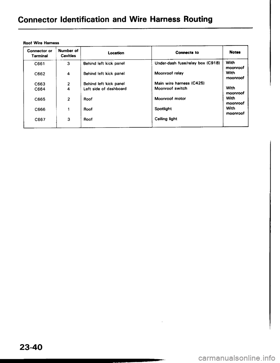
Gonnector ldentification and Wire Harness Routing
Roof Wire HanesE
Connector ol
Terminal
Number ot
CavitissLocationConnccts toNotct
c661
c662
LOOJ
c664
LOO5
LOOO
c667
4
4
2
I
Behind left kick panel
Behind left kick panel
Behind left kick panel
Left side of dashboa.d
Roof
Roof
Roof
Under-dash fuse/relay box (C918)
Moonroot relay
Main wire harnoss (C425)
Moonroof switch
Moonroof motor
Spotlight
Ceiling light
with
moonroof
with
moonroof
with
moonroof
with
moonroot
with
moonroot
23-40
Page 1150 of 1413
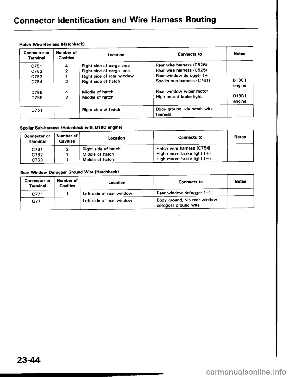
Connector ldentification and Wire Harness Routing
Hatch Wire Harnsss {Hatchbackl
Connector or
Torminal
Numbor ol
CaviliesLocationConnscts tol{otos
c751
c752
L/5J
c754
c755
4
1
4
Right side oJ cargo area
Right side of cargo area
Right side of reat window
Right side of hatch
Middle of hatch
Middle of hatch
Rear wire harness (C526)
Rear wire harness (C5251
Rear window defogger (+ I
Spoiler sub-harness (C761 )
Rear window wiper motot
High mount brake light
818C 1
engine
81 881
engine
G751Right side oJ hstchBody ground, via hatch wire
naaness
Spoilor Sub-harn6ss (Hatchback with B18C snginel
Roar Window Defoggor Ground Wire (Hatchbackl
Connoctor or
Terminal
Number ot
CavitiosLocalionConnocls toNotos
c761
c762
c763
I
1
Right side of hatch
Middle of hatch
Middle of hatch
Hatch wire harness (C754)
High mount btake light ( + )
High mount brake light ( - )
Connoctol or
Tgrminal
Numbor of
Caviti6sLocationConnoctg toNotes
c77'l1Lett side ot rear windowRear window defogger (-)
G771Left side ot rear windowBody ground, via tear window
deJogger ground wi.e
23-4r'i
Page 1152 of 1413
Connector ldentification and Wire Harness Routing
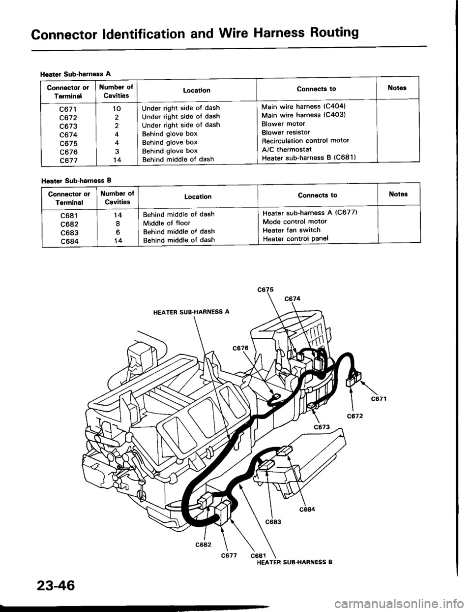
Hoator Sub-harneEs A
Hoator Sub-hameEs B
Connoctor or
Terminal
Numb€r of
CavitiesLocationConn6cts toNotog
c671
c672
c673
c674
c675
c676
c677
'lo
2
4
4
14
Under right side ot dash
Under right side of dash
Under right side of dash
Behind glove box
Behind glove box
Behind glove box
Behind middle of dash
Main wire harness (C404)
Main wire harness (C4o3)
Blower motor
Blower resistor
Recirculation control motot
A/C thermostat
Heater sub-harness B (C681)
connoctor 01
T6rminal
Number of
CavitioELocationConnocts toNotos
c681
c682
c683
c684
14
I
6
14
Behind middle of dash
Middle ol floor
Behind middle of dash
Behind middle of dash
Heater sub-harness A (C677)
Mode control motor
Heater Jan switch
Heater conttol Panel
HEATER SUB-HARI{ESS B
23-46
Page 1153 of 1413
Connector ldentification and Wire Harness Routing
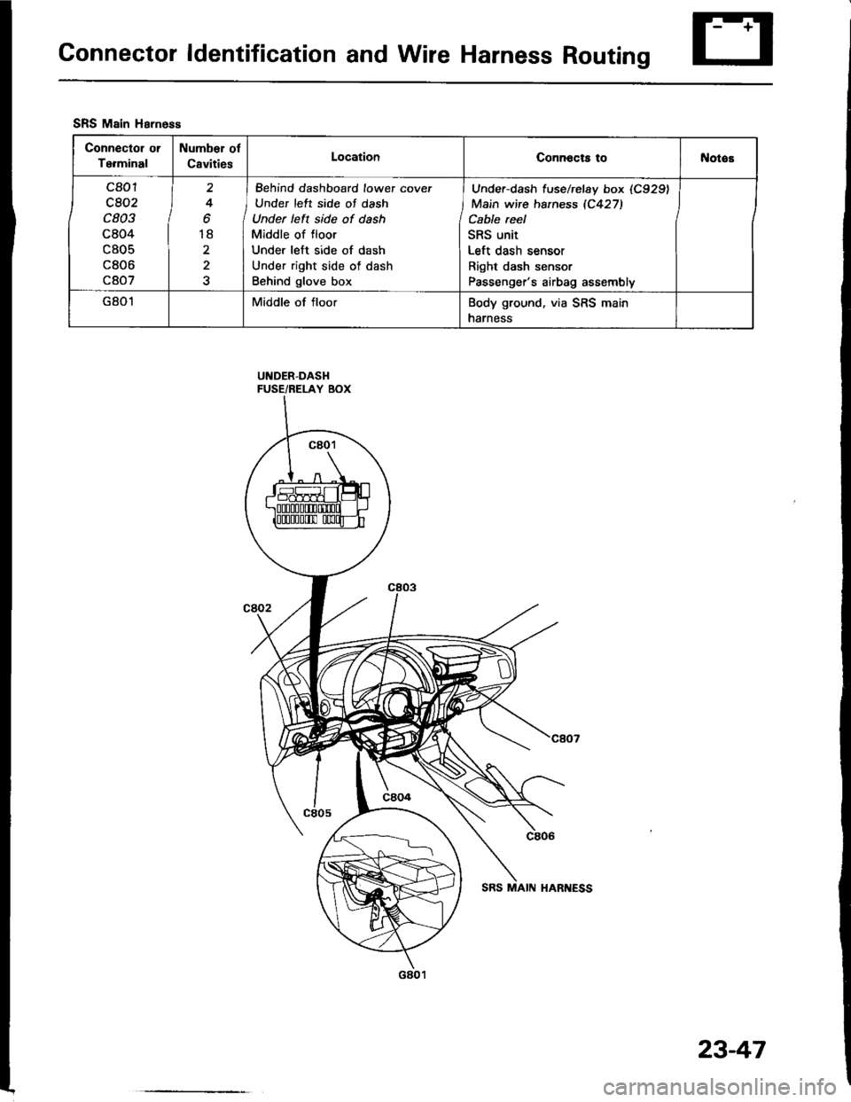
UNDER-DASHFUSE/RELAY BOX
SRS Main Harness
Connector or
Terminal
Number ol
CavitiesLocationConnocts tol{otos
c801
c802
c803
c804
c805
c806
c807
2
4
o
18
2
I Behind dashboard lowet cover
J Under left side of dash
Under left side of dash
Middle of floor
Under left side of dash
Under right side of dash
Behind glove box
Under-dash f use/rclay box (C929)
Main wire haness 1C427)
Cable reel
SRS unit
Left dash sensor
Right dash sensor
Passenger's airbag assembly
G801Middle of floorBody ground, via SRS main
harness
23-47
Page 1176 of 1413
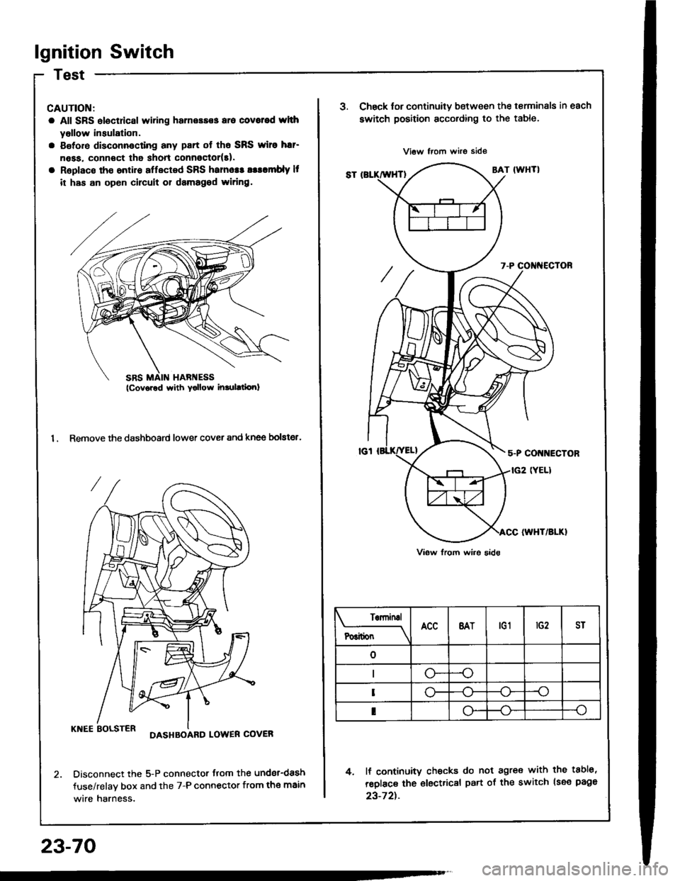
lgnition Switch
CAUTION:
a All SRS electdcal wiring harnessss aro covotod whh
yollow insulation.
a Botore disconnocting any part ot th6 SRS wiro har-
n6ss. connoct tha shon connoctor(t).
a Replac€ tho ontiro affected SRS hames! asllmbly It
it has an op6n circuit 01 damagod widng.
1. Remove the dashboard lower cover and knee bolster.
KNEE BOLSTERDASHBOARD LOWER COVER
Disconnect the 5-P connector flom the undsr-dash
fuse/relav box and the 7-P connector from the main
wire harness.
23-70
SRS MAIN HARI{ESS(Cov6red with Yollow inrulltiori)
J.Chsck tor continuity b€tween the terminals in each
switch position according to the table.
4. lf continuity checks do not agre€ with the tabl6,
reolace the €lectrical part of the switch lsee page
23-72t.
Terninal
P6itionBATtG1ST
--o
o-
I
Page 1182 of 1413
Starting System
Startel Test
NOTE: The air temDerature must be between 59 8nd
10OoF (15 and 38oC) before testing.
Recommendsd Procodure:
a Use a staner svstem tester.
a Connect and operate the equipment in accordance
with the manutacturer's instructions.
a Test and troubleshoot as described.
Altohato Procedure:
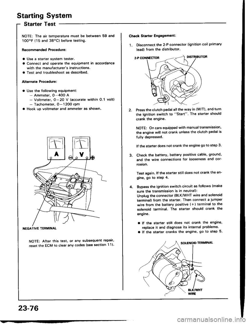
a Use the following equipment:- Ammeter. 0-4OO A- Voltmeter, O- 20 V {accurate within 0.1 volt)
- Tachometer, O- 120O rpm
a Hook up voltmeter and ammeter as shown'
NEGATIVE TERMINAL
NOTE: After this test, or any subsequent repair,
reset the ECM to clear any codes (see section 1 1)
23-76
2.
Chock Stan€r Engag6ment:
1. Disconnect the 2-P connector (ignition coil primary
lead) from the distributor.
Press the clutch pedal allthe way in (M/T), and turn
the ignition switch to "Start". The starter should
crank the engine.
NOTE: On cars equipped with manual transmission,
the engine will not crank unless the clutch pedal is
fully depressed.
lf the staner does not crank the engine go to step 3.
Check the baftery, battery positive cable, ground,
and the wire connections for looseness and cor-
rosion,
Test again. lf the starter still does not crank the en-
gine, go to step 4.
Bvpass the ignition switch citcuit as follows {make
sure the transmission is in neutral):
Unplug the connector (BLK/WHT wire and solenoid
terminsl) trom the starter. Then connect a jumper
wire from the battery positive ( + ) terminal to the
solenoid terminal. The starter should crank the
engrne.
a lf the starter still does not crank the engine,
replace it and diagnose its internal problems.
a lf the starter cranks the engine, go to step 5.
J.
4.
Page 1195 of 1413
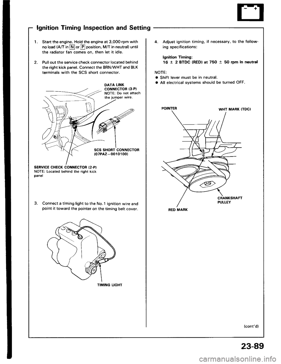
lgnition Timing Inspection and Setting
1.Start the engine. Hold the engine at 3,00O rpm with
no load (A/T in S or E position, M/T in neutral) until
the radiator fan comes on, then let it idle.
Pull out the service check connector located behind
the right kick panel. Connect the BRN/WHT and BLK
terminals with the SCS short connector.
4. Adiust ignition timing, if necessary, to the follow-
ing specifications:
lgnition Timing:
16 t 2 BTDC (RED) at 75O 1 50 rpm in noutral
NOTE:
a Shift lever must be in neutral.
a All electrical systems should be turned OFF.DATA LINKCONNECTOR {3-P}NOTE: Do not attachthe jumper wire.
POINTER
SCS SHORT CONNECTOR{0?PAZ-O010't 00t
SERVICE CHECK CONNECTOR I2.PINOTE: Located behind the right kickoanel
Connect a timing light to the No.1 ignition wire andpoint it toward the pointer on the timing belt cover.
TIMING LIGHT
lcont'd)
REO MARK
23-89
Page 1197 of 1413
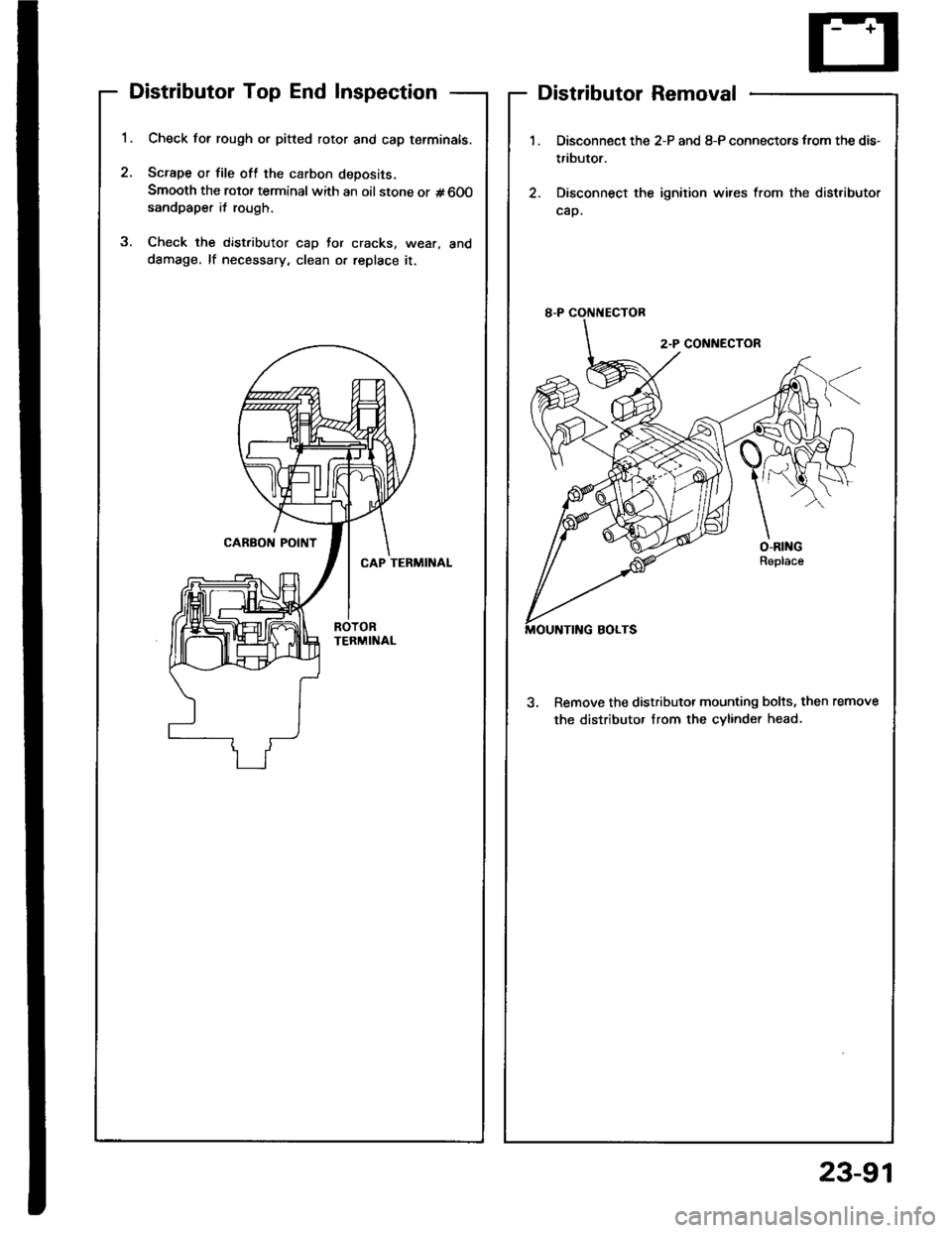
Distributor Top End Inspection
1.
2.
Check for rough or pitted rotor and cap tefminals.
Scrape or file oft the carbon deposits.
Smooth the rotor terminal with an oil stone or #600sandpaper i{ rough.
Check the distributor cap Jor cracks, wear, and
dSmage, lf necessary, clean or replace it.
2
Distributor Removal
1.
2.
Disconnect the 2-P and 8-P connectors from the dis-
tributor.
Disconnect the ignition wires from the distributor
cap.
3. Remove the distributor mounting bolts, then remove
the distributor Irom the cvlinder head.
23-91