HONDA INTEGRA 1994 4.G Workshop Manual
Manufacturer: HONDA, Model Year: 1994, Model line: INTEGRA, Model: HONDA INTEGRA 1994 4.GPages: 1413, PDF Size: 37.94 MB
Page 421 of 1413
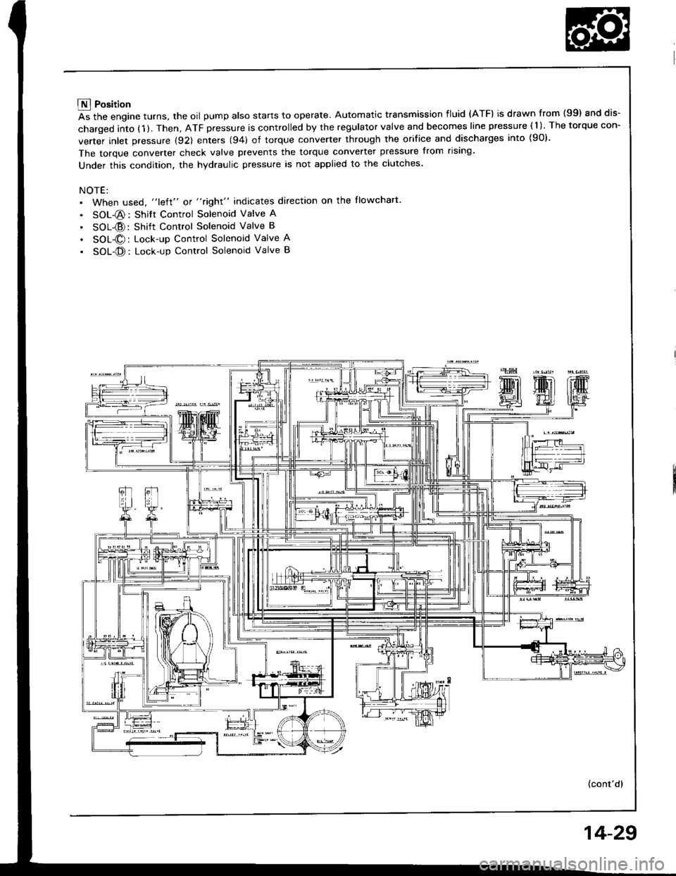
E Position
As the engine turns, the oil pump also starts to operate. Automatic transmission fluid (ATF) is drawn from (99) and dis-
charged into (1 ). Then, ATF pressure is controlled by the regulator valve and becomes line pressure ( 1 ). The torque con-
verter inlet pressure (92) enters (94) of torque converter through the orifice and discharges into {90}.
The torque converter check valve prevents the torque converter pressure from rising'
Under this condition, the hydraulic pressure is not applied to the clutches.
NOTE:. When used, "left" or "right" indicates direction on the llowchart
. SOL-@: Shift Control Solenoid Valve A
' SOL{D:Shift Control Solenoid Valve B
. SOL@: Lock-up Control Solenoid Valve A
. SOL-@: Lock-up Control Solenoid Valve B
(cont'd)
14-29
Page 422 of 1413
Description
Hydraulic Flow (cont'd)
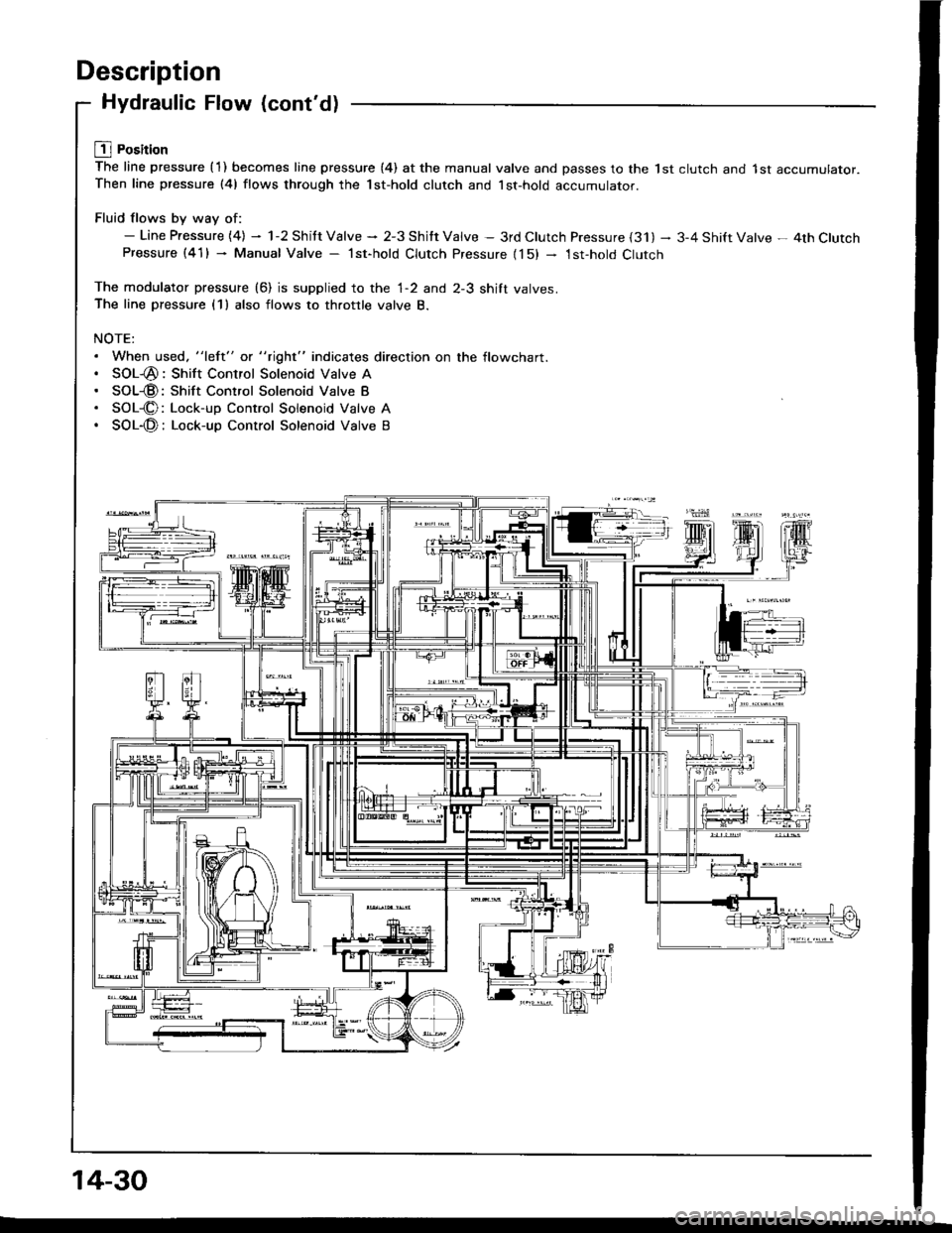
L1l Position
The line pressure {1) becomes line pressure (4) at the manual valve and passes to the lst clutch and 1st accumulator.Then line pressure (41 flows through the 1st-hold clutch and lst-hold accumulator.
Fluid flows by way of:- Line Pressure {4} - 1-2 Shitt Valve * 2-3 Shitt Valve - 3rd Clutch Pressure {31) - 3-4 Shift Valve - 4th ClutchPressure (41) - Manual Valve - lst-hold Clutch Pressure {15) - 1st-hold Clutch
The modulator pressure (6) is supplied to the 1-2 and 2-3 shift valves.The line pressure (1) also flows to throttle valve B.
NOTE:. When used. "left" or "right" indicates direction on the flowchart.. SOL-@: Shift Control Solenoid Valve A. SOL@: Shift Control Solenoid Valve B. SOL-@: Lock-up Control Solenoid Valve A. SOL-@: Lock-up Control Solenoid Valve B
14-30
Page 423 of 1413
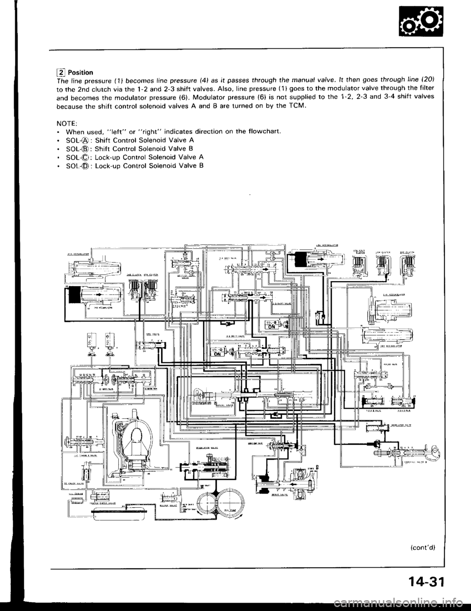
f4 Position
ihe line pressure (11 becomes line pressure (41 as it passes through the manual valve.lt then goes through line l2O)
to the 2nd clutch via the 1-2 and 2-3 shift valves. Also, line pressure (1 ) goes to the modulator valve through the filter
and becomes the modulator pressure (6). Modulator pressure (6) is not supplied to the 1-2, 2-3 and 3-4 shift valves
because the shitt control solenoid valves A and B are turned on by the TCM.
NOTE:. When used, "left" or "right" indicates direction on the flowchart
. SOL-@: Shift Control Solenoid Valve A
. SOL-@: Shilt Control Solenoid Valve B
. SOL-O: Lock-up Control Solenoid Valve A
. SOt -@ : Lock-up Control Solenoid Valve B
(cont'd)
14-31
Page 424 of 1413
Description
Hydraulic Flow (cont'dl
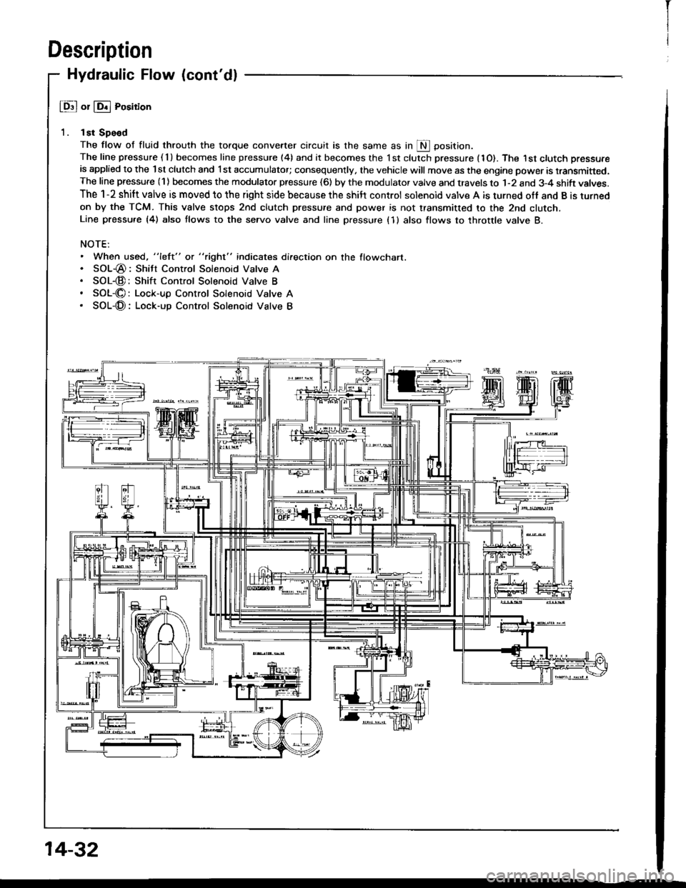
@ or @ Position
1. lst Spe€d
The flow of fluid throuth the torque convener circuit is the same as in S Oosition.The line pressure ( 1 ) becomes line pressure (4) and it becomes the 1 st clutch pressure (1O). The I st ctutch pressure
is applied to the lst clutch and l st accumulator; consequently, the vehicle will move as the engine power is transmitted.The line pressure (1) becomes the modulator pressure (6) by the modulator valve and travels to 1-2 and 3-4 shift valves.
The 1-2 shift valve is moved to the right side because the shilt control solenoid valve A is turned off and B is turned
on by the TCM. This valve stops 2nd clutch pressure and power is not transmitted to the 2nd clutcn.Line pressu.e {4) also tlows to the seryo valve and line pressure (1 } also flows to throttle valve B.
NOTE:. When used, "left" or "right" indicates direction on the flowchart.. SOL-@: Shitt Control Solenoid Valve A. SOL-@:Shift Control Solenoid Valve B. SOL-O: Lock-up Control Solenoid Valve A. SOL-@: Lock-up Control Solenoid Valve B
14-32
I
Page 425 of 1413
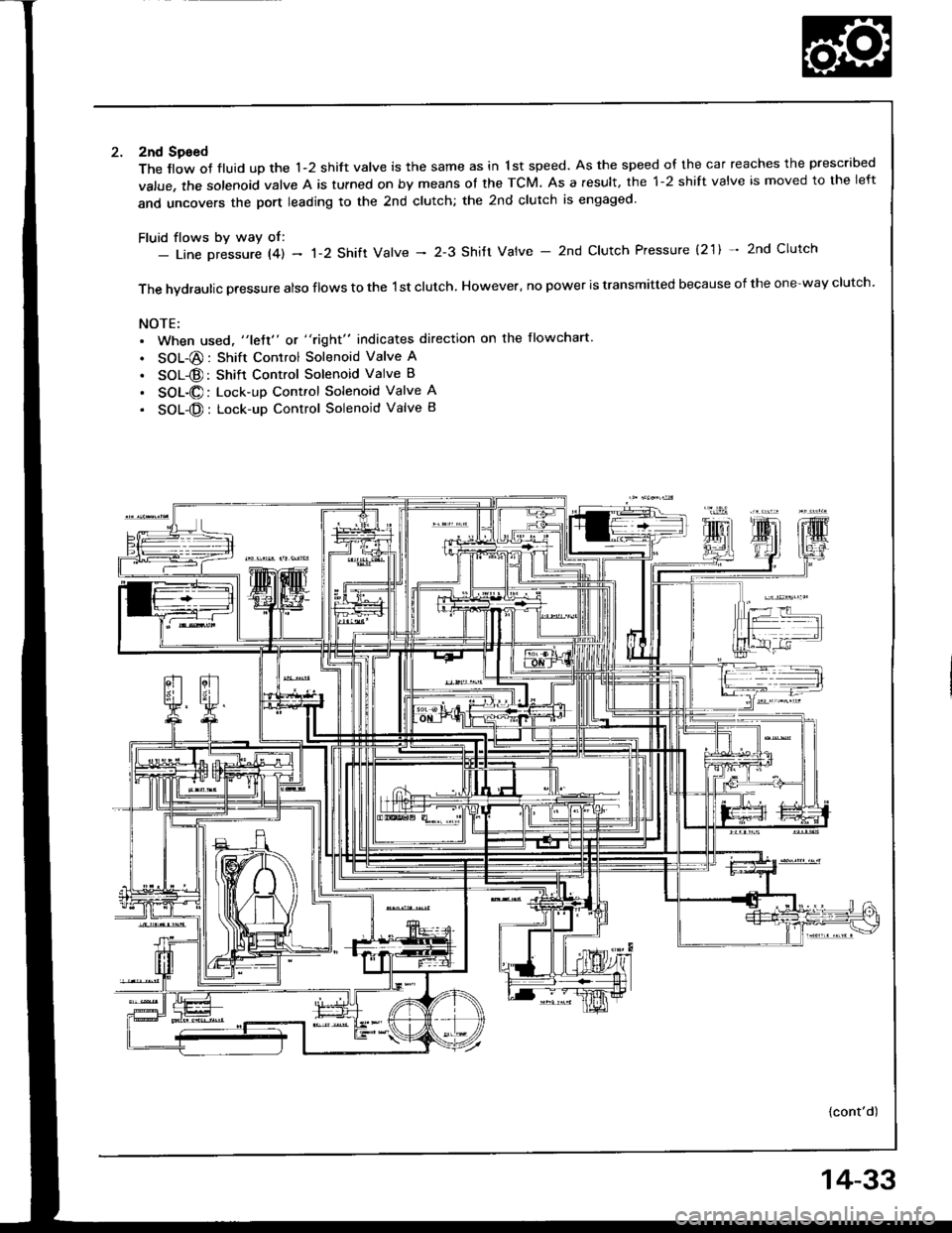
2nd Sgeed
The llow of fluid up the 1-2 shift valve is the same as in 1st speed. As the speed of the car reaches the prescribed
value, the solenoid valve A is tulned on by means ot the TCM. As a result, the 1-2 shift valve is moved to the left
and uncovers the port leading to the 2nd clutch; the 2nd clutch is engaged'
Fluid flows by way of:- Line Dressure l4l - 'l-2 Shift Valve - 2-3 Shitt Valve - 2nd Clutch Pressure (2'1) * 2nd Clutch
The hvdraulic pressure also flows to the 1st clutch, However, no power is transmitted because of the one-way clutch.
NOTE:. When used, "lett" or "right" indicates direction on the flowchart
. SOL-@: Shift Control Solenoid Valve A
. SOL@: Shift Control Solenoid Valve B
. SOL-@: Lock-up Control Solenoid Valve A
. SOL-@: Lock-up Control Solenoid Valve B
{cont'd)
14-33
Page 426 of 1413
Description
Hydraulic Flow (cont'd)
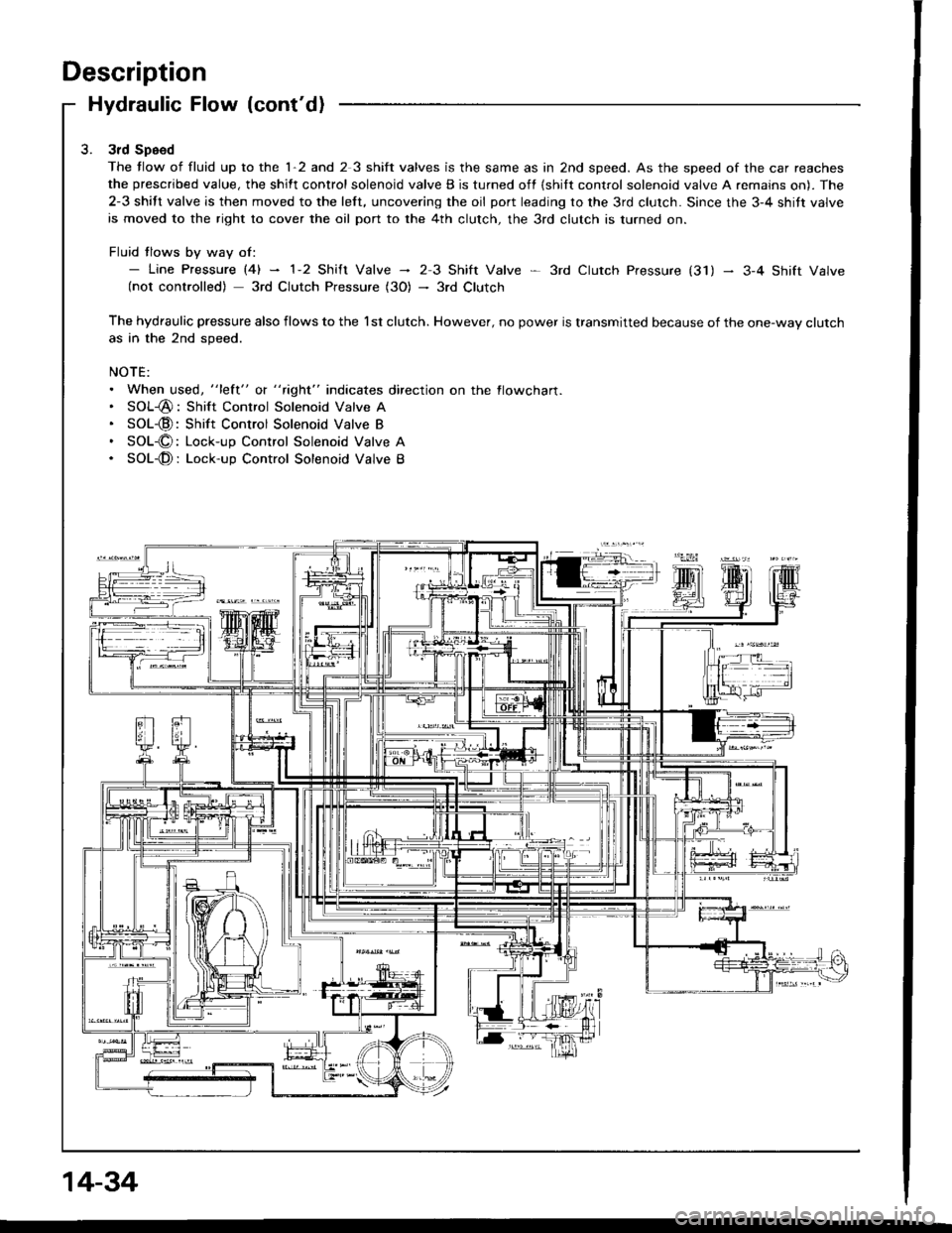
3rd Speed
The tlow of fluid up to the 1-2 and 2 3 shift valves is the same as in 2nd speed. As the speed of the car reaches
the prescribed value, the shift control solenoid valve B is turned off {shilt control solenoid valve A remains on). The
2-3 shift valve is then moved to the left, uncovering the oil port leading to the 3rd clutch. Since the 3-4 shitt valve
is moved to the right to cover the oil port to the 4th clutch, the 3rd clutch is turned on.
Fluid tlows by way of:- Line pressure l4l - 1-2 shift valve - 23 Shift Valve * 3rd ctutch pressure (31) - 3-4 shift valve(not controlled) 3rd Clutch Pressure (3O) - 3rd Clutch
The hydraulic pressure also flows to the l st clutch. However, no power is transmitted because of the one-way clutchas in the 2nd speed.
NOTE:. When used, "lett" o( " tight" indicates direction on the flowcharl.. SOL-@: Shift Control Solenoid Valve A. SOL-@:Shift Control Solenoid Valve B. SOL-O: Lock-up Control Solenoid Valve A. SOL-@: Lock-up Control Solenoid Valve B
14-34
Page 427 of 1413
Lq4 Position
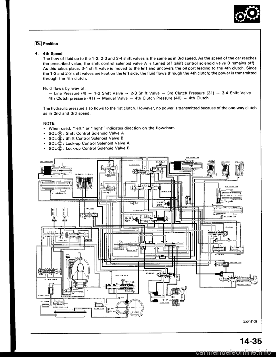
4. 4th Spe6d
The flow of tluid up to the 1-2, 2-3 and 3-4 shift valves is the same as in 3rd speed. As the speed of the car reaches
the prescribed value, the shift control solenoid valve A is turned oJt (shift control solenoid valve B remains off).
As this takes place, 3-4 shift valve is moved to the left and uncovers the oil port leading to the 4th clutch. Since
the 1-2 and 2-3 shift valves are kept on the left side, the fluid flows through the 4th clutch; the power is transmitted
through the 4th clutch.
Fluid flows by way of:- Line Pressure l4l - 'l'2 Shift Valve -t 2-3 Shitt Valve - 3rd Clutch Pressure (31) - 3-4 Shift Valve
4th Clutch pressure (41) - Manual Valve 4th Clutch Pressure {4O) - 4th Clutch
The hvdraulic pressure also tlows to the '1st clutch. However, no power is transmitted because of the one-way clutch
as in 2nd and 3rd soeed.
NOTE:. When used, "left" or "right" indicates direction on the flowchan.
. SOL-@: Shitt Control Solenoid Valve A
. SOL-@: Shift Control Solenoid Valve B
. SOL-O: Lock-up Control Solenoid Valve A
. SOL-@: Lock-up Conttol Solenoid Valve B
(cont'dl
14-35
Page 428 of 1413
Description
Hydraulic Flow (cont'd)
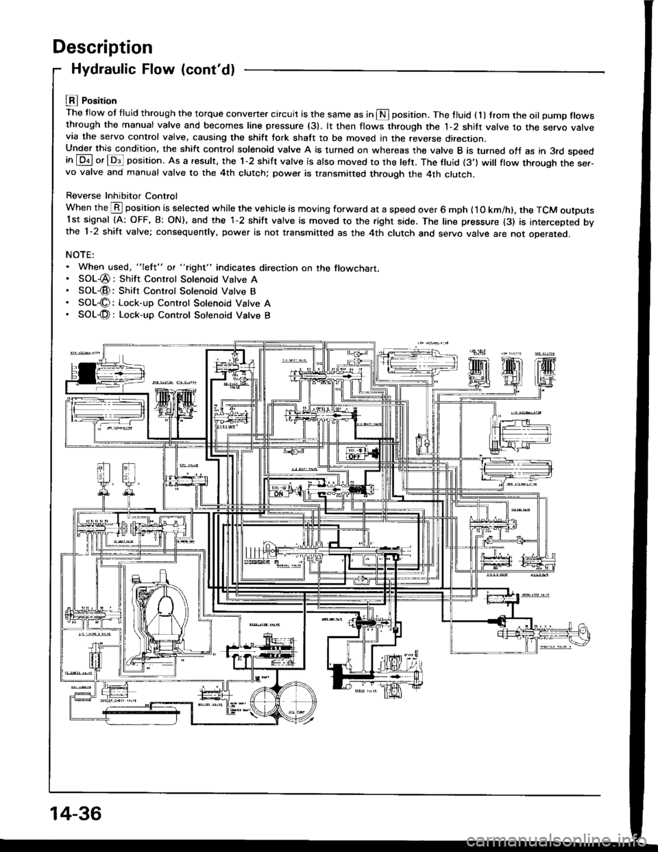
LEI Position
The flow ot fluid through the torque convener circuit is the same as in S position. The tluid ( 1 ) trom the oil pump flowsthrough the manual valve and becomes line pressure (31. lt then flows through the 1-2 shift valve to the servo varvevia the servo control valve, causing the shift tork shatt to be moved in the reverse direction.Under this condition, the shift control solenoid valve A is turned on whereas the valve B is turned ofJ as in 3rd speedin [Dil or lDs]l position. As a result, the 1-2 shift valve is also moved to the left. The ftuid (3'] will ftow through the ser-vo valve and manual valve to the 4th clutch; power is transmitted through the 4th clutch.
Reverse Inhibitor Control
When the @ position is selected while the vehicle is moving forward at a speed over 6 mph ( 1O km/h). the TCM outputs1st signal (A: OFF, B: ON), and the 1-2 shift valve is moved to the right side. The line pressure {3) is intercepted bvthe 1-2 shift valve; consequently, power is not transmitted as the 4th clutch and servo valve are not oDerareo.
NOTE:. When used, "lefl" ot "tight" indicates direction on the flowchart.. SOL-@: Shift Control Solenoid Valve A. SOL€: Shift Control Solenoid Valve B. SOL€: Lock-up Control Solenoid Vatve A. SOL-@: Lock-up Control Sotenoid Vatve B
14-36
Page 429 of 1413
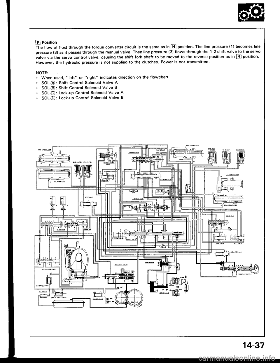
Lll Position
The flow of fluid through the torque converter circuit is the same as in I position. The line pressure ( l ) becomes line
pressure (3) as it passes through the manual valve. Then line pressure (3) flows through the 1-2 shift valve to the servo
valve via the servo control valve. causing the shift fork shaft to be moved to the reverse position as in E position.
However. the hydraulic pressure is not supplied to the clutches. Power is not transmitted.
NOTE:. When used, "left" or "right" indicates direction on the flowchart.
. SOL-@: Shitt Control Solenoid Valve A
. SOL-@: Shift Control Solenoid Valve B
. SOL-O: Lock-up Control Solenoid Valve A
. SOL-O: Lock-up Control Solenoid Valve B
14-37
Page 430 of 1413
Description
Lock-up System
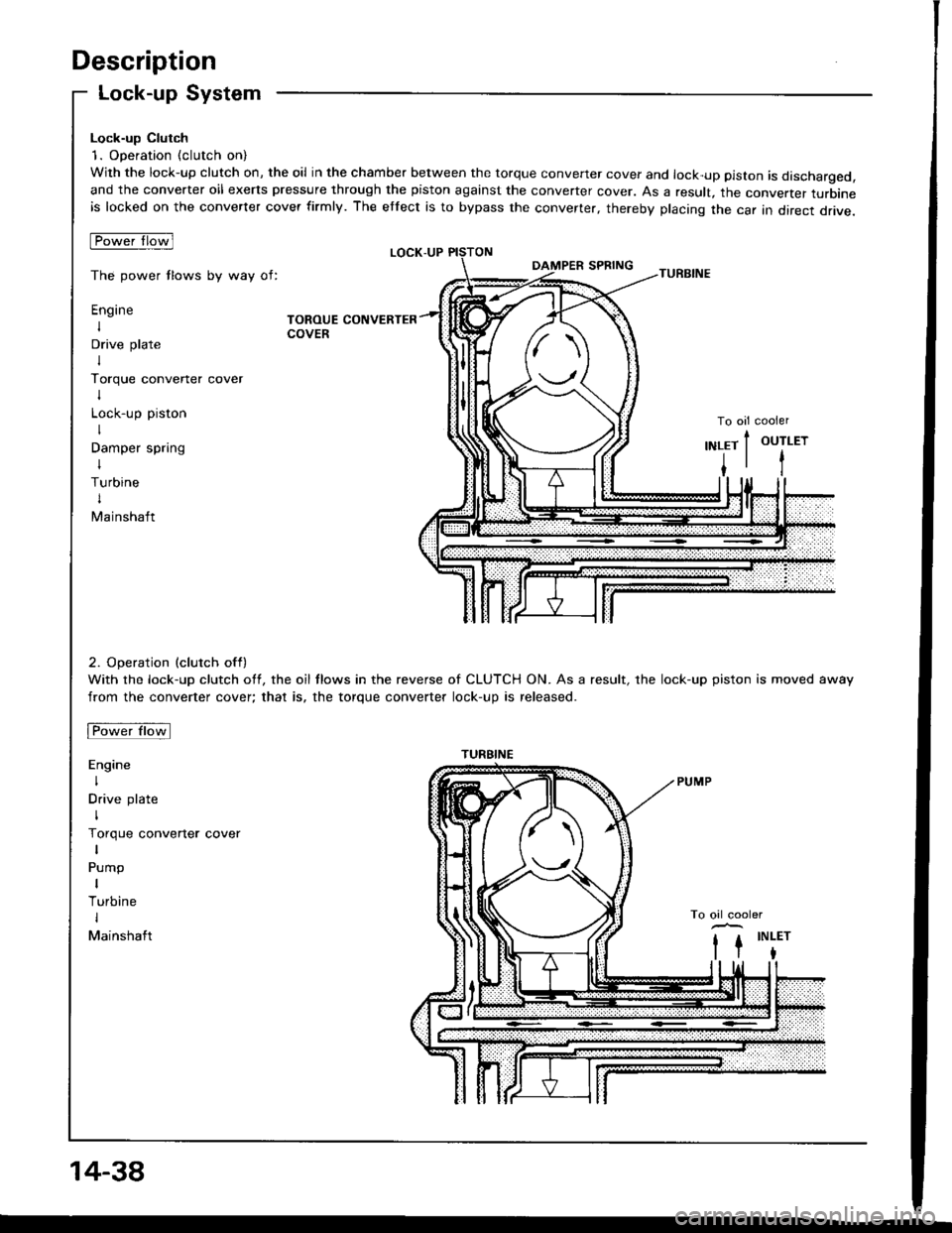
Lock-up Clutch
1. Operation (clutch on)
With the lock-up clutch on, the oil in the chamber between the torque convener cover and lock-up piston is discharged,and the converter oil exerts pressure through the piston against the converter cover. As a result, the converter turbineis locked on the converter cover firmly. The etfect is to bypass the converter, thereby placing the car in direct drive.
tpowefJlo-wl
The power tlows by way of:
Engine
I
Drive plate
I
Torque convener cover
I
Lock-up piston
I
Damper spring
I
Turbine
t
Mainshaft
TOROUE CONVERTERCOVER
LOCK-UP
TURBINE
To oil cooler
2. Operation (clutch off)
With the lock-up clutch off, the oil tlows in the reverse of CLUTCH ON. As a result, the lock-up piston is moved away
from the converter cover; that is, the torque converter lock-up is released.
Fowtttowl
Engine
I
Drive plate
I
Torque converter cover
Pump
I
Turbine
I
Mainshaft
OUTLET
t
,\
TURBINE
14-38