indicator HONDA INTEGRA 1994 4.G Service Manual
[x] Cancel search | Manufacturer: HONDA, Model Year: 1994, Model line: INTEGRA, Model: HONDA INTEGRA 1994 4.GPages: 1413, PDF Size: 37.94 MB
Page 448 of 1413
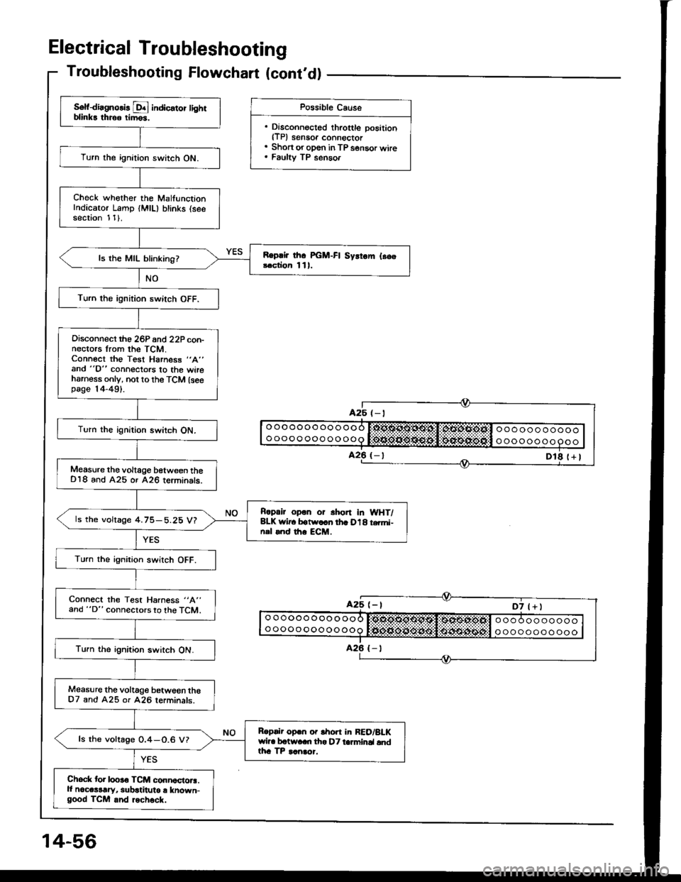
Troubleshooting Flowchart (cont'd)
Sof{irgnolis D! indic€tor tightblinks throo rim6s.
Turn the ignition switch ON.
Check whother the MalfunctionIndicator Lamp (MlL) blinks (seesection 1 1).
Replir thc PGM-FI Syrtom l.s.!.ction 111.ls the MIL blinking?
Turn the ignition switch OFF.
Oisconnect rho 26P 6nd 22P con-nectors lrom the TCM.Connect the Test Harness "A"
and "D" connectors to the wireharness only, not to the TCM lseepage |4-491.
Turn the ignition switch ON.
Measure the voltage between theDl8 and A25 or A26 teiminats.
Rcpalr opon or shon In WHT/BLK wlr. botw.cn th. D18 t.mi-nsl rnd th. ECM.
ls the voltage 4.75-5.25 V?
Turn the ignirion swirch OFF.
Connect the Test Harness "A"
and "D" connectors to the TCM.
Turn the ignition switch ON.
Measure the voltage betwe€n theD7 and A25 or 426 rerminals.
Roprlr oprn o. lhon in RED/BLKwil. botwaan tha DT ta]minal andtha TP ranaor.
ls the voltage 0.4-0.6 V?
Chock tor looro TCM connoctora.ll noce$rry, subatitulo r known-good TCM and rechock.
Possible Cause
. Disconnocted throttle position{TP) sensoa connoctor. Short or oDen in TP s€nsor wire. Faulty TP senaor
Page 450 of 1413
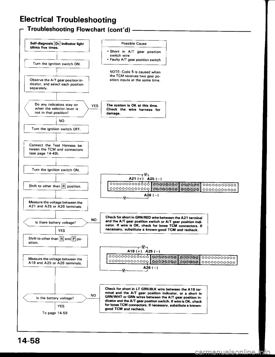
Electrical Troubleshooting
Troubleshooting Flowchart lcont'dl
Possible Cause
'Short in A/T gear posilionswitch wire. Faulty A/T gear position switch
NOTE: Code 5 is caused whenthe TCM receives two gear po-sition inputs at the same time.
Or425 t- |
-l@r
A19l+) A25 (-)
YES
14,59
Solt-diagno8is l!4 indicato. tightblinks fiv6 timos.
Turn the ignition switch ON.
Observe the A/T gear position in-dicator, and select each positionseparately.
Do any indicators stay onwhen the selector lever isnot in that position?
The systom is OK ai this timo.Ch.ck tho wiro ha|noss toroamago.
Turn the ignition switch OFF.
Connect the Test Harness be,tween the TCM and connectors{see page 14-49}.
Turn the rgnition switch ON.
Shilt to other than E position.
Measure the voltage b€tween theA21 and A25 or 426 terminats.
Chock for short in GRN/RED wi.o botwoon tho A2t torminaland th6 A/T goar po6ition swirch or A/T 96ar posirion indi-cator. lf wire is OK, chock for loo8o TCM connocioF. lfnecassary, subatituto a known-good TCM and rochsck.
Measure the voltage between the419 and A25 or 426 terminals.
Ch6ck for 6hon in LT GRN/BLK wi.e borwoon tho A19 tor-minal and tho A/T goar position indicato., o. a shon inGRN/WHT or GRN wiros botwson tho A/T goa. position in-dicato. and tho A/T goa. position swhch. ll wire is OK. chockfor looso TCM connactoE. lf nocos$sry, substituto a known-good TCM and .ech6ck,
ls the battery voltage?
14-58
To page
Page 451 of 1413
14-58
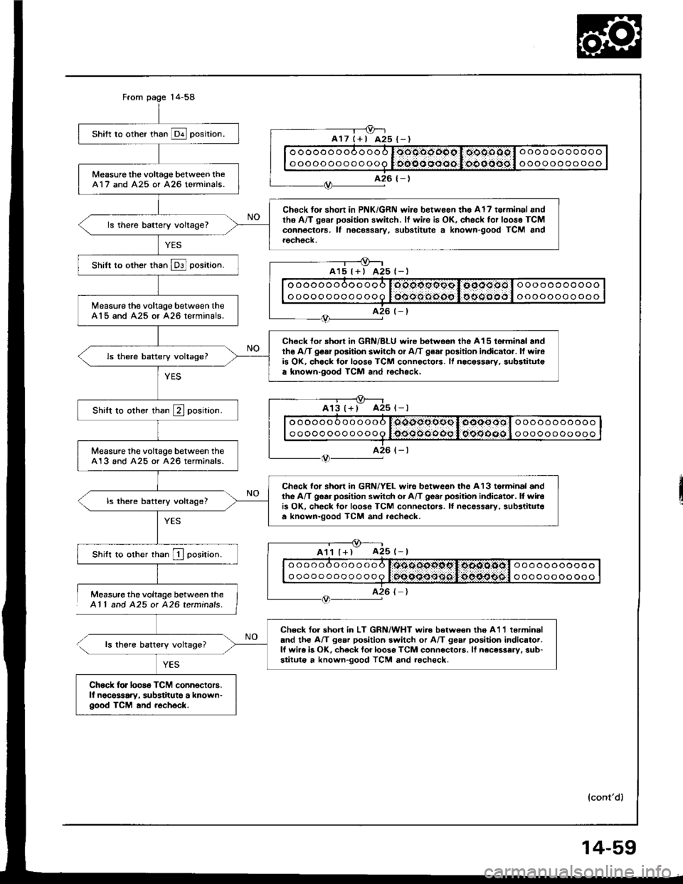
Measure the voltage between theAl l and 425 ot 426 tetminals.
ls thgre battery voltage?
YES
shift ro other than E posirion.
Measure the voltage belween lheA17 and A25 or A26 terminals.
Chock to. short in PNK/GRN wire betwoon tho Al7 torminal andth6 A/T gsar position switch. It wire is OK, chsck for looso TCMconnoctors. lf nocessary, substitute a known-good TCM androch€ck.
ls there battery voltage?
Shifi to other than E] position.
Measure the voltage between theA15 and A25 or 426 terminals.
Chock for short in GRN/BLU wire betweon the A15 terminal andthe A/T gosr position switch or A/T g€a. position indicato.. ll wirois OK, chock for loose TCM connectors. ll nocessary, substitulsa known-good TCM and rochock.
ls there battery voltage?
Shilt to other than E position.
Measure the voltage between theA13 and A25 or 426 terminals.
Chock for short in GRN/YEL wire betweon ths A13 torminal andthe A/T gear position switch or A/T gear posilion indicator. l{ wirois OK, check lor loose TCM connectors. lI necessarv, substitutaa known-good TCM and rechsck.
ls there battery voltage?
Shift to other rhan I oosirion.
Chock tor shon in LT GRN/WHT wi.e b€twoan th6 A1'l lerminaland the A/T gear position switch or A/T gear position indicator.lf wira b OK, ch6ck foi loose TCM conneclors. lf noc€ssary, sub-stituto a known-good TCM and rocheck.
Chock for looso TCM conn€ctors.lf noce$ary, substitute a known-good TCM and recheck.
oooooooooooo
oooooooooooo
ooooooooooo
oooooooo ooo
ooooooooooo
ooooooooooo
oooooooooooo
oooooooooooo
oooooooooooo
oooooooooooo
ooooooooooo
ooooooooooo
ll
{cont'd)
14-59
Page 452 of 1413
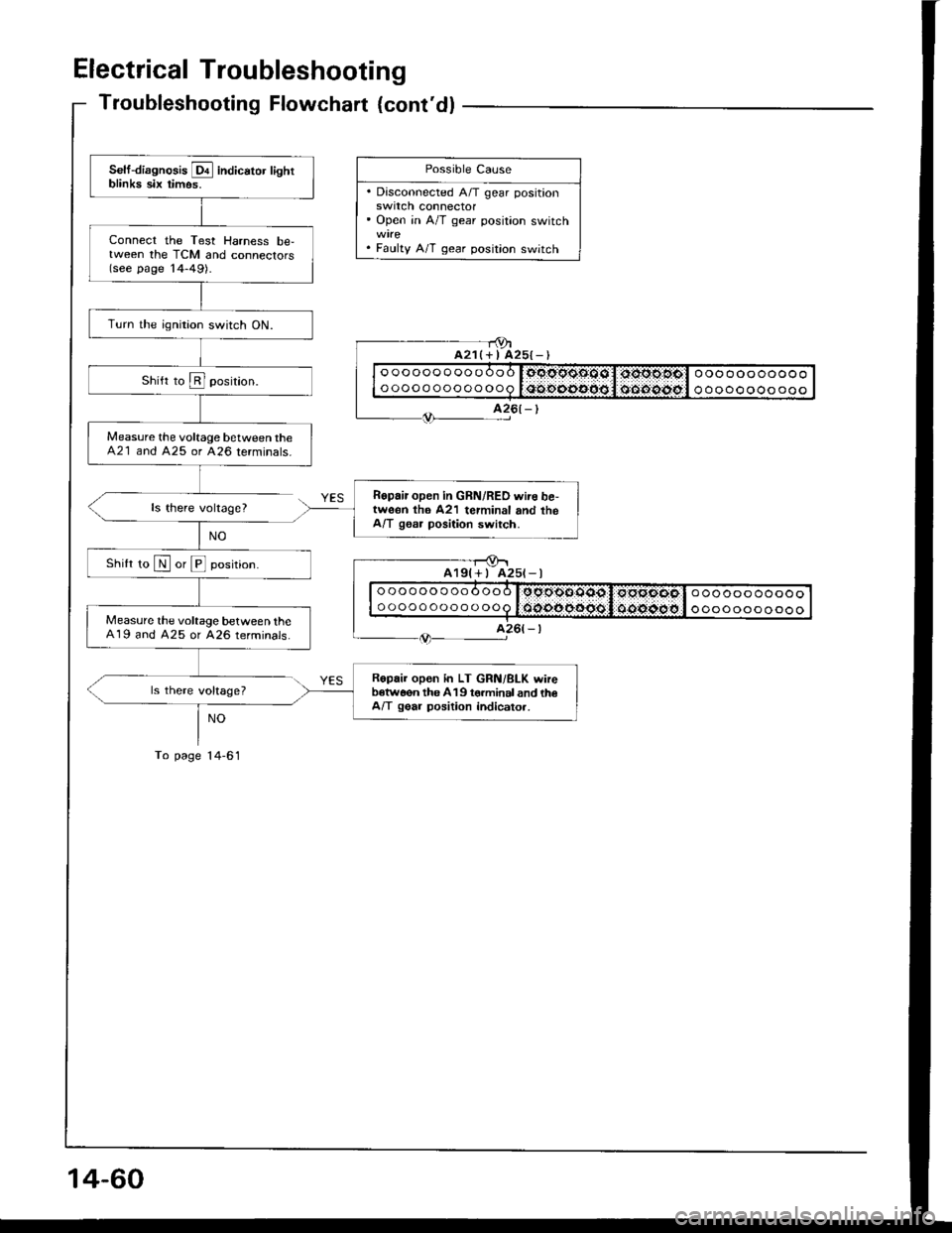
Electrical Troubleshooting
Troubleshooting Flowchart {cont'dl
ls there voltage?
ls there voltage?
NO
To page l4-61
- - r9ta21(+ I A25{-)
Self-diagnosis E indicator lightblinka six timos.
Connect the Test Harness be,tween the TCM and connectors(see page '14-49).
Turn the ignition switch ON.
Measure the voltage between theA21 and 425 or 426 terminals.
Ropair open in GRN/RED wire be,tweon th6 A21 terminal and theA/T gssr position switch.
Shilt ro N or E position.
Measure the voltage between theA19 and A25 or A26 terminals.
Ropair open in LT GRN/BLK wireb€tw6on the 419 torminal and th€A/T gear position indicato..
Possible Cause
. Disconnected A/T gear positionswrtcn connector' Open in A/T gear position switch
. Faulty A/T gear position switch
oooooooooooo
ooooooooooooooooooooooo
ooooooooooo
A25t-l
oooooooooooo
ooooooooooooooooooooooo
ooooooooooo
14-60
Page 454 of 1413
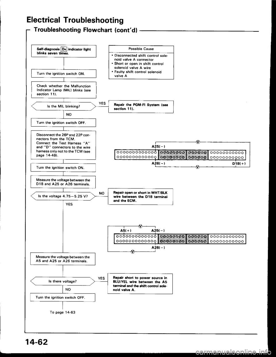
Electrical Troubleshooting
S€ltdiagno3b Lql indicaror lighrblinks sovon timgs.
Turn the ignition switch ON.
Check whether the MalfunctionIndicator Lamp {MlL) blinks (seesection 11).
Ropai lhe PGM-FI Sysrem (so€Bection 1 11,ls the MIL blinking?
Turn th6 ignition switch OFF.
Disconnect the 26P and22P con-nectors from the TCM.Connect the Test Harness "A"
and "D" connectors to the wireharness only not to the TCM (seepage 14-49).
Turn the ignition switch ON.
Measure the voltage betw€€n theD18 and A25 or A26 lerminals.
Repair opon o. sho.t in WHT/BLKwire botwoon th€ D18 tarminaland the ECM.
fs the voftage 4.75-5.25 V?
Measure the voltage between theA5 and A25 or A26 terminals.
Ropair lhon to powor sourc6 inBLU/YEL wiro botwoon the A5torminal and th6 lhift control solo-noid valve A.
Turn the ignition switch OFF.
Troubleshooting Flowchart (cont'dl
Dl8( r I
Possible Cause
. Discohnected shift control sole-noid valve A connector. Short or open in shift controlsolenoid valve A wire. Faulty shill control solenoid
ooooooooooooooooooooooo
ooooo oooooooa t:tJio*ie*O:lt$!l $4lrulitEijt'l o oo oooooooo
Page 456 of 1413
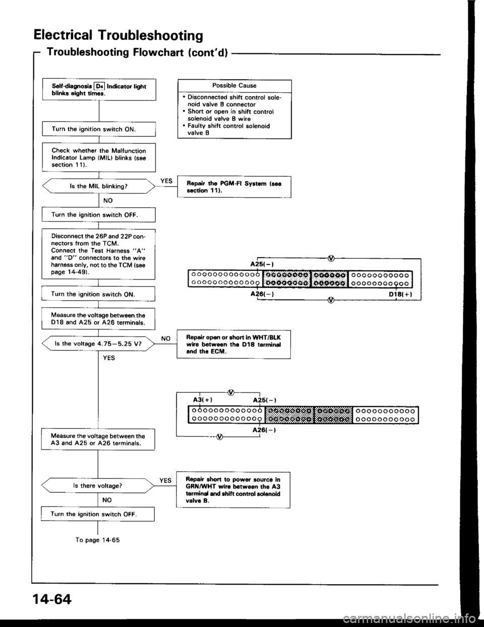
Electrical Troubleshooting
Troubleshooting Flowchart (cont'dl
Possible Cau6e
. Disconnected shift control sole-noid valve B connector. Short or open in shift controlsolenoid valve B wire. Faulty shilt control solenoidvalve B
Solfdiagnolir [!4 Indicato. lightbllnk! eight tim6r.
Turn the ignition switch ON.
Check whother the MalfunctionIndicator Lamp {MlL) blinks (seesection I 11.
Rcpsir rho FGM-FI Syrtem lso6scciion l1l.ls the MIL blinking?
Turn the ignition swirch OFF.
Oisconn€ct the 26P and 22P con-nectors trom the TCM.Connect the Test Harness "A"
and "D" connectors to the wirohamess only. not to the TCM {sesp6ge 14-49).
Turn the ignition switch ON.
Measure the voltage betwe€n theD18 and A25 or A26 terminals.
Ropeir opon or short in WHT/BLKwiro trotweon th6 D18 termineland tho EcM.
ls the voltage 4.75-5.25 V?
Measure the voltage between th€A3 and A25 or A26 terminals.
Ropair rhort to powor rourco inGR /WHT wir6 b€twgan tho A3tormirEl and shift conLol lolonoidvalve B.
Turn the ignition switch OFF.
A2s( - |
DlA( + I
o oooooooooo
ooooooooooooo oo ooo ooooo
oooo o o oo
To page
Page 458 of 1413
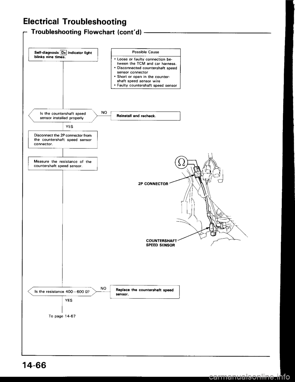
Electrical Troubleshooting
Troubleshooting Flowchart {cont'dl
ls the countershaft speedsensor installed properly
2P CONNECTOR
COUNTERSHAFTSPEED SENSOR
Possible Cause
. Loose or faulty connection be-rween the TCM and car harness.. Disconnected countershaft speedsensor connector. Short or open in the counter-shatt speed sensor wire. Faulty counlershaft speed sensor
Self-diagnosis Lq! indicator lighrblinks nino timos.
Disconnect the 2P conneclor lromthe countershaft speed sensorconnector,
Measure the resistance ot theco!ntershaft speed sensor.
ls the resistance 4OO 600 0?
To page 14-67
14-66
Page 460 of 1413
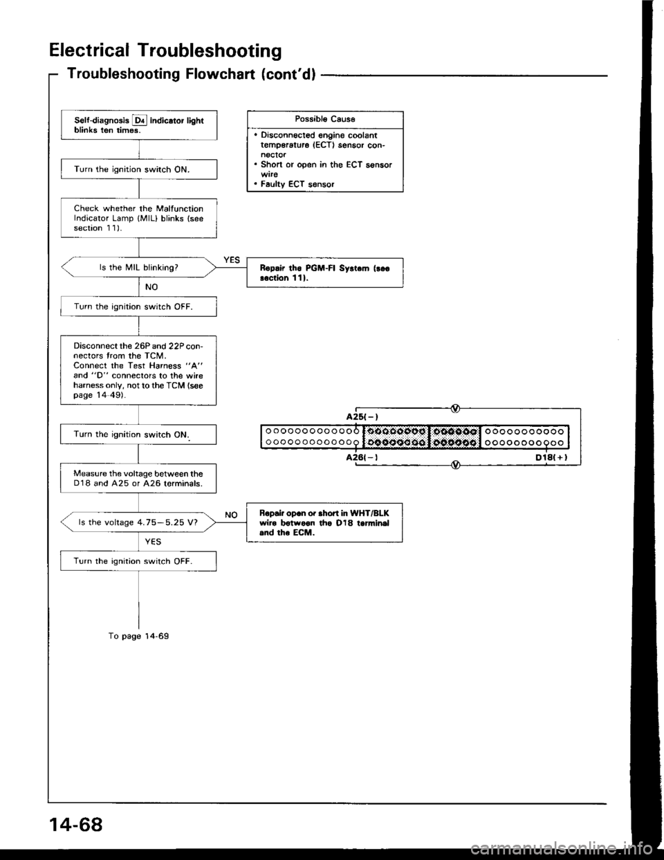
Electrical Troubleshooting
Troubleshooting Flowchart (cont'dl
Possibl€ Caus6
. Disconnoct€d engine coolantt€mp€rature (ECTI sensor con-noctor. Short or open in the ECT sensor
. Faulty ECT s€nsor
Self-diagnosis E indicator lightblinks ten times.
Turn the ignition switch ON.
Check whether the MalfunctionIndicator Lamp {MlL} blinks (seesection 1 1)-
ls the MIL blinking?Rop.ir tho PGM-FI Syrt.m (!go
!.ction 111.
Turn the ignition switch OFF.
Disconnectthe 26P and 22P con-nectors trom the TCM.Connect the Test Harness "A"
and "D" conneclors to the wireharness only, not to the TCM (seepage 14 49).
Measure the voltage between theD'18 and A25 or A26 lorminals.
Bopair op.n or .hofi In WHT/BLKwiro botwoon tho O18 tanni.|al.nd the ECM.ls the voltage 4.75-5.25 V?
Turn the ignition switch OFF.
oooooooooooo
ooooooooooooooooooooooo
oooo o oo o
Dlal + I
Page 463 of 1413
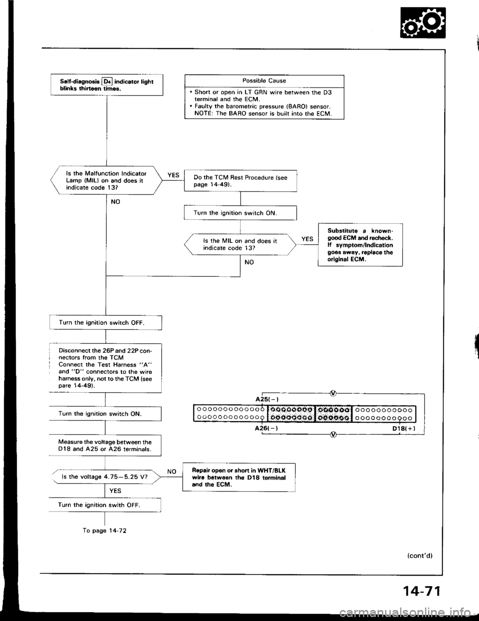
Disconnect lhe 26Pand 22P con-nectors trom the TCMConnect the Test Hahess "A"
and "D" connectors to the wireharness only, not to th€ TCM {seepare'14-49).
Possible Cause
. Short or open in LT GRN wire between the D3terminal and the ECM.. Fauky the barometric pressure {8ARO} sensor.NOTE: The BARO sensor is built into lhe ECM.
ooooooooooooo
oooooooooooo0oOOqgopg I,oiOOOOol ooo ooooooooooocqooo:Joo.oipggl o oooooo o 9ooTurn the ignition swirch ON.
Measure the voltage between theD18 and A25 or A26 terminals.
ls the voltage 4.75-5.25 V?
Turn the ignition swith OFF.
A25t- |
Soll-diagnosis Lq! indicator lightblinks thirtoon tim6.
ls rhe Malfunction lndicatorLamp (MlL) on and does itindicate code 13?
Do the TCM Rest Procedure (seepage 14-49).
Turn the ignition switch ON.
Substituto a known-good ECM and rechock.ll symptom/lndicationgoos away, .oplace theoriginal ECM.
ls the MIL on and does itindicare code 13?
Turn the ignition switch OFF.
Ropair opon or short in WHT/BLKwir6 botwoon th€ D18 to.minaland tho EcM.
fo page 14-72
14-71
Page 465 of 1413
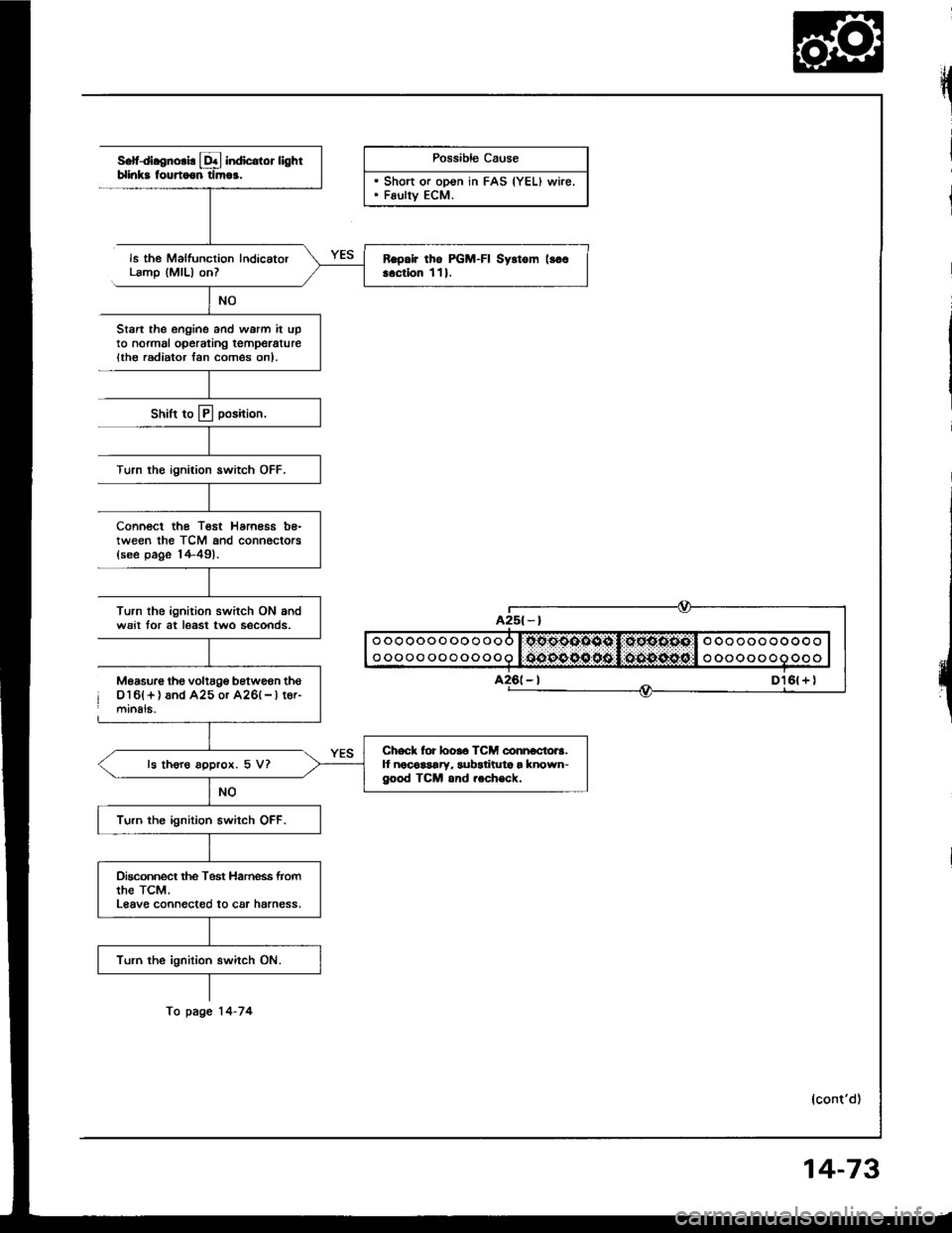
S.fdl.enorl! L&l indicdor lighlblinks fourtoon tlmoa.
ls the Malfunction IndicatorLamp (MlL) onl
Stan the ongine and warm it upto normal operating temperature{th€ radiator lan com€s on).
Shift to E position,
Turn rhe ignition switch OFF.
Possible Cause
. Sh"rt ". "e"" i" FAS |YEU ,"rirt. Fsulty ECM.
Connect the Test Harness be-tween the TCM and connociors{see page 14-491.
Turn the ignition switch ON andwsit for at least two seconds.
o oooooo ooo ooo l.tto.oodooo l:,gEoo.ottl o ooooo oooo o
o oooo oooooooo l:OOOO OO 60 l.,OO{tO.O6,'l o oooooooooo
Measure lhe voltage betwgan thso16l+ ) and A25 or A26(- | tor-mrnals.
lcont'd)
Ropair tho PGM-FI Syrtom lloo..ctlon 111.
Chock for looro TCM connoctora.lf noco$ary, subatituta a known-good TCM and .ech€ck.ls thoro approx. 5 V?
Turn the ignition switch OFF.
Dkconnect the Test Harness fromthe TcM.Leave connect€d to car harness.
Turn the ignition switch ON.
fo page 14-74
14-73