indicator HONDA INTEGRA 1994 4.G Repair Manual
[x] Cancel search | Manufacturer: HONDA, Model Year: 1994, Model line: INTEGRA, Model: HONDA INTEGRA 1994 4.GPages: 1413, PDF Size: 37.94 MB
Page 467 of 1413
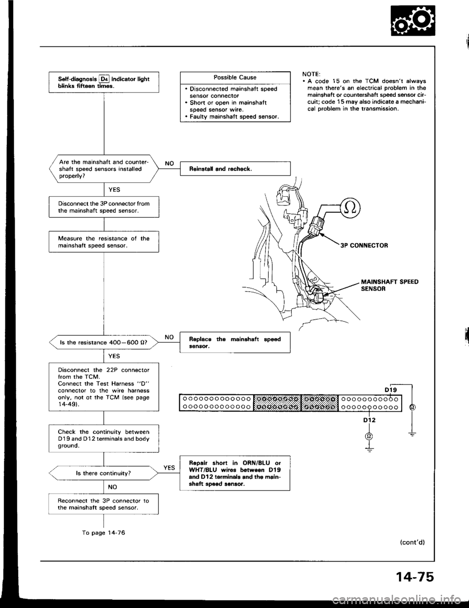
Possible Cause
. Disconnected mainshaft speedsensor connecror. Short or open in mainshaltspeed sensor wrre.. Faulty mainshatt speed sensor.
NOTE:. A code 15 on the TCM doesn't alwsysmean there's an electrical problem in themainshaft or countershaft speed sensor cir-cuit; code '15 may also indicate a mechani-cal Droblem in the transmission.
3P CONNECTOR
II o o o o o o o oo o o o o I:OtlO$O$g:Sl!:OlXOl*Ofill o o o o o o o o o O o | |
I ooooooooooooo l Sciii:ddii:ijii:l:i$idi$;d6#:l o oooop oo ooo | 6
"-f
1-L(0)Y-!
(cont'd)
solf-diagnosis E indicator lightblink tiftoon timos.
Are the mainshaft and counter-shalt speed sensors installedproperly?
Disconnect the 3P connector lromthe mainshaft speed sensor.
Measure the resistance ot themainshaft speed sensor.
ls the resistance 4OO-600 O?
Disconnect the 22P connectorfrom the TCM.Connect the Test Harness "D"
conneclor to the wire harnessonly, not ot the TCM (see page14-49).
Check the continuity betweenD19 and D12 terminals and bodyground.
Rcoair short in ORN/BLU otWHT/BLU wiros botween Dlgand Dl2 to.minals and tho main-shatt speod ronsor.
Reconnect the 3P connector tothe mainshatt speed sensor,
To page 14-76
14-75
Page 470 of 1413
Electrical Troubleshooting
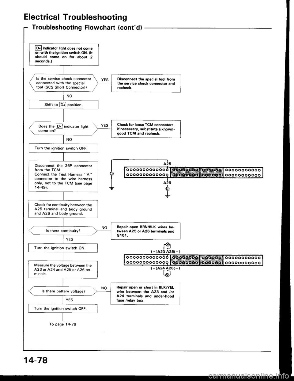
Troubleshooting Flowchaft (cont'dl
Does the @ indicatorcome on?
ls there baftery voltage?
YES
lighr
I A25
| | o ooooo o oo o ooo r:sjc.o.sl'1*st,li*os.s.4tcl ooo oo oooooo I
I I o o o o o o o o o o o o q lifrif.S..n${5git:li$gg-:aiiigitll o o o o o o o o o o o I|--.-T..-I a26
+d
+
I + )A23 A25l - l
(+ tA24 426(- |t\@
Lq4 indicator light do6s not comeon with the ignition switch ON. (ltshould come on Ior about 2seconds.l
ls the service check connectorconnected with the specialtool ISCS Short Connectod?
Diaconnect tho spocial tool fromth6 sgrvice check connoctor andrecheck.
Check {or loos6 TCM connoctors.lf necessaw, substitute a known-good TCM and recheck.
Turn the ignition switch OFF.
Disconnect the 26P connectorfrom the TCM.Connect the Test Harness "A"
conneclor to the wile harnessonly, not to the TCM (see page14-49).
Check for continuity between theA25 terminal and body groundand A26 and body ground.
R€pair open BRN/BLK wires be-twe6n A25 or A26 torminals andG 101.
Turn the ignition switch ON.
Measure the voltage between theA23 or A24 and A25 or A26 termrnals-
Repaii open or short in BLK/YELwire between tho A23 and /ot424 terminals and underhoodtuse /relav box.
Turn the ignition switch OFF.
To page 14-79
14-78
Page 540 of 1413
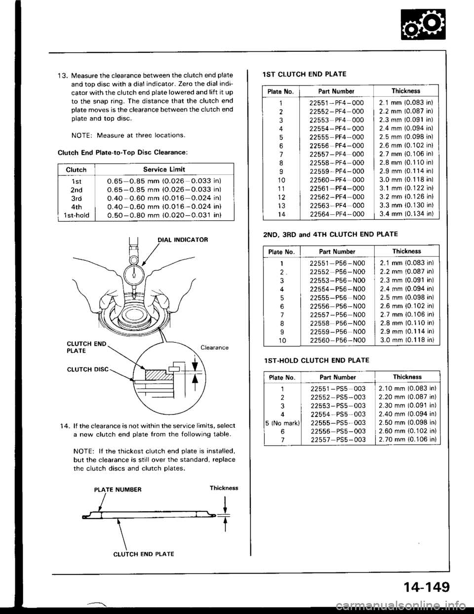
'13. Measure the clearance between the clutch end plate
and top disc with a dial indicator. Zero the dial indi-
cator with the clutch end plate lowered and lift it up
to the snap ring. The distance that the clutch end
plate moves is the clearance between the clutch end
plate and top disc.
NOTEr Measure at three locations.
Clutch End Plate-to-Too Disc Clearance:
1 4. lf the clearance is not within the service limits, select
a new clutch end plate lrom the following table.
NOTE: It the thickest clutch end plate is installed,
but the clearance is still over the standard, replace
the clutch discs and clutch Dlates.
Thickn€ss
ClulchService Limit
lst
2nd
3rd
4th
1st-hold
O.65 o.85 mm (O.026 O.O33 in)
O.65 - O.85 mm {O.026-O.O33 in)
O.4O-O.60 mm (0.O16 o.O24 in)
0.4O-0.60 mm (0.016-0.024 in)
0.50-0.8O mm {O.02O-0.031 in}
IAL INDICATOR
PLATE NUMBER
CLUTCH END PLATE
14-149
lST CLUTCH END PLATE
2ND- 3RD and 4TH CLUTCH END PLATE
lST.HOLD CLUTCH END PLATE
Plate No.Part NumberThickness
1
2
3
4
5
6
7
8
I
10
111)
IJ
14
22551-PF4-000
22552-PF4 000
22553 PF4 000
22554-PF4-OOO
22555 PF4-000
22556 PF4-000
22557 -PF4 000
22558-PF4 000
22559- PF4- 000
22560-PF4 000
22561 PF4-000
22562-PF4 000
22563-PF4 000
22564 PF4-OOO
2.1 mm 10.083 in)
2.2 mm (0.087 in)
2.3 mm (0.091 in)
2.4 mm (0.094 in)
2.5 mm (0.098 in)
2.6 mm {0.102 in}
2.7 mm i0.106 in)
2.8 mm (0.110 in)
2.9 mm (0.1 14 in)
3.0 mm (0.1 18 in)
3.1 mm (0.1 22 inl
3.2 mm {0.126 in}
3.3 mm (0.1 30 in)
3.4 mm (0.134 in)
Plate No.Part NumberThickness
1
2.
3
4
5
6
7
8
I
10
22551 P56,N00
22552-P56-N00
22553-P56-N00
22554- P56 -N00
22555-P56 N00
22556 Ps6- N00
22557 - P56 N00
22558 P56-N00
22559-P56 NOO
22560 P56-N00
2.1 mm (0.083 in)
2.2 mm (0.087 in)
2.3 mm (0.091 in)
2.4 mm (0.094 in)
2.5 mm (0.098 in)
2.6 mm {0.102 in)
2.7 mm {0.106 ini
2.8 mm (0.110 in)
2.9 mm (0.1 14 in)
3.0 mm (0.1 18 in)
Plare No.Part NumberThicknEss
1
2
3
4
5 (No mark)
6
7
22551-PS5 003
22552 PS5-003
22553-PS5 003
22554-PS5-003
22555-PS5-003
22556 PS5-003
22557 PS5-003
2.10 mm (0.083 in)
2.20 mm (0.087 in)
2.30 mm (0.09'1 in)
2.40 mm (0.094 in)
2.50 mm {0.098 in)
2.60 mm {0.102 in}
2.70 mm (0.106 in)
Page 561 of 1413
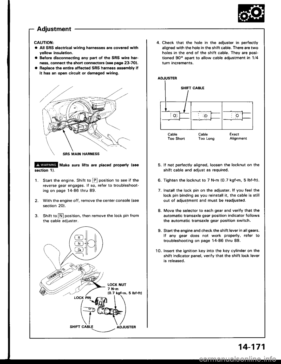
4. Check that the hole in the adiuste. in perfectly
aligned with the hole in the shift cable. There are two
holes in the end of the shitt cable, They are posi-
tioned 9Oo apart to allow cable adiustment in 1/4
lurn Incremenls.
ADJUSTER
CableI oo snonCableToo LongExactAlignment
5. It not perfectly aligned, loosen the locknut on the
shift cable and adjust as required.
6. Tighten the locknut to 7 N.m (O.7 kgf.m, 5lbf.ft).
7. Install the lock pin on the adiuster. lf you feel the
lock pin binding as you reinstall it, the cable is still
out of adjustment and must be readjusted.
8. Move the selector to each gear and verify that the
automatic transaxle gear position indicator tollows
the automatic transaxle gear position switch.
9. Start the engine and check the shift lever in all gea.s.
lf any gea. does not work properly, refer to
troubleshooting on page 14-86 thru 89.
1O. lnsert the ignition key into the key cylinder on the
shift indicator panel, ve.ify that the shift lock lever
is released,
CAUTION:
a All SRS electrical widng harn€sses are covar€d with
yollow insulation.
a Before disconnecting any part of ths SRS wire har-
ness, connect the shon connectors (see page 23-701.
a R€place the entire affected SRS halnass asssmbly it
it has an op€n circuit or damaged wiring.
@ tu"t" sure lifts a.e placed properly ls66
ssction 1).
Start the engine. Stritt to @ position to see if the
reverse gear engages. lf so, refer to troubleshoot-
ing on page 14-86 thru 89.
Wilh the engine off, remove the center console {see
section 20).
Shilt to N position. then remove the lock pin from
the cable adjuster.
'1.
/
''fidlfr
I
t+@
\/ \
CABLE-.'.-_--l../ADJUSTER
]H
@
@
@
Adjustment
14-171
Page 563 of 1413
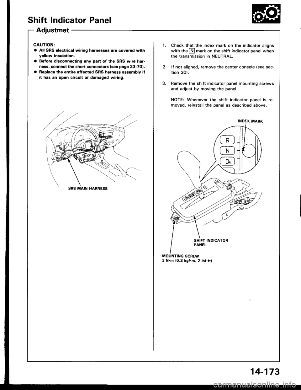
Shift Indicator Panel
Adjustmet
CAUTION:
a All SRS olectrical wifng harnesses aro covered withyellow insulation.
a Bofors disconnecting any pan of the SRS wire har-
ness, connect tho sho.t connectors {sse page 23-7O),
a Replace the entire aflect€d SRS harness assembly if
it has an open circuit or damaged wiring,
1.Check that the index mark on the indicator aligns
with the N]mark on the shift indicator panel when
the transmission in NEUTRAL.
lf not aligned, remove the center console (see sec-
tion 2O).
Remove the shift indicator panel mountinq screws
and adjust by moving the panel.
NOTE: Whenever the shift indicator panel is re-
moved, reinstall the panel as described above.
MOUNTING SCREW3 N'm lO.3 kst.m, 2 lbf.ftt
INDEX MARK
@
@
@
SRS MAIN HARNESS
14-173
Page 634 of 1413
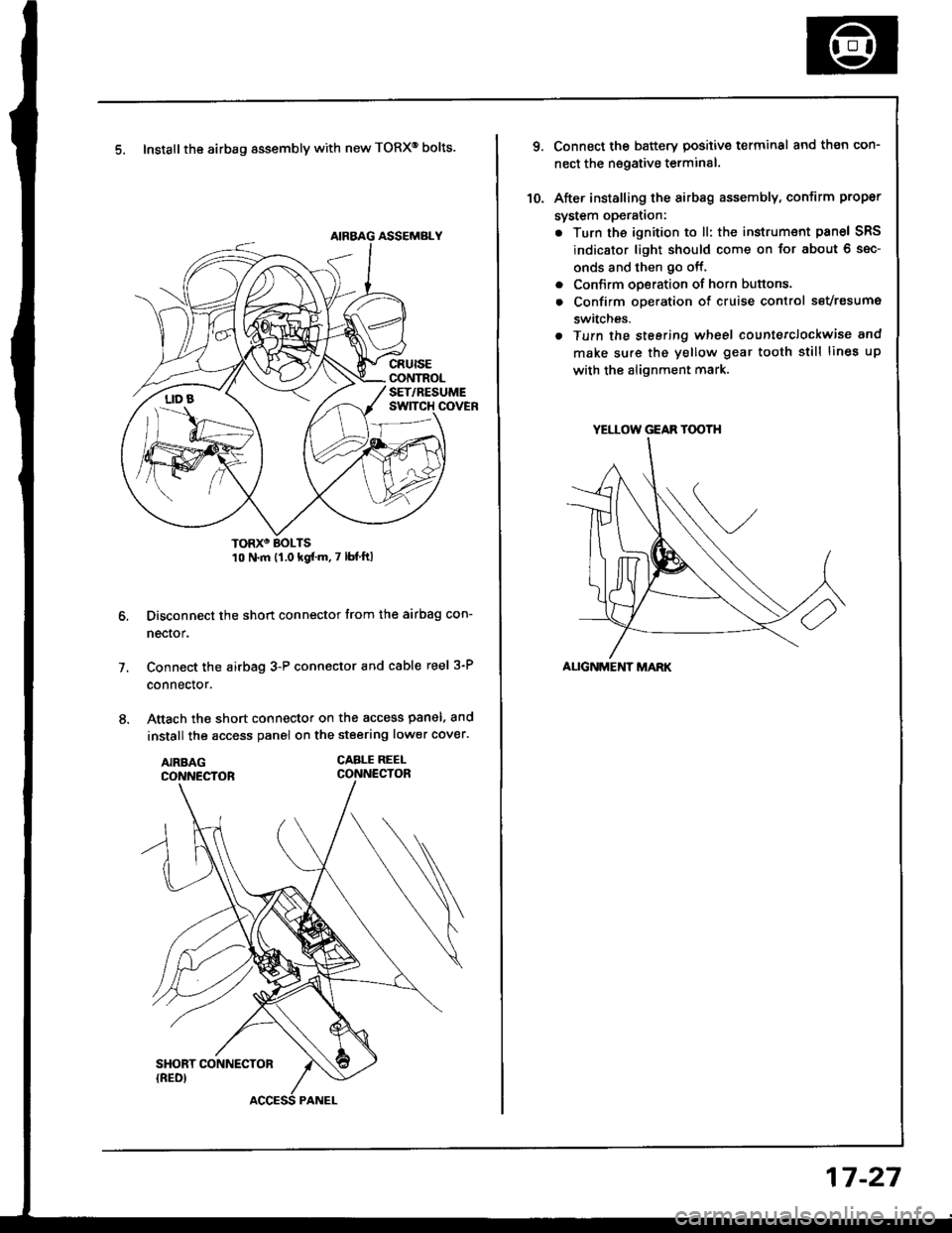
5. Install the airbag assembly with new TORXo bolts.
TORXO BOLTS10 N.m {1.0 kgf'm.7 lbf ftl
Disconnect the short connector trom the airbag con-
nector.
Connect the airbag 3-P connector and cable reel 3-P
connector.
Attach the short connector on the access panel. and
install the access panel on the steering lower cover.
CABLE REEI-CONNECTOR
7.
YELLOW GEAR TOOTH
ALIGNMENT MARK
10.
Connect the battery positive terminal and th€n con-
nect the nsgative terminal.
After installing the sirbag assembly, confirm proper
system opera(on:
. Turn the ignition to ll: the instrum€nt pan6l SRS
indicator light should come on for about 6 sec-
onds and then go off,
. Confirm operation of horn buttons.
. Confirm oDeration of cruise control sevresume
switches.
a Turn the steering wheel countetclockwise and
make su.e the yellow gear tooth still lines up
with the alignment mark.
17-27
Page 670 of 1413
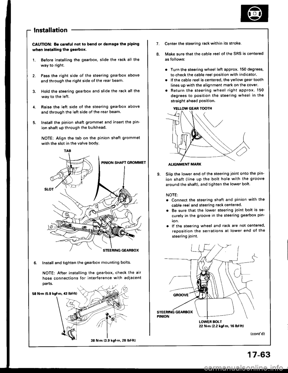
lnstallation
CAUTION; BG Glrc{ul not io bcnd or drm8go tho piping
whcn in3tllling tho gea.box.
1. Before installing the gearbox, slide the rack all the
way to right.
2. Pass the right side of the steering gearbox above
and through the right side of the rear beam.
3. Hold the steering gearbox and slide the rack all the
wav to the left.
4. Raise the left side of the steering gearbox above
and through the left side of the rear beam.
5. Install the pinion shaft grommet and insert the pin-
ion shaft up through the bulkhead.
NOTE: Align the tab on the pinion shaft grommet
with the slot in the valve bodv.
6. Install and tighten the gearbox mounting bolts.
NOTE: After installing the gearbox, check the air
hose connactions for interference with adjacent
pans.
58 N.m 15.9 kg[.m, $ lbl.ftl
TAA
38 N m 13.9 kgl.m, 28 lbt.ftl
17-63
YELLOW GEAR TOOTH
7.Center the steering rack within its stroke.
Make sure that the cable reel of the SRS is centered
as follows:
. Turn the steering wheel left approx. 150 degrees,
to check the cable reel position with indicator.
. lfthe cable reel is centered. the yellow gear tooth
lines up with the alignment mark on the cover.
. Return the steering wheel right approx. 150
degrees to position the steering wheel in the
straight ahead position.
ALIGNMEi'IT MARK
Slip the lower end of the steering joint onto the pin-
ion shaft (line up the bolt hole with the groove
around the shaft), and tighten the lower bolt.
NOTE:
. Connect the steering shaft and pinion with the
cable reel and steering rack centered.
. Be sure that the lower steering ioint bolt is se-
curely in the groove in the steering gearbox pin-
ion.
. lf the steering wheel and rack are not centeted,
reposition the serralions at lower end of the
steering joint.
(cont'dl
22 N.m 12.2 kgi.m, 16lbf.ftlLOWER BOLT
Page 998 of 1413
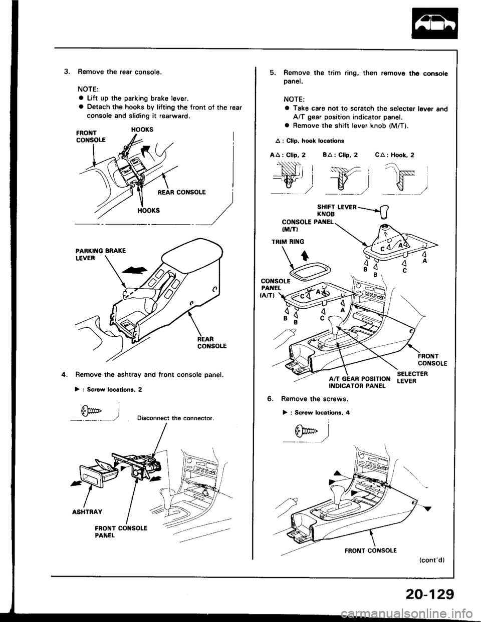
3.Remove the rear console,
NOTE:
a Lift up the parking brake lever.
a Oetach the hooks by lifting the front ot the rear
console and sliding it rearward.
Remove the sshtrsy and front console panel.
> : Scrow locatlon3, 2
Diaconn€ct the connector.
4.
l
5. Remove the trim ring, then remov€ th€ consolepanel.
NOTE:
a Take cafe not to scratch the selecter l6ver 8ndA/T gear position indicator panel.
a Remove the shiJt lever knob (M/T).
A : Cllp, hook loc.tions
AA : Clip, 2 BA : Cllp, 2 CA : Hook, 2
SHIFT I.EVERKNOB
CONSOLE PANEL
IM/TI
TRIM RI'{G
"onroar€
,"Hr"t z{o$
co soLE
POStTtONSELECTERLEVEBINDICATOR PANEL
6. Remove the screws.
> : Screw locationr, 4
6bo'' I:./
20-129
Page 999 of 1413
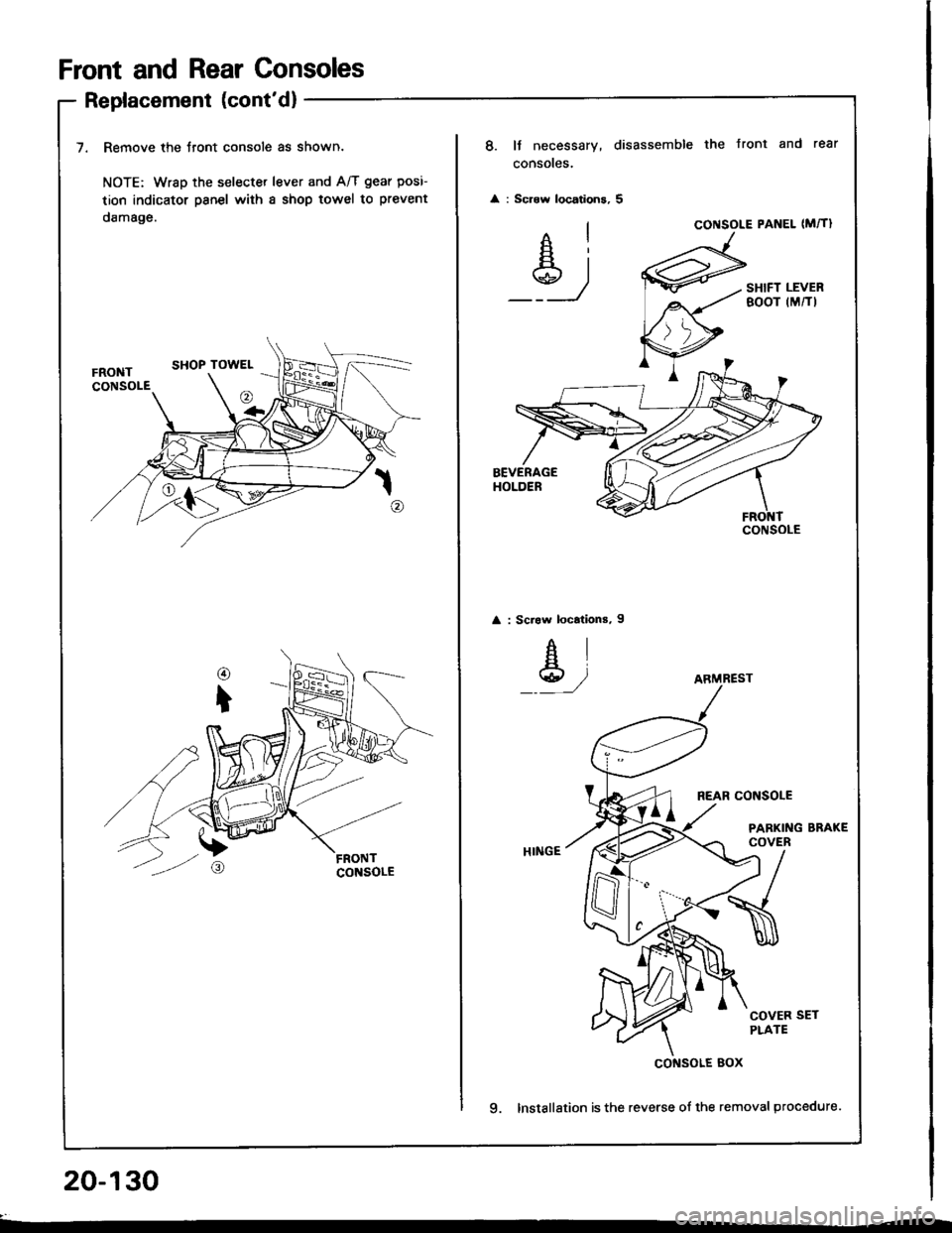
Front and Rear Consoles
Replacement (cont'd)
7. Remove the Jront console as shown.
NOTE: Wrsp the selecter lever and A/T gear posi-
tion indicator psnel with a shop towel to prevent
damage.
20-130
8. It necessary, disassemble the Jront and rear
consoles.
: Scrow locations, 5
Ai
_Y_)
CONSOLE PANEL (M�TI
SHIFT LEVERBOOT (M/TI
: Scraw locations, I
AI
Y,/
REAR CONSOLE
PARKING BRAKECOVER
COVER SETPLATE
9. Installation is the reverse of the removal procedure.
CONSOLE
ARMREST
cof{solE Box
Page 1007 of 1413
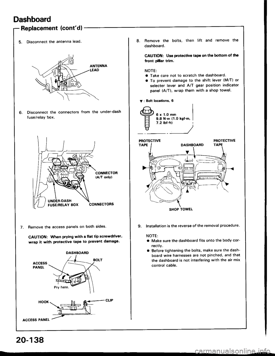
Dashboard
Replacement (cont'd)
5. Disconnect the antenna lead.
Disconnect the connectors
fuse/relay box.
from the under-dash
CONNECTOR(A/T only)
CONNECTORS
Remove the access panels on both sides.
GAUTION: When prying with 8 tlat tip scrowdrivor'
wrap it with protective tapo to pl€vent damaga'
accEssPANEL
6.
DASHBOARD
HooK ___E-- RE=-cLrP
ffiL
lcCesS Plnel /
20-138
8.Remove the bolts, then lift and remove the
dashboard.
CAUTION: Use protoctive tspe on the bottom ol tha
lront tillar trim;
NOTE:
a Take care not to scratch the dashboard.
a To prevent damage to the shift lever (M/T) or
selecter lever and A/T gear position indicator
panel (A/T), wrap them with a shop towel.
V : Bolt locations, 6
6 x 1.0 mm9.8 N.m (1.0 kgt'm, I7.2 tbt.ftt
____/
PROTECTIVE
9. lnstallation is the reverse of the removal procedure
NOTE:
a Make sure the dashboard fits onto the body cor-
rectly.
a Before tightening the bolts, make sure the dash-
board wire harnesses are not pinched, and thal
the dashboard is not interfering with the air mix
control cable.
SHOP TOWEL