cks HONDA INTEGRA 1994 4.G Repair Manual
[x] Cancel search | Manufacturer: HONDA, Model Year: 1994, Model line: INTEGRA, Model: HONDA INTEGRA 1994 4.GPages: 1413, PDF Size: 37.94 MB
Page 1102 of 1413
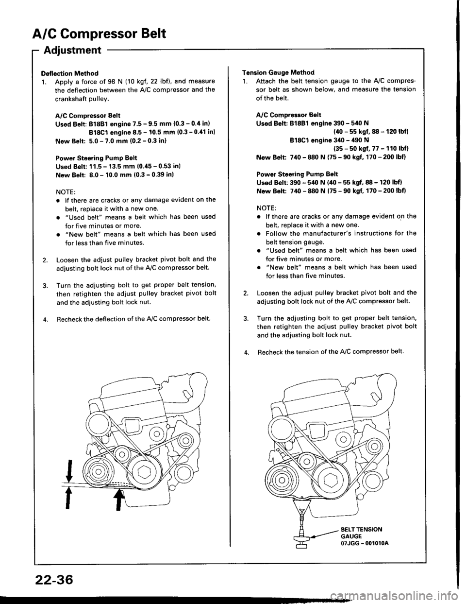
A/C Compressor Belt
Adjustment
Dstlsqtion Method
1. Apply a force of 98 N (10 kgf, 22 lbf), and measure
the deflection between the A,/C compressor and the
crankshaft Dullev.
A/C Compressor Belt
Us€d Eelt: 81881 engine 7.5 - 9.5 mm (0.3 - 0.4 in)
Bl8Cl engine 8.5 - 10.5 mm (0.3 -0.11 inl
New Belt: 5.0 - 7.0 mm (0.2 - 0.3 inl
Power Stesring Pump Belt
Used Beli: 'l1.5 - 13.5 mm (0.,[5 - 0.53 inl
New 8€lt: 8.0 - 10.0 mm (0 3 - 0.39 inl
NOTE:
. lf there are cracks or any damage evident on the
belt, replace it with a new one.
. "Used belt" means a belt which has been used
for five minutes or more.
. "New belt" means a belt which has been used
for less than five minutes.
2. Loosen the adjust pulley bracket pivot bolt and the
adjusting bolt lock nut of the Ay'C compressor belt.
3. Turn the adiusting bolt to get proper belt tension,
then retighten the adjust pulley bracket pivot bolt
and the adjusting bolt lock nut.
4. Recheck the deflection of the lvc compressor belt
22-36
Tonsion Gauge Method
1. Attach the belt tension gauge to the Ay'C compres-
sor belt as shown below, and measure the tension
of the belt.
A/C Compressot Belt
Used 8€lt: Bl8Bl engine 390 - 540 N
(40 - s5 kgf, 88 - 120 lbfl
Bl8Cl ongine 3il0 - il90 N
(35 - s0 kgf, 77 - 110 lbfl
N€w Belt 7,10 - 880 N {75 - 90 kgf, 170-200lbl}
Powor Steoring Pump Belt
Used Belt: 390 - 5,{l N (40 - 55 kgf, 88 - 120 lbll
N6w Bolt: 74O - 880 N 175 - 90 kgf, 170-200lbt)
NOTE:
. lf there are cracks or any damage evident on the
belt, replace it with a new one.
. Follow the manufacturer's instructions for the
belt tension gauge.
. "Used belt" means a belt which has been used
for five minutes or more.
. "New belt" means a belt which has been used
tor less than five minutes,
2. Loosen the adjust pulley bracket pivot bolt and the
adjusting bolt lock nut of the AVC compressor belt.
3, Turn the adjusting bolt to get proper belt tension,
then retighten the adjust pulley bracket pivot bolt
and the adjusting bolt lock nut.
4. Recheck the tension of the A{/C compressor belt.
Page 1107 of 1413

Electrical
Special Tools
Troubleshooting
Tips and Precautions ................................ 23-3Five-stop Tloubleshooting ..............,...-..-... Z3-sSchematic Symbols ................................_. 23-6wire Color Cod€s ..................................... 23-6Relay and Control Unit Locations
Engine Compartment .........,............ ... --. 23-7Dsshboard and Door ..,,......................... 23-gDashboard and Floor ............................. 23-t OOuaner Panel .....-.....23-12Connector ldentification and WireHarness Routing ........ 23-i 3
Index to Circuits and Systems
Airbag ............... ...-..-... 2g-26sAir Conditioning ....,.. Section 2lAltelnator ......_.............. 23-99Anti-lock Brake Systsm (ABS) Section 19Automatic Transmission Section 14Battery .............. .......... 23-66Chafging System ........... 23-98rCigalstte Lighter .....................-...-......-..-.. Z3-2O4Cfock ................. ..........23-197rcruise Controf .......--..-... 23-242Distributor .................... 23-87Fan Controls ................. 23-1ogFuel and Emissions ... Section 1i*Fuses
Under-dash Fuse/Relay Box ................... 23-48Undor-hood ABS Fuse/Retay Box ............ 23-51Under-hood Fuse/Relay Box,.................. 23-52rGauges
Engine Coolant Temperature {ECT)Gauge ................ ..23-126Fuef cauge ............... 2g-123'Gauge Assembly ....--.23-113Speedometer .....-...,,. 23-114Tachometer .....,.....-.. 23-114Ground Distribution ........ 23-60Heater ,,,........,.... ..... Section 2lrHorn ................. ........... 23-199*fgnition Switch ............. 23-70fgnition Syst6m .......-..-.. 23-A7lgnition Timing .............. 23-89Indicator Lights"A/T Gear Position .............. ................... 23-1 32B1ak6 System ...,..,..-.23-127Engine Oil Pressura .............................. _ 23-1 51Low Fuel ............ ......23-125Malfunction Indicator Lamp {MlL} ...,,. Section I l
tfnteglated Control Unit ...29-144*lnterlock System ...................................... 23-1 3gLights, Exteriol
Back-up Lights ........... 23-179Brake Lights .............. 23-t8ltDaytime Running Lights {Csnada} ........... 23-156Front Palking Lights ............................. 23-1 65Flont Side Marker Lights ....................... 23-165Front Turn Signal Lights ........................ 23-1 65*Hazard Warning Lights .........................- 2g-1A4Headlights ................. 23-t6tLicense Plate Lights .............................. 23-1 69Taillights(Harchback) .......... 23-166
{Sedan) .............. .. 23-167Lights. Inteliol
Cargo Area Light {Hatchback) ...... -.. -.. -... 23-177Ceifing Light ........-..-.23-175
Dash Lights Blightness Controt .............. 23-t70Glove Box Lighr ................................... 23-1 69Spotfighr ............ ....-.23-174Trunk Light (Sedanl ............... .............. - 23.-177*Lighting Sysrem .......-.-... 23-152:Moonroof ,,.,.......,..,,,,,.-.23-211PGM-FI Systom ........ S€crion 11Power Distribution .,.-..--..23-54Power Door Locks .............,,..................... 23-233Power Mirors ..,..,....-...- 23-216Power Relays ...........,..... 23-68Power Windows ............ 29-222*Rear Window Defogger ........,... ..........,..... - 23-20,6Reminder Systems
Key-in Remindel System ....,.............,.... 23-1 50Lights-on Reminder System ................... 23-l 5f*Maintenance Reminder system ..,,.... -.. - -. 23-.1 2gSeat Belt Reminder System ..................- 23-125*Side Markel/Turn Signal/Hazard
Ffasher System .,..,..-.23.-1A4Spark Pfugs .........-...-..... 23-97Starting System ....,,.....-. 23-73*Stereo Sound System ...,.......................,,.. 23-l gg
Supplemental Restraint System {SRS} ......... 23-265Vehicfe Speed Sensor {VSS) .............--..-.... 23-122*Wiper/Washer Systom ...............--.........-..- Zg-254
rRead SRS pi€cautions on Page 23-271 betore workingin these areas.
-+
Page 1109 of 1413
Troubleshooting
Tips and Precautions
Before Troubloshooting
a Check applicable fuses in the appropriate fuse/relay
DOX.
a Check the battery for damage, state of charge, and
clean and tight connections.a Check the alternator belt tension.
CAUTION:
a Do not quick-charg€ a battery unless the batteryground cabla has be€n disconnoctsd. oth€rwisoyou will damage the alternator diodss.a Do not att6mpt to crank the engine with the bat-tery ground cable loosely connectsd or you will se-vorsly damag€ tho widng.
a The original radio has a codod thatt plotection ci.-cuit. Be sul€ to got tho customor's code numbet
before- disconnecting th€ battery.- lomoving tho No. 32 (7.5 Al tuso f.om the
under-hood tuse/lelay box.- removing tho radio.
Aflor s€lvic€. reconn€ct powet to tho radio and
turn it on. Whon the word "CODE" is displayed,
€nt€l the customer'E s-digit codo to .astore ladio
operation.
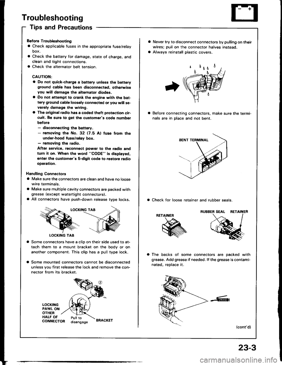
Handling Connectors
a Make sure the connectors are clean and have no loose
wire terminals.
a Make sure multiple cavity connectots are packed withgrease (except watertight connectors).a All connectors have push-down release type locks.
LOCKII{G TAA
LOCKING TAB
a Some connectors have a clio on their side used to at-
tach them to a mount bracket on the body or on
another component. This clip has a pull type lock.
a Some mounted connectors cannot be disconnected
unless you first release the lock and remove the con-
nector from its bracket.
LOCKINGPAWL ONOTHERHALF OFPull toorsengageCONNECTORBRACKET
23-3
a Never try to disconnect connectors by pulling on thei.
wires; pull on the connector halves instead.
a Always reinstall plastic covers.
Belore connecting connectors, make sure the lermi-
nals are in Dlace and not bent.
a Check tor loose retainer and rubber seals.
RETAINER
a The backs of some connectors are oacked with
grease. Add grease if needed. It the grease is contami-
nated, reDlace it.
(cont'd)
Page 1110 of 1413
Troubleshooting
Tips and Precautions (cont'dl
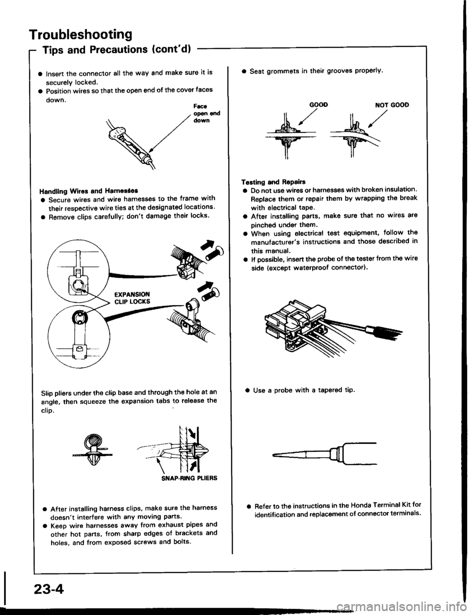
a lnsert the connector all the way and make sure it is
securely locked.
a Position wires so that the open end of the cover taces
down.Facaopon andcown
V
Handling Wir€s and Hamorao8
a Secure wires and wile harnesses to the frame with
their respective wire ties at the designated locations'
a Remove clips carefully; don't damage their locks'
Stip pliers under the clip base and through the hole at an
angle, then squeeze the expansion tabs to release the
clio.
SI'IAP-ANG PLIERS
a After installing harness clips, make su.€ the hatness
doesn't interfe.e with any moving parts.
a Keeo wire hatnesses away from exhaust pipes and
other hot parts, ftom sharp edges of brackets and
holes, and from exposed screws and bolts.
23-4
GOOD ]TOT GOOD
n,/r/ll ,,' ll ,,
s*j -:ut*/-.w-- --ry\
il,,
Tosting and Ropails
a Do not us€ wires or harness€s with broken insulation.
Replace them or repair them by wrapping th€ break
with electrical tape.
a After installing pans, make sure that no wir€s are
Dinched undsr them.
a When using electrical test €quipment, follow the
manufacturer's instructiona and those dsscribed in
this manual,
a It possible, insert the probe of the toster from the wire
side {except waterproof connector).
a Seat grommets in theil grooves properly.
a Use a probe with a tapered tip.
Refer to the instructions in the Honda Terminsl Kit for
identification and .eplacement o{ connector telminals'
Page 1156 of 1413
![HONDA INTEGRA 1994 4.G Repair Manual Fuses
Under-dash Fuse/Relay Box (contd)
NOTE: View from the backside of the under-dash tuse/relay box
c916[To m.in wlro h.rnr.t lol39]l
cgt5tTo ..r wftt hJtr.r (CsOrDl
c9r4[To Int grrtad control unhl HONDA INTEGRA 1994 4.G Repair Manual Fuses
Under-dash Fuse/Relay Box (contd)
NOTE: View from the backside of the under-dash tuse/relay box
c916[To m.in wlro h.rnr.t lol39]l
cgt5tTo ..r wftt hJtr.r (CsOrDl
c9r4[To Int grrtad control unhl](/img/13/6067/w960_6067-1155.png)
Fuses
Under-dash Fuse/Relay Box (cont'd)
NOTE: View from the backside of the under-dash tuse/relay box
c916[To m.in wlro h.rnr.t lol39]l
cgt5tTo ..r wftt hJtr.r (CsOrDl
c9r4[To Int grrtad control unhlc917[To mrin wh.
c913c91
lTo m.in wlro hlni.rr (qt38)ltTo r..r w|? hrt|.|t (C6O3ll
23-50
Page 1159 of 1413
![HONDA INTEGRA 1994 4.G Repair Manual NOTE; View from the backside of the under-hood fuse/relav box
c907lTo m.ln wiro h.mo$ (C214)l
[To msin wlro hEmoss lc215l]
c911lTo ftain wiro hamers (C218)l: USA
lTo mlln wlr. hlmct. (C216li
lTo mrin HONDA INTEGRA 1994 4.G Repair Manual NOTE; View from the backside of the under-hood fuse/relav box
c907lTo m.ln wiro h.mo$ (C214)l
[To msin wlro hEmoss lc215l]
c911lTo ftain wiro hamers (C218)l: USA
lTo mlln wlr. hlmct. (C216li
lTo mrin](/img/13/6067/w960_6067-1158.png)
NOTE; View from the backside of the under-hood fuse/relav box
c907lTo m.ln wiro h.mo$ (C214)l
[To msin wlro hEmoss lc215l]
c911lTo ftain wiro hamers (C218)l: USA
lTo mlln wlr. hlmct. (C216li
lTo mrin wiro hameq lC217ll
23-53
Page 1162 of 1413
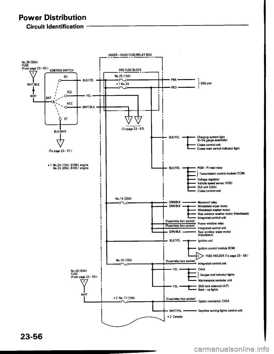
Power Distribution
Circuit ldentification
IGNITION SWITCH
+page 23-
r 1 No.24115A): 81881 engin€No.24 l20A): Bl8C1 6ngin.
N0.40 {504)FUSE(From pago 23 - 551
UNDER - DASH FUSE/REIAY BOX
sRs FusE 81-0cK
No.25l10Al
No.14l20A)
No.l5 {1041
Chuging sY3l.m lightlln tho g6ug€ s3€mblyl
Cruis€ controlunitCdis6 msin 3whch itdicttor light
PGM - Fl mlin r6lry
) lrrmmirdon control modulo [ICM)
Vohag6 rcoulatorVehiclo sp.€d somor IVSS)E|.l) unit IUSA)Crube conttol unit
Moonrcof rclayWind.hicld wipot motorWirdlhi€ld waah6. motorR6ar window ws3hor motot {HrtchblctlInt.gGtod control unit
Power wirdow tclaY
Int6lrat€d contrcl unit- R6af window wipor motol(H3tchbtck)
571
GRNiEI(GRNAt(
GRN/8I..K
BLKffEt
-EiT"h#,H#J:r"
Shitt lock solenoU {MlEack -up lights
option conn€ctor: C924
Daytimo running lights conttol unit
YEt..--
lrcz
Ml t -'-
\'- _ ^ACC
23-56
*2 No.17 {1041bor sockstl
Page 1164 of 1413
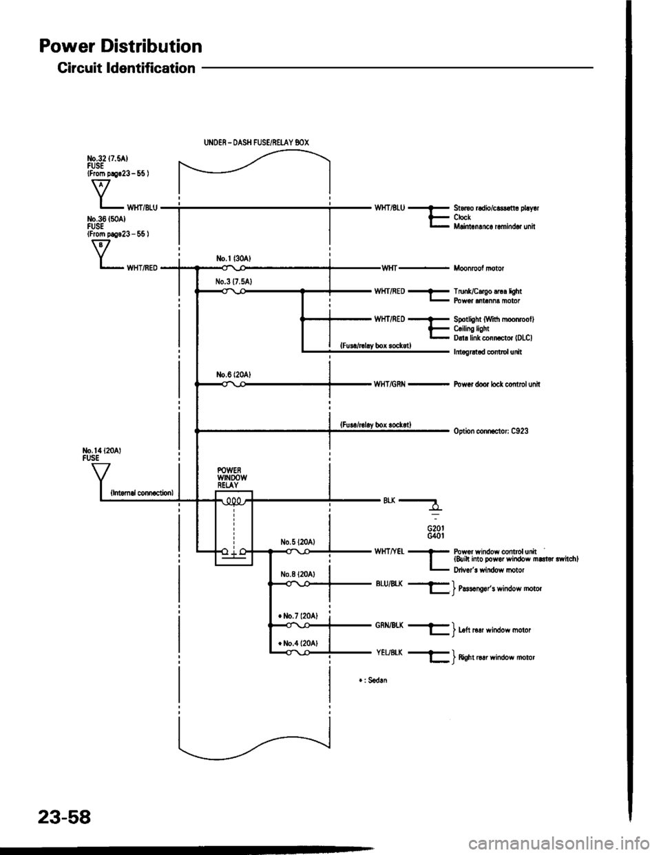
Power Distribution
Circuit ldentification
No,14l20 lFUSE
{lntomal connaclionl
UNOER - OASH FUSE/REI-AY BOX
WHT/RED - TrunUcergo .rur lght- Fbwer .nr.nn! moror
WHT/REof
Ebox sockstl
WHT/GRN -
*-
G20tG40l
Spotlight (Wrt'h moonmollC.ilin! lightDrl! link conn ctor lDLCl
Irtogrltad control unit
Pow6r door locl control unit
option connoclor: C923
WHTIYEL * Powor window conttolunrt| {&ih into Dowor window marloi rwhchll- p,i""1" *;n6o* n o1o,
BLU/4X +ll_ | l,lssrng6r's wndow motor
GRN/BLX -
YEUE|-K -
) Left rerr window moror
) ftenr oar winoow motor
r: Sedln
23-58
Page 1176 of 1413
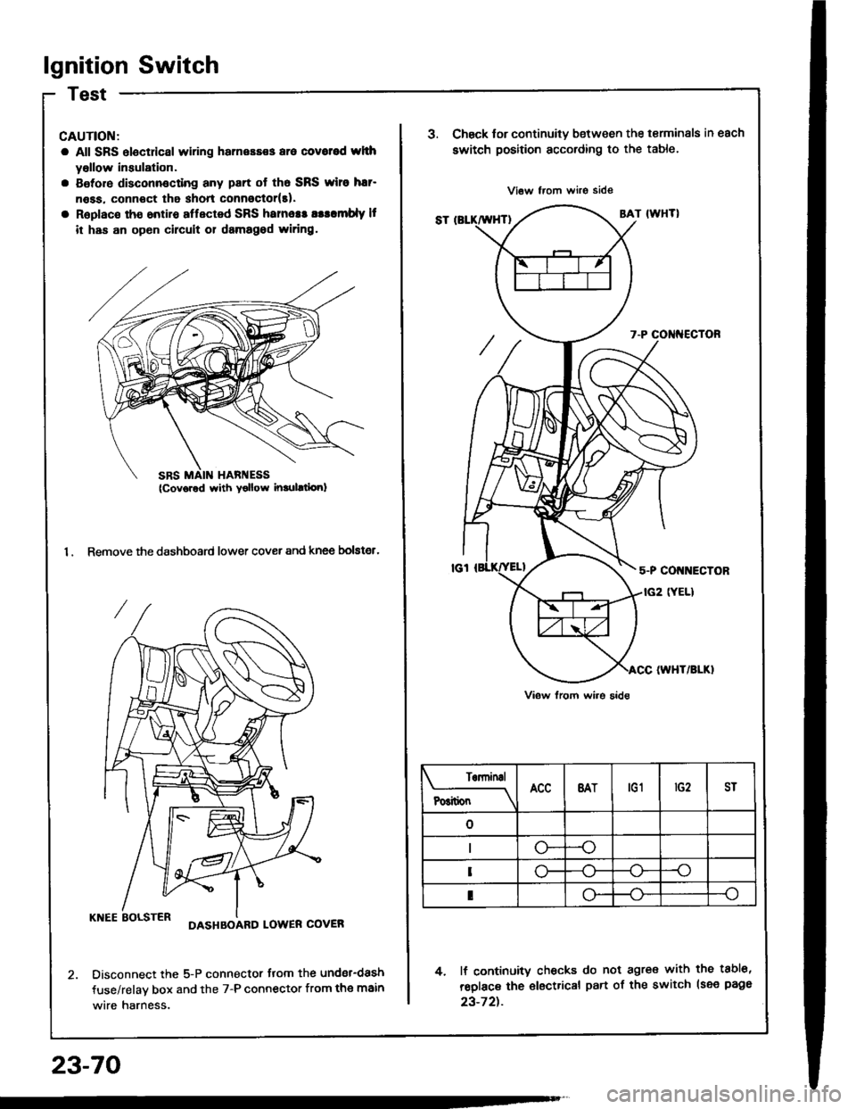
lgnition Switch
CAUTION:
a All SRS electdcal wiring harnessss aro covotod whh
yollow insulation.
a Botore disconnocting any part ot th6 SRS wiro har-
n6ss. connoct tha shon connoctor(t).
a Replac€ tho ontiro affected SRS hames! asllmbly It
it has an op6n circuit 01 damagod widng.
1. Remove the dashboard lower cover and knee bolster.
KNEE BOLSTERDASHBOARD LOWER COVER
Disconnect the 5-P connector flom the undsr-dash
fuse/relav box and the 7-P connector from the main
wire harness.
23-70
SRS MAIN HARI{ESS(Cov6red with Yollow inrulltiori)
J.Chsck tor continuity b€tween the terminals in each
switch position according to the table.
4. lf continuity checks do not agre€ with the tabl6,
reolace the €lectrical part of the switch lsee page
23-72t.
Terninal
P6itionBATtG1ST
--o
o-
I
Page 1189 of 1413
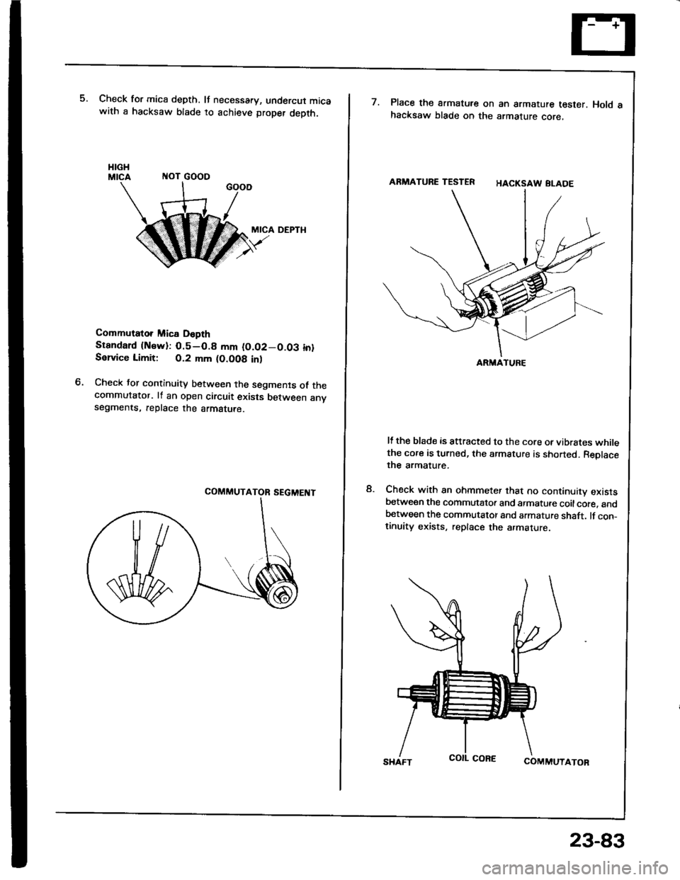
Check for mica depth. It necessary, undercut micawith a hacksaw blade to achieve proper depth.
ITOT GOOO
MICA DEPTH
Commutator Mica D6pth
Stsndard {Nsw):0.5-0.8 mm (O.O2-0.03 in}Sslvice Limit: 0.2 mm (O.OO8 inl
Check tor continuity between the segments of thecommutator. lf an open circuit exists between anvsegments, replace the armatute.
M
ARMATURE TESTER
ARMATUFE
Place the armatute on an armature tester. Hold ahacksaw blade on the armature core,
HACKSAW BLADE
It the blade is attracted to the core or vibrstes whilethe core is turned, the armature is shorted. Reolacethe armature.
Check with an ohmmeter that no continuity existsbetween the commutator and armatute coilcore. andbetween the commutator and armature shaft. lf con_tinuity exists, replace the armature
COMMUTATOR
8.
SHAFT
23-83