Detent spring HONDA INTEGRA 1994 4.G Workshop Manual
[x] Cancel search | Manufacturer: HONDA, Model Year: 1994, Model line: INTEGRA, Model: HONDA INTEGRA 1994 4.GPages: 1413, PDF Size: 37.94 MB
Page 500 of 1413
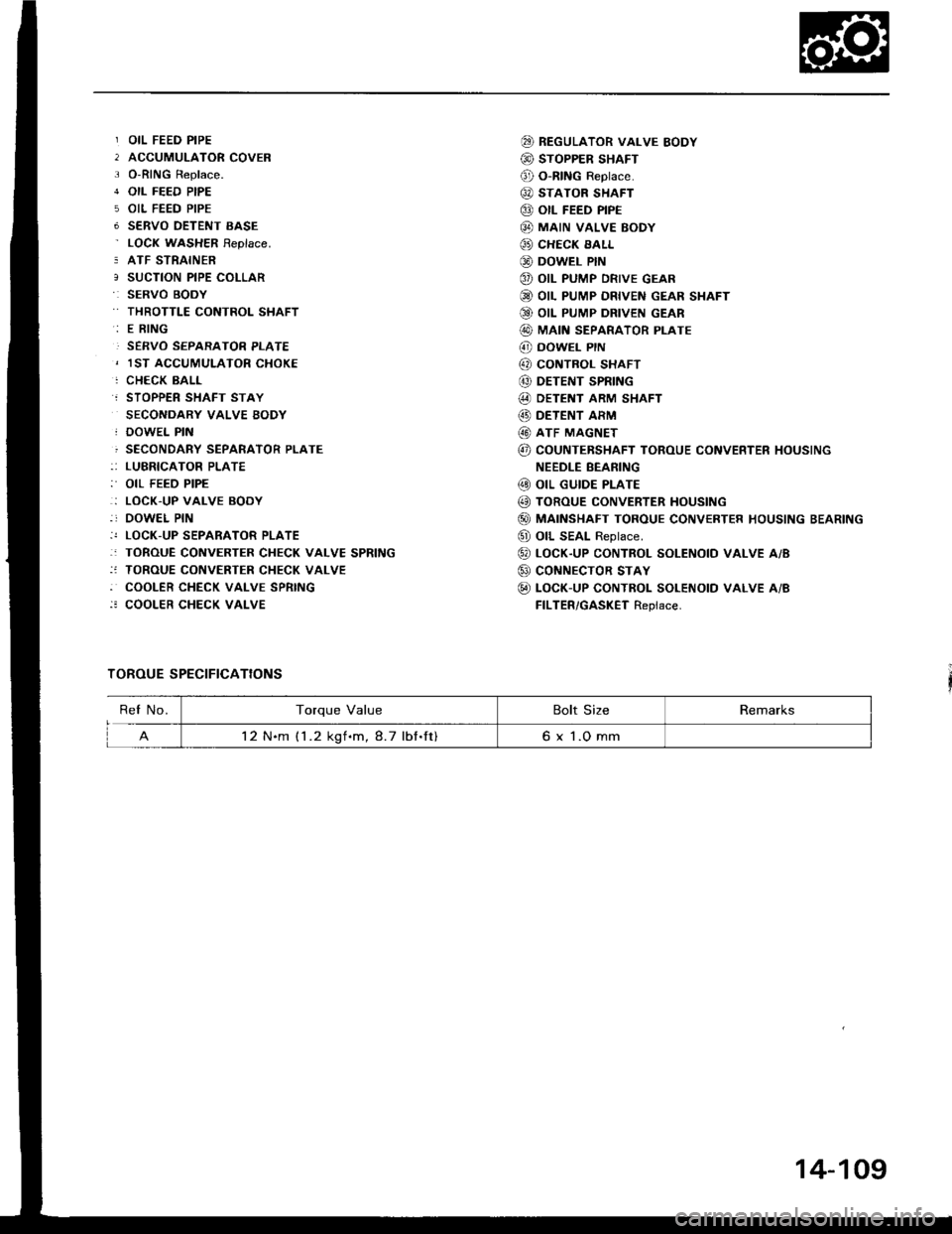
OIL FEED PIPE
ACCUMULATOR COVER
O-RING Replace.
OIL FEED PIPE
OIL FEED PIPE
SERVO OETENT EASE
LOCN WASHER Feplace.
ATF STRAINER
SUCTION PIPE COLLAR
SERVO BOOY
THROTTLE CONTROL SHAFT
E RING
SERVO SEPARATOR PLATE
1ST ACCUMULATOR CHOKE
CHECK BALL
STOPPER SHAFT STAY
SECONDARY VALVE BODY
DOWEL PIN
SECONDARY SEPARATOR PLATE
LUBRICATOR PLATE
OIL FEED PIPE
LOCK.UP VALVE BODY
DOWEL PIN
LOCK-UP SEPARATOR PLATE
TOROUE CONVERTER CHECK VALVE SPRING
TOROUE CONVERTER CHECK VALVE
COOLER CHECK VALVE SPRING
COOLER CHECK VALVE
TOROUE SPECIFICATIONS
@ REGULAToR vALvE BoDY
@ STOPPER SHAFT
@ O-RING Reptace.
@ STATOR SHAFT
@ otl FEED PIPE
@ MAIN vALvE BoDY
@ CHECK EALL
@ DowEL PIN
@ oIL PUMP DRIVE GEAR
@ OIL PUMP DRIVEN GEAR SHAFT
Q9 OIL PUMP DRIVEN GEAR
@ MAIN SEPARAToR PLATE
@ DowEL PrN
@ coNTBoL sHAFT
@ DETENT SPRING
@ DETENT ARM SHAFT
@) DETENT ARM
@ ATF MAGNET
@ COUNTEBSHAFT TOROUE CONVERTER HOUSING
NEEDLE BEANING
@ oIL GUIDE PLATE
@ TOROUE CONVERTER HoUSING
@) MAINSHAFT TOROUE CONVERTER HOUSING BEARING
@ oll SEAL Reptace.
@ LocK-up coNTRoL soLENotD vALvE A/B
@ coNNECTOR STAY
@ LOCK-UP CONTROL SOLENOTD VALVE A/B
FILTER/GASKET Replace.
ReI No.Torque ValueBolt SizeRemarks
12 N.m (1 .2 kgf.m, 8.7 lbf.ft)6 x 1.O mm
14-109
Page 506 of 1413
NOTE:
a Clean all parts thoroughly in solvent or carbuetor
cleaner and dry with compressed air.a Blow out all passages.
a When removing the valve body replace the following:. O-rings. Lock wsshers
1 . Remove the oil feed pipes from the servo body, s€r-
vo detent base, accumulatof cover, lock-uD valve
body and main valve body.
2, Remove the three bolts securing the ATF strainer and
servo detent base, then remove them.
3. Remove the three bolts securing the accumulator
cover. then remove the accumulator cover.
4. Remove the six bolts secu.ing the servo body, then
remove the servo body and separator plate.
5. Remove the bolt securing the secondary valve body,
then remove the secondary valve body and separa-
tor plate.
6. Remove the eight bolts securing the lubricator plate
and lock-up valve body, then remove the lubricatorplate, lock-up valve body and separator plate.
7. Femove the bolt securing the.egulator valve body,
then.emove the regulator valve body.
8. Remove the stator shaft and stopper shaft.
9. Remove the detent spring t,om the detent arm. thenremove the control shaft from the torque convenerhousing.
1O. Remove the detent arm and detent afm shaft t.om
the main valve bodv.
1 1 . Remove the four bolts secu.ing the main valve body,then remove the main valve body.
12. Remove the oil pump driven gear shaft, then remove
the oil pump gears.
'13. Remove the main separator plate with two dowelDtns.
14, Remove and clean the ATF magnet.
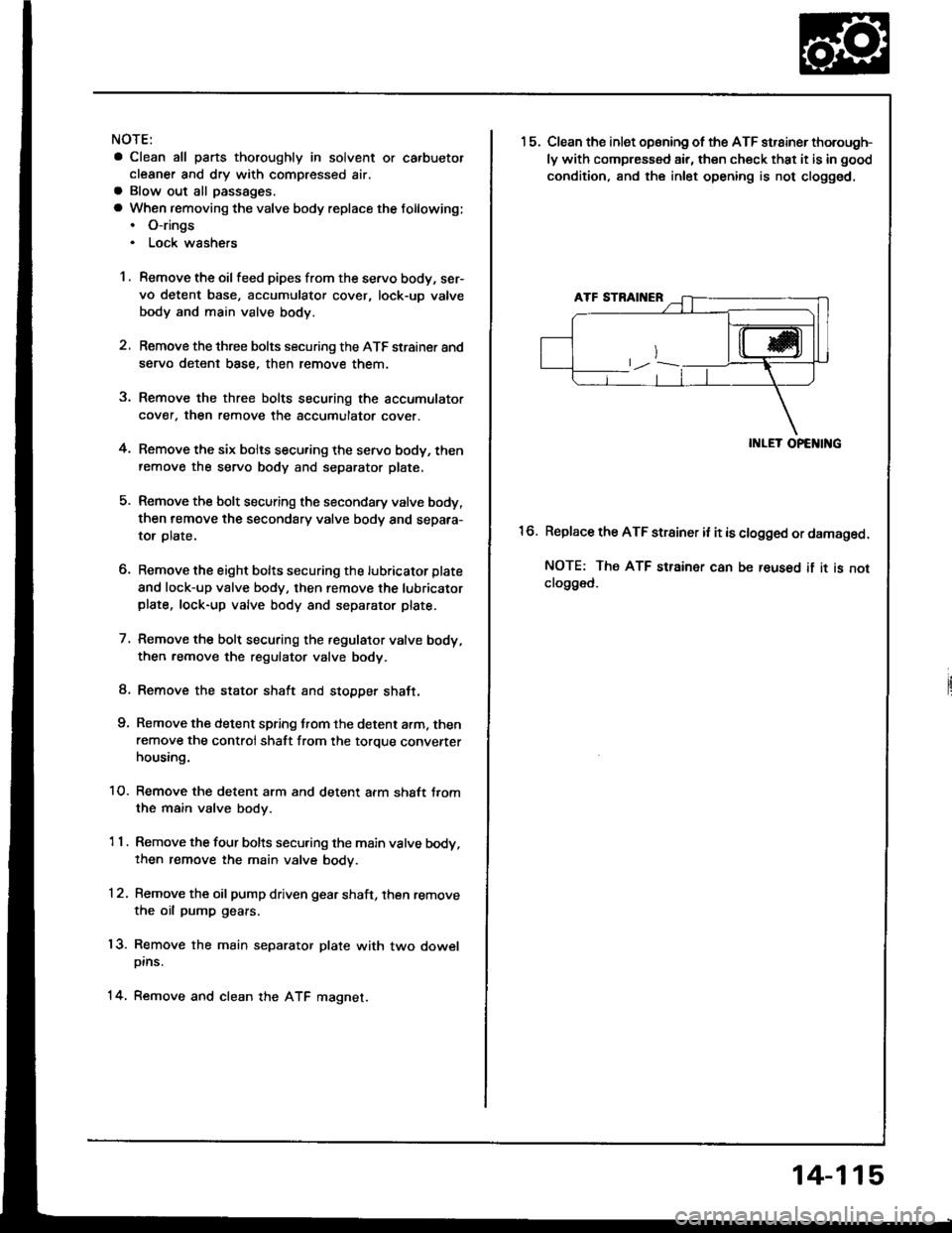
15.Clean the inlet opsning of the ATF strainer thorough-
ly with compressed air, then check that it is in good
condition, and the inlet opening is not clogged.
II{LET OPENING
Replace the ATF strainer it it is clogged or damaged.
NOTE: The ATF strainer can be reused if it is notclo9ged.
16.
14-115
Page 512 of 1413
Qr
DETENT ARM SHAFT
MANUAL VALVE
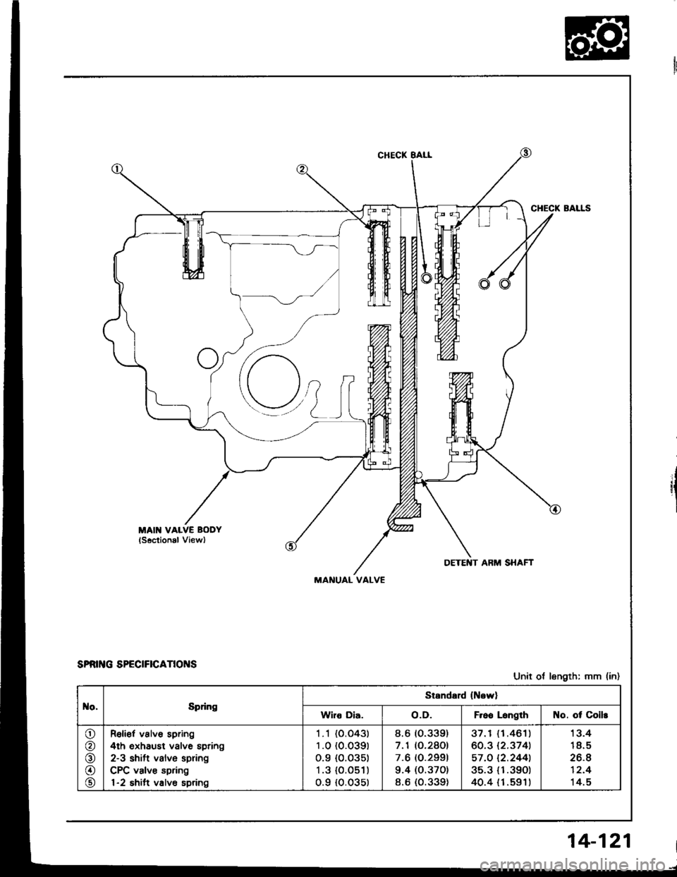
sPat G sPEctFtcaTtot{s
Unit ot length: mm (in)
o,Epfng
Standard lNowl
Wiro Dia.o.D.F.oo LsngthNo. ot Coils
o
@
o
o
@
Relief valve spring
4th oxhaust valve spring
2-3 shift valve spring
CPC valve spring
1-2 shift valv6 spring
1 .1 {O.O43l
1 .0 {0.039t
0.9 {0.035t
1.3 {O.051)
0.9 {0.03s)
8.6 (0.339)
7.1 (O.2801
7.6 (O.2991
9.4 (0.370)
8.6 (O.339)
37.1 { 1.461)
60.3 12.3741
57.O 12.2441
35.3 {1.39O)
40.4 {1.s91t
1 3.4
18.5
26.4
12.4
14.5
14-121
Page 546 of 1413
Transmission
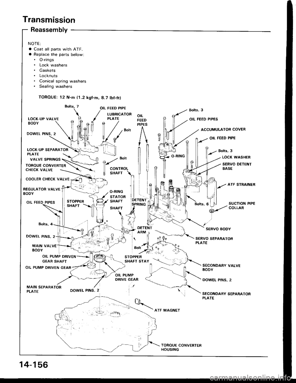
NOTE:
a Coat all parts with ATF.a Replace the parts below:. O-rings. Lock washers. Gaskets. Locknuts. Conical spring washers. Sealing washers
TOROUE: 12 N.m (1.2 kgt.m, 8.7 tbf.fr)
LOCK-UP VALVEEODY
OOWEL PINS, 2
COOLER CHECK VALVE
Reassembly
Bolts,4
DOWEL PINS. 2
MAIN VALVE
OIL FEED PIPE
/ LUBRTcAToR
, PLATE
fln /
| / /""n
v{*' e'f _\
_! 1.-...-]]
-. :-,.
OOWEL PINS, 2
orLFEEDPIPES
OIL FEED PIPES
ACCUMULATOB COVER
OIL FEED PIPE
Bolts,3
e
"o't
CONTROL
E SHAFT
LOCK WASHER
SERVO DETENTBASE
REGULATOR VALVEBODY
OIL FEED PIPES
SERVO BODY
SERVO SEPARATORPLATE
EoDY | . "1-
OIL PUMP DRIVEN
GEAR SHAFT
OIL PUMP DRIVEN GEAR
MAIN S€PARATORPLATE
SECONDARY VALVEBODY
DOWEL PINS, 2
SECONDARY SEPARATORPLATE
vaLVE spRtNGS \_(< \
ToRou E coN vE RTE n \-\.--CHECK VALVE ----.-. --'r -
Bolt
14-156
ATF MAGNET
Page 547 of 1413
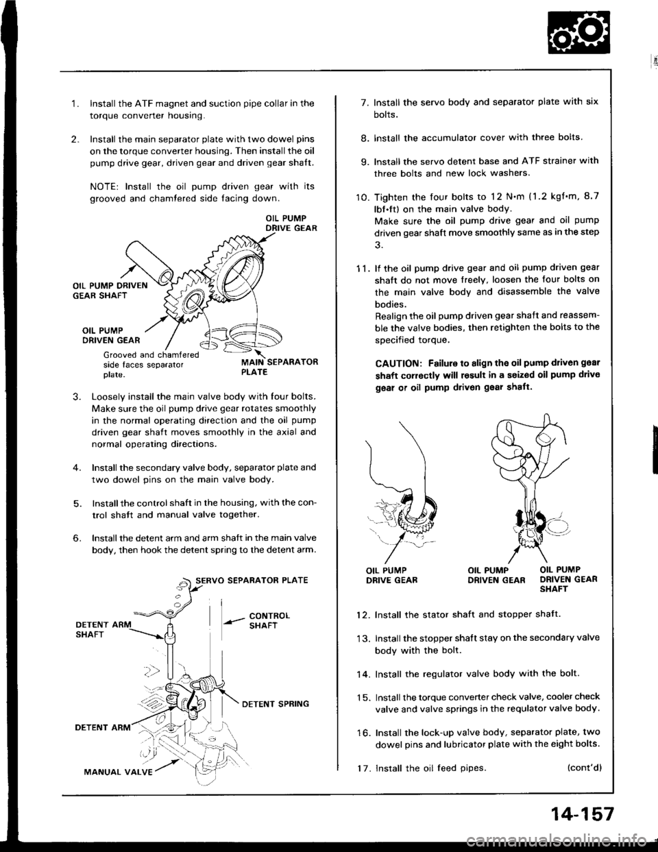
2.
1.Install the ATF magnet and suction pipe collar in the
torque converter nousrng.
Install the main separator plate with two dowel pins
on the torque converter housing. Then install the oil
pump drive gear, driven gear and driven gear shalt.
NOTE| Install the oil pump driven gear with its
grooved and chamtered side facing down.
OIL PUMPDRIVE GEAR
OIL PUMPORIVEN GEAR
Grooved and chamferedside faces separatorplate.
J.Loosely install the main valve body with Iour bolts.
Make sure the oil pump drive gear rotates smoothly
in the normal operating direction and the oil pump
driven gear shaft moves smoothly in the axial and
normal operating directaons.
Install the secondary valve body, separator plate and
two dowel pins on the main valve body.
Installthe control shaft in the housing, with the con-
trol shatt and manual valve togelher.
Install the detent arm and arm shatt in the main valve
body, then hook the detent spring to the detent arm.
SERVO SEPARATOR PLATE
--- 8ixli"'
6.
36
DETENTSHAFT
DETENT ARM
MANUAL VALVE
DETENI SPRING
17. Install the oil feed pipes.
14-157
E'.:
7. Install the servo body and separator plate with six
bolts.
8. lnstall the accumulator cover with three bolts
9. lnstall the servo detent base and ATF strainer with
three bolts and new lock washers.
10. Tighten the four bolts to 12 N.m (1.2 kgf'm, 8.7
lbf.ft) on the main valve body.
Make sure the oil pump drive gear and oil pump
driven gear shaft move smoothly same as in the step
11. lf the oil pump drive gear and oil pump driven gear
shaft do not move freelY. loosen the four bolts on
the main valve body and disassemble the valve
bodies.
Realign the oil pump driven gear shaft and reassem-
ble the valve bodies, then retighten the bolts to the
specified torque,
CAUTION: Failure to align the oil pump d1iv6n gear
shaft corroctly will result in a seized oil pump drivo
geal of oil pump drivon gear shatt.
l\
(...l
=..�N
L,1ffi#
j-*/:
OIL PUMPDRIVE GEABOIL PUMP OIL PUMPDRIVEN GEAR DRIVEN GEARSHAFT
12. Install the stator shaft and stopper shatt.
13. Install the stopper shatt stay on the secondary valve
body with the bolt.
14. Install the regulator valve body with the bolt.
1 5. Install the torque converter check valve, cooler check
valve and valve springs in the requlator valve body.
16. Install the lock-up valve body, separator plate, two
dowel pins and lubricator plate with the eight bolts.
(cont'dl