reset HONDA INTEGRA 1998 4.G Workshop Manual
[x] Cancel search | Manufacturer: HONDA, Model Year: 1998, Model line: INTEGRA, Model: HONDA INTEGRA 1998 4.GPages: 1681, PDF Size: 54.22 MB
Page 238 of 1681
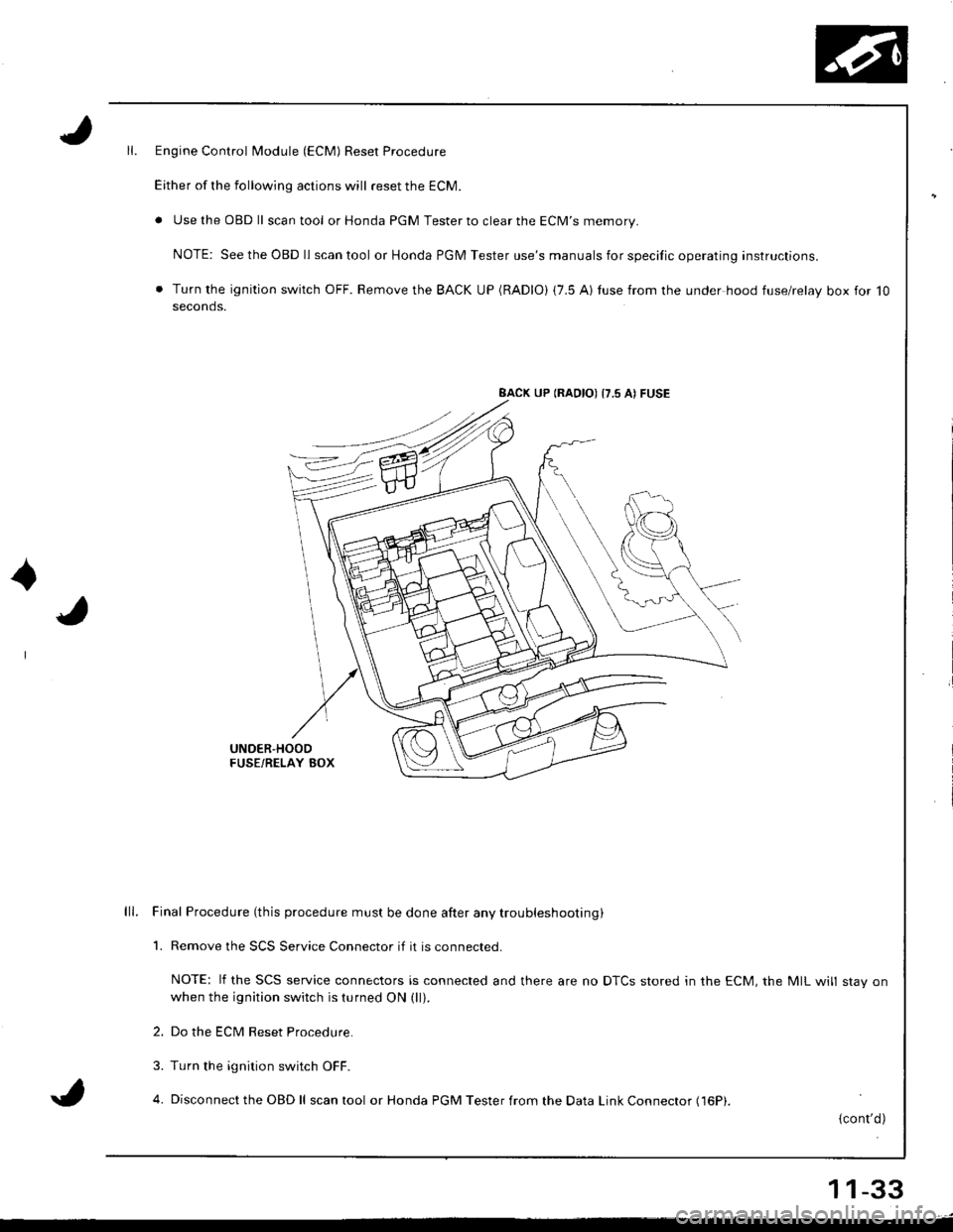
Engine Control Module (ECM) Reset Procedure
Either of the following actions will reset the ECM.
. Use the OBD ll scantool or Honda PGM Tester to clear the ECM'S memory.
NOTE: See the OBD ll scan tool or Honda PGM Tester use's manuals for specific operating instructions.
. Turn the ignition switch OFF. Remove the BACK UP (RADIO) (7.5 AI tuse from the under hood fuse/relay box for 10seconds.
BACK UP (RAOIO) {7.5 AI FUSE
UNDER'HOODFUSE/RELAY BOX
lll. Final Procedure (this procedure must be done after any trou bleshooting )
1. Remove the SCS Service Connector if it is connected.
NOTE: lf the SCS service connectors is connected and there are no DTCS stored in the ECM, the MIL will stav onwhen the ignition switch is turned ON (ll).
2. Do the ECM Reset Procedure.
3. Turn the ignition switch OFF.
4. Disconnect the OBD ll scan tool or Honda PGM Tester from the Data Link Connector (16P|.
{cont'd)
11-33
Page 252 of 1681
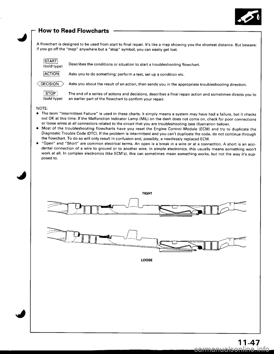
How to Read Flowcharts
A flowchart is designed to be used from start to final repair. lt's like a map showing you the shone$ distance. But beware:if you go off the "map" anywhere but a "stop" symbol, you can easily get lost.
FTARN(bold type)
FcroNl
@>
sroFl
(bold type)
NOTE:
. The term "lntermittent Failure" is used in these chans. lt simply means a system may have had a failure, but it checksout OK at this time. lf the Malfunction lndicator Lamp (MlL) on the dash does not come on, check for poor connectionsor loose wires at all connectors related to the circuit that you are troubleshooting (see illustration below).. Most of the troubleshooting flowcharts have you reset the Engine Control Module (ECM) and try to duplicate theDiagnostic Trouble Code (DTC). lf the problem is intermittent and you can't duplicate the code, do not continue throughthe flowchart. To do so will only result in confusion and, possibly, a needlessly replaced ECM.. "Open" and "Short" are common electrical terms. An open is a break in a wire or at a connection. A short is an acci-dental connection of a wire to ground or to another wire. In simple electronics, this usually means something won,twork at all. In complex electronics (like ECM's), this can sometimes mean something works, but not the way rr s sup-posed 10.
Describes the conditions or situation to start a troubleshootinq flowchart
Asks you to do something; perform a test, set up a condition etc.
Asks you about the result of an action, then sends you in the appropriate troubleshooting direction.
The end of a series of actions and decisions, describes a final repair action and sometimes direcls you toan earlier part of the flowchart to confirm your repair.
11-47
Page 272 of 1681
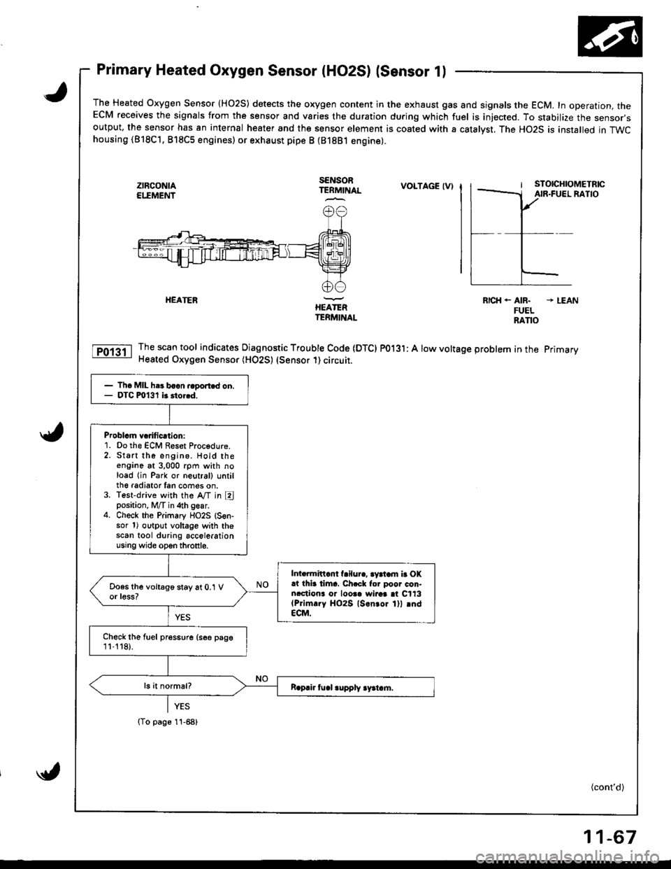
Primary Heated Oxygen Sensor (HO2S) lsensor 1l
The Heated Oxygen Sensor {HO2S) detects the oxygen content in the exhaust gas and signals the ECM. In operation, theECM receives the signals from the sensor and varies the duration during which fuel is iniected. To stabilize the sensor,soutput, the sensor has an internal heater and the sensor element is coated with a catalyst. The HO2S is installed in TWChousing (818C'1, 818C5 engines) or exhaust pipe B {81881 engine).
ztFcoNtAEI."EMEI'IT
SENSORTERMINALVOLTAGE IV)
HEATERIIEATERTERMINAL
RICH. AIR. * LEANFUELRANO
Thescantool indicates Diagnostic Trouble Code IDTCI PO13l: A low voltage problem in the primary
Heated Oxygen Sensor (HO2S) (Sensor 1) circuit.
- Th6 MIL h.r baan.ago.t.d on.- DTC m131 it 3to..d.
Problcm vcrificrtion:1. Do the ECM Reset Procedure.2. Start the engino. Hold theengane at 3,000 rpm with noload lin Park or neutral) untilth€ radiator Ian cofies on.3. Test-drive with the A,/T in Eposition, M/T in 4th gear.4. Check the Primary flO2S {S€n-sor 1) output voltage with thescan tool during accelerationusing wide open throttle.
Intarmittcnt f.ilur., 3yatam b OK.t thia tima. Ch.ck for poor con.nrctiona or loosa wiraa at C113(Prim.ry HO2S ls.n.or lll rndECM.
Chock the fuel pres6ure (see psge11-'t 18).
{To page 11-68)
(cont'd)
11-67
Page 274 of 1681
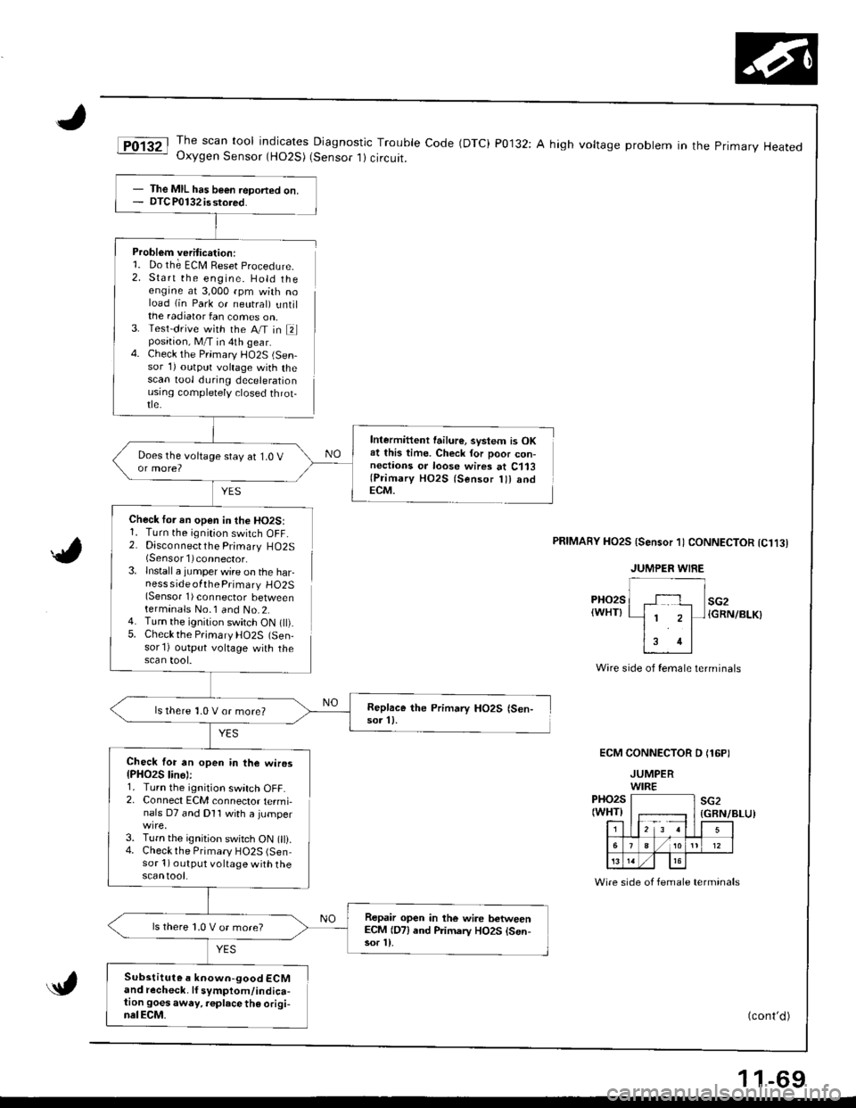
JThe scan tool indicates Diagnostic Trouble Code (DTC) P0132: A high voltage probtem in the primary HeatedOxygen Sensor (HO2S) (Sensor 1) circuit.
Problem veritication:1. Do th; ECM Reset procedure.
2. Start the engine. Hold theengine at 3,000 rpm with noload (in Park or neutral) untilthe radiator fan comes on,3. Test-drive with the A/T in Elposition, M/T in 4th gear.4. Check the Primary l-lO2S (Sen-sor 1) outprrt voltage with thescan tool during decelerationusrng comptetely closed throt-tle.
YES
Check tor an open in the HO2S:1. Turn the ignition switch OFF.2. Disconnectthe Primary HO2S(Sensorl)connector.
lnstall a jumper wire on the harness side ofthe Primary HO2S(Sensor 1) connector betweenterminals No.1 and No.2.Turn the ignition switch ON t).Check the Prjmary HO2S (Sen-sor'l) output voltage with thescan tool.
Intermittent failur€, svstem is OKat this time. Check for poor con-nectaons or loose wires at C113(Primary HO2S lsensor lll andECM.
5.
PRIMAnY HO2S {Sensor 1) CONNECTOR tC1t3l
PHO2S(WHT}
Wire side of female terminals
ECM CONNECTOR D (16PI
JUMPERWIREPHO2S(WHT)F;r=12 3 !l
sG2
5
./ 1012
13
(GBN/BLU)
Wire side of female terminals
(cont'd )
- The MIL has b€€n ieDorted on.- DTC P0132 isstored.
Replace the Primary HO2S (Sen-sor 11.ls there 1,0 V or more?
Check for an open in the wiros{PHO2S lin6):1. Turn the ignition switch OFF.2. Connect ECM connector termi-nals D7 and Dl1 with a jumper
3. Turn the ignition switch ON 0).4. Checkthe Primary HO2S (Sen-sor 1) output voltage with thescantool.
Repair open in the wire betweenECM (D7) end Primarv HO2S lsen-sor l).
ls there 1,0 V or more?
Substitute a known-good ECMand recheck. lf symptom/indica-tion goesaway. r€place th€ origi-nalECM.
1 1-69
Page 275 of 1681
PGM-FI System
Primary,Heated Oxygen Sensor (HO2S) (Sensor 1) (cont'dl
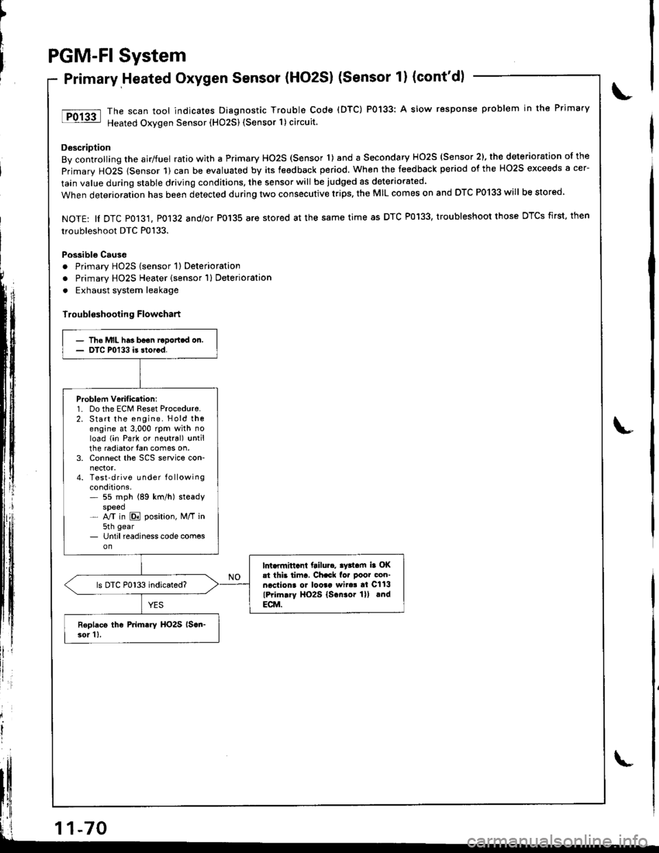
The scan tool indicates Diagnostic Trouble Code (DTC) P0133: A slow response problem in the Primary
Heated Oxygen Sensor (HO25) (Sensor 1) circuit.
Description
By controlling the airlfuel ratio with a Primary HO2S (Sensor 'l) and a Secondary HO2S (Sensor 2), the deterioration of the
primary HO2S {Sensor 1) can be evaluated by its teedback period. When the feedback period of the HO2S exceeds a cer-
lain value during stable driving conditions, the sensor will be judged as deteriorated.
When deterioration has been detected during two consecutive trips, the MIL comes on and DTC P0133 will be stored
NOTE: ll DTC P013't, P0132 and/or P0'135 are stored at the same time as DTC P0133, troubleshoot those DTCS first, then
troubleshoot DTC P0133.
Possible Cause
. Primary HO2S (sensor 1) Deterioration
o Primary HO2S Heater (sensor 1) Deterioration
. Exhaust system leakage
Troubl€shooting Flowchart
')
litll r
- Tho MIL has boon raDortcd on.- DTC P0133 is storcd.
Problem verificttion:1. Do the ECM Reset Procedure.2. Start the engine. Hold thoengine at 3,000 rpm with noload (in Park or neutral) untilthe radiator fan comes on.3. Connect the SCS service con-
4. Test'drive Lrnder f o llowingconditions.* 55 mph (89 km/h) steadyspeed- NT in E position, M/T in5th gear- Until readiness code com€son
lnt.flnittcnt ftilu... ay3tam ia OKat thb tiinr. Ch.ck fo. poor con-necliona o. looaa wita! al Cll3
lPrim.ry HO2S lscn.or lll lndECM.
ls DTC P0133 indicated?
Roplacs the Primary HO2S lscn-3or 1),
Page 276 of 1681
Secondary Heated Oxygen Sensor (HO2S) {sensor 2l
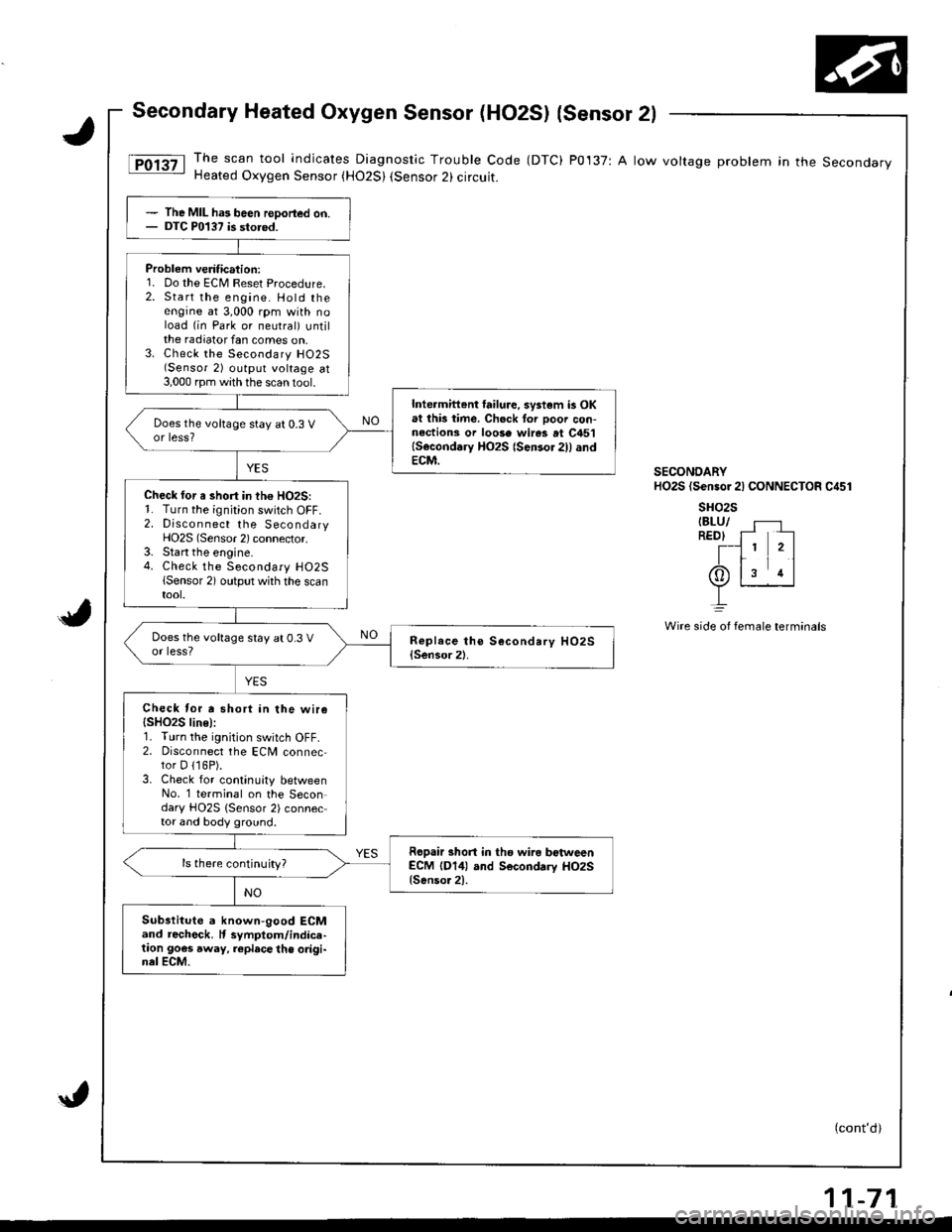
The scan tool indicates Diagnostic Trouble Code (DTC) P0137: A low voltage problem in the SecondaryHeated Oxygen Sensor (H02S) (Sensor 2) circuit.
(cont'd)
The MIL ha3 been reDorted on.DTC P0137 is storod.
Problem veritication:1. Do the ECM Reset Procedure.2. Start the engine. Hold theengine at 3,000 rpm with noload (in Park or neutral) untilthe radiator fan comes on,3. Check the Secondary H02S(Sensor 2) output voltage at3,000 rpm with the scan 1ool.
Inte.mittent failure, system is OKat lhb time. Ch6ck Ior ooor con-nections or loose wires at C451lSeconddry HO2S {Sensor 2)l andECM.
Does the voltage stay at 0.3 Vor less?
Check for a short in th€ HO2S:1. Turn the ignition switch OFF.2. Discon nect the SecondaryHO2S (Sensor 2) connector.3. Start the engine.4. Check the Secondary H02S(Sensor 2) output whh the scantool.
Does the voltage stay at 0.3 Vor less?
Check tor a short in the wire{SHO2S line):r. I urn rne rgnt on swttch uFF,2. Disconnect the ECM connec,tor D 116P).3. Check for continuity betweenNo. '1 terminal on the Secon-dary HO2S {Sensor 2) connector and body ground.
Ropair short in tho wira bctweenECM (D14) and Secondrry HO2S{Senso.2).
ls there continuity?
Substitute a known-good ECMand recheck. It symptom/indice-taon goes away, replace the origi-nel ECM.
SECONDARYHO2S (Sensor 2l CONNECTOR C451
sHo2sIBLU/REDI f- --
T-l 1 2ltr11(Or ls rl
L
Wire side oI fernale terminals
11-71
Page 277 of 1681
PGM-FI System
Secondary Heated Oxygen Sensor (HO2S) (Sensor 2l (cont'd)
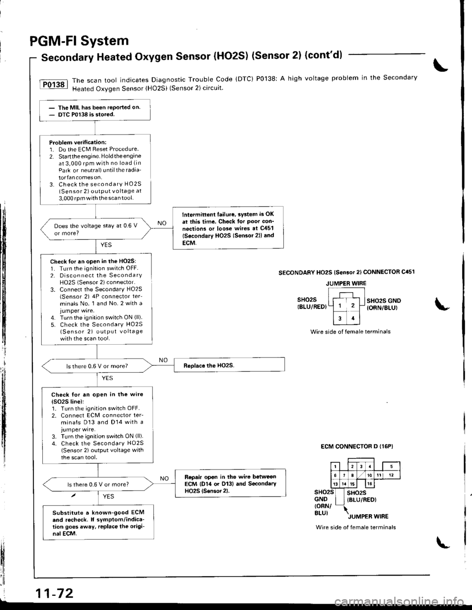
The scan tool indicates Diagnostic Trouble Code (DTC) P0138: A high voltage probiem in the Secondary
Heated Oxygen Sensor {HO2Si (Sensor 2) circuit.
YES
The MIL has been reported on.DTC P0138 is stored.
Problem verification:1. Do the ECM Reset Procedure2. Startthe engine. Holdtheengineat 3,000 rpm with no load (in
Park or neutral) untilthe radia'
torfancomeson.3. Check the secondary HO2S(Sensor 2) outPUt vo ltage at
3,000 rpm withthe scan tool.
lntermittent lailur€, svsted i3 OK
at this time. Chock tor Poor con'
nections or loo3e wires at C451
lSecondary HO2s lsensor 2ll and
ECM,
Does the voltage stay at 0.6 V
ls there 0.6 V or more?
Check for an open in the wite
{s()2S line):1. Turn the ignition switch OFF.2. Connect ECM connector ter-minals D13 and Dl4 with ajumper wire.3. Turn the ignition switch ON (ll).
4. Check the Secondary HO25(Sensor 2) output voltage withthe scan tool,
Repair opsn in the wire b€tweonECM {D14 or O13} and SecondaryHO2S {Sensor2).ls there 0,6 V or more?
Substitute a known-good ECMend r6check. It symptom/indica-tion goes away, rcplace the origi-nal ECM.
tI
t$
ffi
tljl'l
t,
lfi
il
fl'I
Check for an open in the HO2S:1. TLrrn the ignition switch OFF.2. Disconnect the SecondaryH02S (Sensor 2) connector.
3. Connect the Secondary HO2S(Sensor 2) 4P connector ter_
minals No. 1 and No.2 with ajumper wire.4. Turn the ignition switch ON (ll).
5. Check the Secondary HO25(Sensor 2) output vo lta ge
with the scan tool.
SECONDAFY HO2S {Sensor 2l CONNECTOR C451
sHo2sIBLU/REDIsHo2s GNOIONN/BLUI
Wire side of female terminals
ECM CONNECTOR D I16P}
sHo2sGND{ORN/BLUI
sHo2sIBLU/RED)
Wire side of female terminals
JUMPER WIRE
i 11-72L
Page 278 of 1681
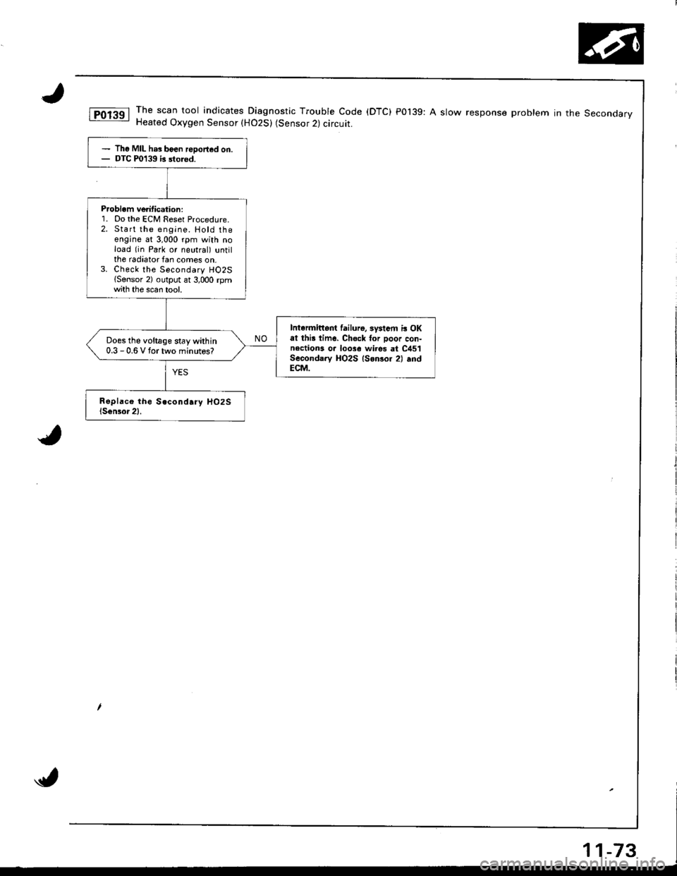
The scan tool indicates Diagnostic Trouble Code (DTC) P0139: A slow response problem in the SeconoarvHeated Oxygen Sensor (H02S) (Sensor 2) circuit.
The MIL has boen reDorted on.DTC P0139 b sto.od.
P.oblem ve tication:1. Do the ECM Reset Procedure.2. Start the engine. Hotd theengine at 3,000 rpm with noload (in Park or neutral) untilthe radiator fan comes on,3. Check the Secondary HO2S{Sensor 2) output ar 3,000 rpmth the scan tool.
Intarmittert lailurg, systsm i! OKat thi! time. Chsck for Door con-nections o. loose wi.es at C451Secondary HO2S lsonsor 2) .ndECM.
Does the voltage stay within0.3 - 0.6 V tortwo minutos?
Page 279 of 1681
PGM-FI System
Heated Oxygen Sensor (HO2S) Heater
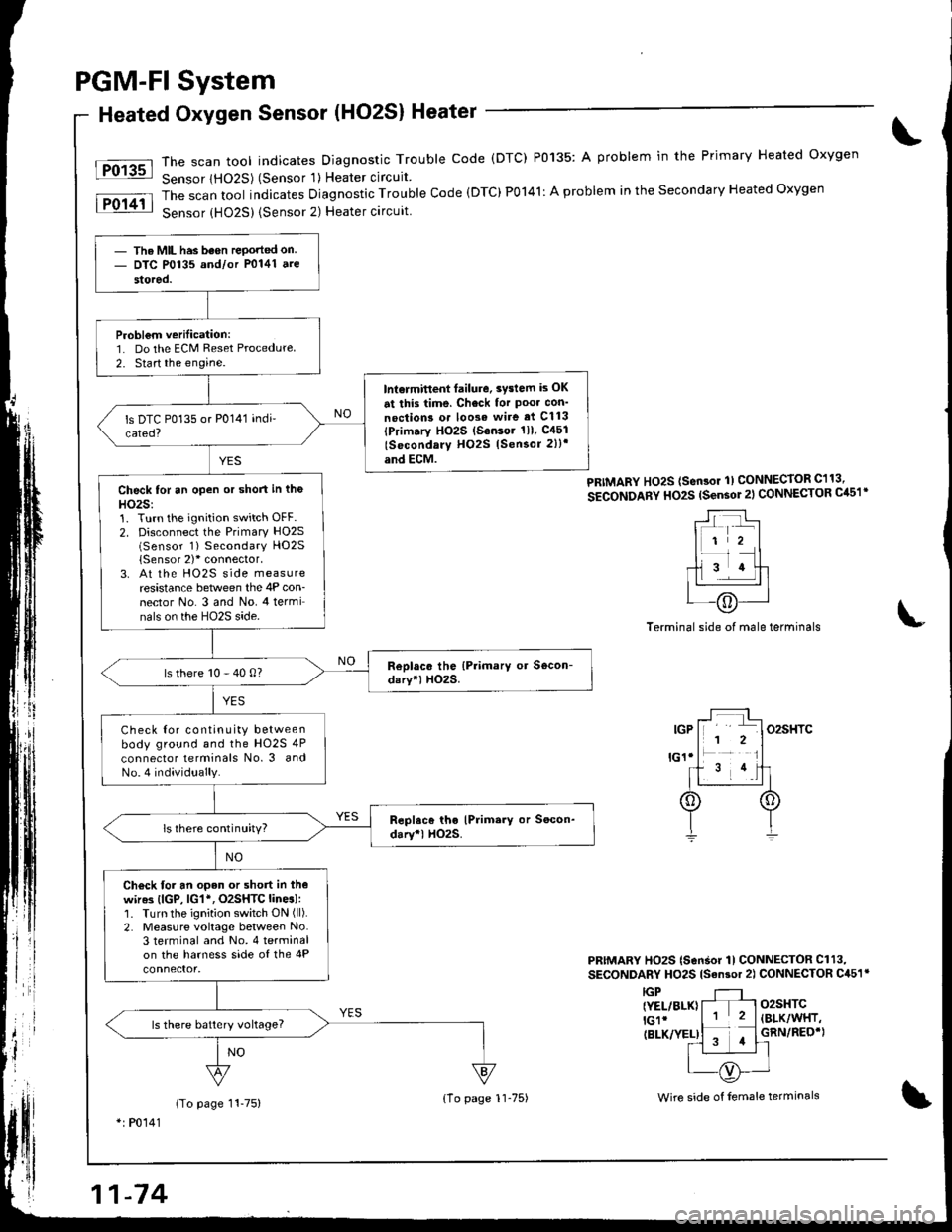
The scan tool indicates Diagnostic Trouble code (DTC) P0135: A problem in the Primary Heated oxygen
Sensor lHO2S) (Sensor 'l) Heater circuit
The scan tool indicates Diagnostic Trouble Code (DTC)P0141: A problem in the Secondary Heated Oxygen
Sensor {HO25) {Sensor 2) Heater circuit
Fo13sl
lFol4il
PRIMARY Ho2S (sen3or 1) CONNECToR C113,
SECONDARY HO2S (sensor 2l CONNECTOR Cil51'
Terminal side of male terminals
PRIMARY HO2S (SonSor 1l CONNECTOR Cl13,
SECONDARY HO2S lsan3or 2) CONNECTOR C451r
o2sHTC(BLK/WHT,
GRN/REO'}
IGP{YEL/BLK}lGlr(BLK/YEL)
(To page 11-75)*: P0141
- The MIL has been rePorted on- DTC P0135 and/or P0141 ate
stored.
Probl€m verilication:1. Do the ECM Reset Procedure
2. Start the engine.
lnt€rmitlent failure. 3vslem is OK
at this time. Check for Poo. con'
noction3 o. loose wire ai Cl13(Primary HO2S (S.nsor 1ll. gl51
lSocondary H02S lSensor 2))'
and ECM.
Check for an open or short in tho
HO2S:1. Turn the ignition switch OFF.2. Disconnect the Primary HO2S(Sensor 1) Secondary HO2S
{Sensor 2)'connector,3. At the HO2S side measureresistance between the 4P con-nector No. 3 and No. 4 terminals on the HO2S side.
ls there 10 - 40 0?
Check Ior continuity betweenbody ground and the HO2S 4P
connector lerminals No. 3 andNo.4 individually.
ls there continuity?
Ch€ck for an open or short in thewir63 (lGP, lG1*, O2SHTC lines):1. Turn the ignition switch ON (ll).
2. Measure voltage between No.3 terminal and No. 4 terminalon the harness side of the 4P
ls there batlery vohage?
{1o page 1l-75)Wire side of female terminals
Page 285 of 1681
PGM.FI
Misfire
System
Detected in One Cylinder (cont'd)
)
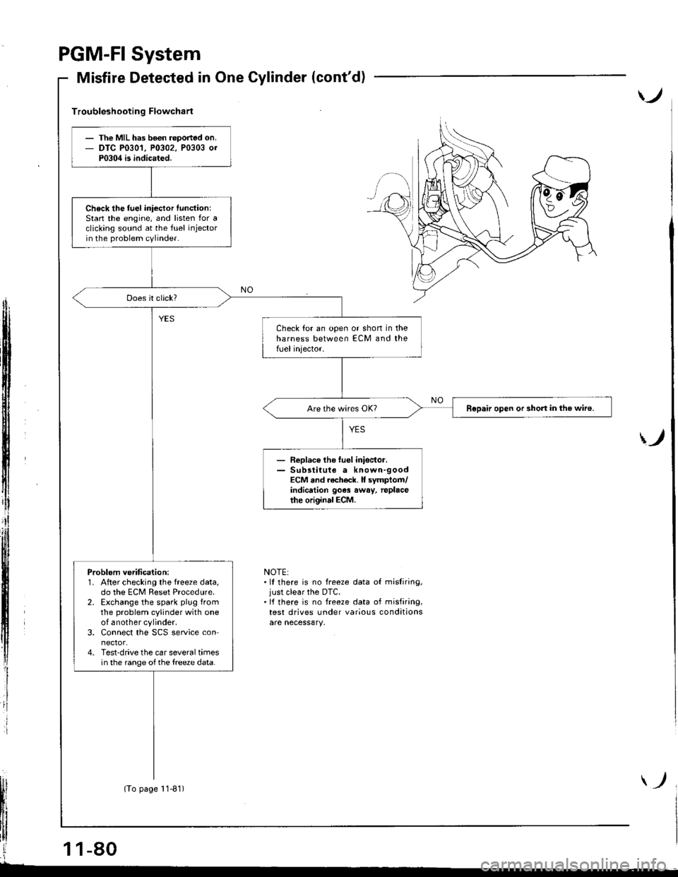
Troubleshooting Flowchart
ff
i
)
NOTE:.lf there is no freeze data of misliring,just clear the DTC.'lf there is no freeze data of misfiring,test drives under various conditions
The MIL has b6€n reported on.DTC P0301, P0302, P0303 0rP0304 is indicated.
Check the fuel iniector function:Stan the engine, and listen for aclicking sound at the fuel injectorin the problem cylinder.
Check for an open or shon in theharness between ECM and thefUel injector.
Repair open or short in the wiro.
- Replace tho luel inisctor.- Sub3titute a known-goodECM and rach€ck. It symptom/indicrtion 90e3 away, replacethe original ECM.
Problem ve.ification:1. After checking the freeze data,do the ECM Reset Procedure.2. Exchange the spark plug fromthe problem cylinder with oneof another cylinder.3. Connect the SCS service connector.4. Test-drive the car several timesin the range of the treeze data.
(To page 11-81)