reset HONDA INTEGRA 1998 4.G Owner's Manual
[x] Cancel search | Manufacturer: HONDA, Model Year: 1998, Model line: INTEGRA, Model: HONDA INTEGRA 1998 4.GPages: 1681, PDF Size: 54.22 MB
Page 323 of 1681
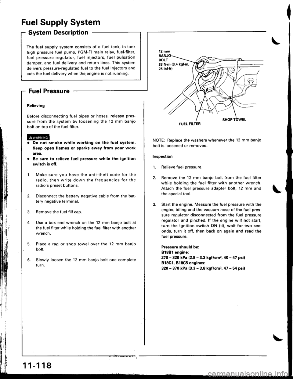
The fuel supply system co
high pressure fuel pump, t
fuel pressure regulator. f
damper, and fuel delivery i
delivers pressure-regulated
cuts the luel delivery when
Fuel Supply System
System Description
consists of a fuel tank, in-tank
r, PGM-Fl main relay, fueffilter,
. fuel injectors, fuel pulsation
y and return lines. This system
ed fuel to the fuel injectors and
rn thq engine is not running.
Fuel Pressure
Relieving
Before disconnecting fuel pipes or hoses, release pres-
sure from the system by loosening the 12 mm banjo
bolt on top ol the fuel filter.
Do not smok€ while working on the tuel system,
Keep open flames or sparks away from you. work
arga.
Be sure to relieve fuel pressure while the ignition
swiich is ofl,
Make sure you have the anti theft code for the
radio, then write down the frequencies for the
radio's preset buttons.
Disconnect the battery negative cable from the bat-
tery negative terminal.
Remove the fuelfill cap.
Use a box end wrench on the 12 mm banjo bolt at
the fuel filter while holding the fuel filter with another
wrench.
Place a rag or shop towel over the '12 mm banjo
bolt.
Slowly loosen the 12 mm banjo bolt one complete
tu rn.
1 1-1 18
I
NOTE| Replace the washers whenever the 12 mm banjo
bolt is loosened or removed.
lnsDection
1. Relieve fuel pressure.
2. Remove the 12 mm banjo bolt from the fuel filter
while holding the fuel tilter with another wrench.
Attach the fuel pressure adapter bolt, 12 mm and
the special tool.
3. Stan the engine. Measure the tuel pressure with the
engine idling and the vacuum hose of the fuel pres-
sure regulator disconnected from the fuel pressure
regulator and pinched. lf the engine will not start,
turn the ignition switch ON (ll), wait for two sec-
onds, turn it off, then back on again and read the
tuel pressure.
Pressuro should be:
Bl8Bl engire:
270 - 320 kP. (2.8 - 3.3 kgl/cm'�.40 - 47 psi)
818C1, 818C5 engines:
320 - 370 kPa (3.3 - 3.8 kgt/cm'�. 47 - g psi)
12 mm
FUEL FILTER
Page 344 of 1681
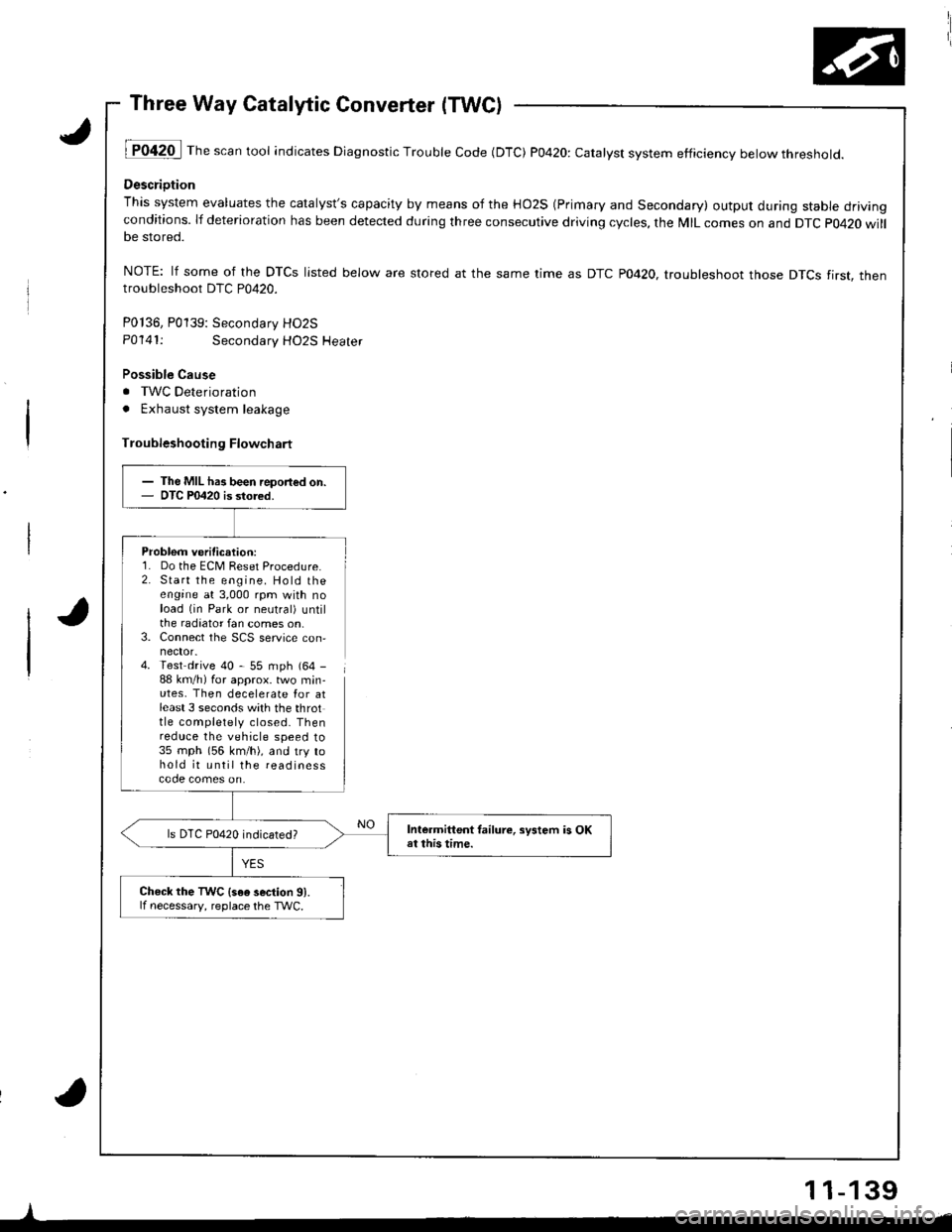
Three Way Catalytic Converter (TWC)
lT042O I Th" """n tool indicates Diagnostic Trouble Code (DTC) P0420: catatyst system efficiency below threshold.
Descriotion
This system evaluates the catalyst's capacity by means of the HO2S (Primary and Secondary) output during stable drivingconditions. lf deterioration has been detected during three consecutive driving cycles, the MIL comes on and DTC p0420 willbe stored.
NOTE: lf some of the DTCS listed below are stored at the same time as DTC PO42O. troubleshoot those DTCS tirst. thentroubleshoot DTC P0420.
P0136, P0139: Secondarv HO2S
P0141:Secondary HO2S Heater
Possible Cause
. TWC Deterioration
. Exhaust system leakage
Troubleshooting Flowchart
Problem verification:1. Do the ECM Reset Procedure.2. Start the engine. Hold theengine at 3,000 rpm with noload (in Park or neutral) untilthe radiator fan comes on,3. Connect the SCS service con,
4. Test drive 40 - 55 mph (64 -
88 km/h) for approx. two min-utes, Then decelerate Ior atleast 3 seconds with the throttle completely closed. Thenreduce the vehicle speed to35 mph (56 km/h), and try tohold it until the readinesscode comes on.
I
- The MIL has been report€d on.- OTC P0420 is stored.
Intermittent tailure, sFtem is OKat this time.ls DTC P0420 indicated?
Check the TWC {s6e 3ection 91.lf necessary, reolace the TWC.
11-139
Page 347 of 1681
lT
Emission Control System
YES
{To page 11-143}
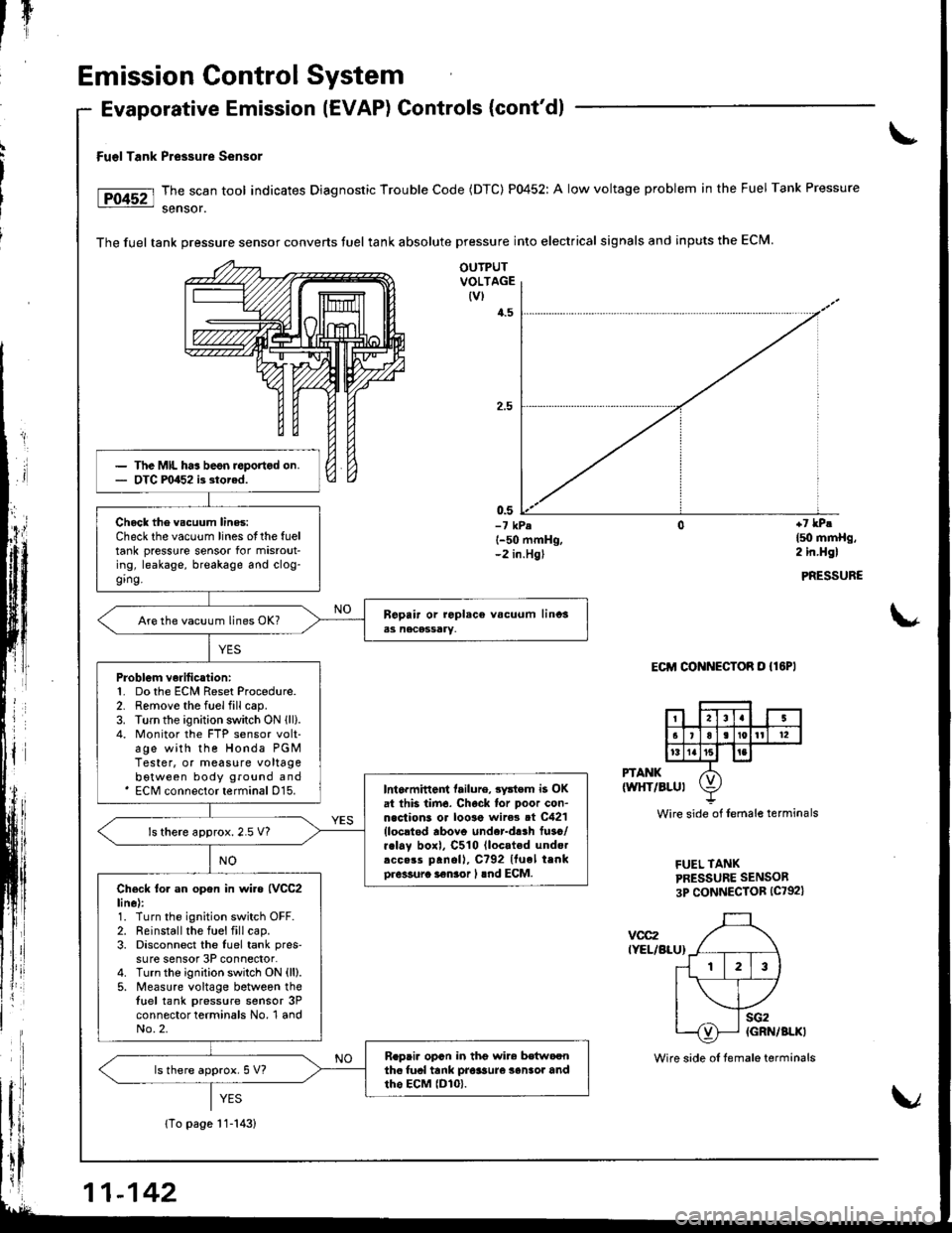
Fu€l Tank Pressure Sensor
The scan tool indicates Diagnostic Trouble Code (DTC) P0452: A low voltage problem in the Fuel Tank Pressure
sensor.
The fuel tank pressure sensor converts tuel tank absolute pressure into electrical signals and inputs the ECM.
Evaporative Emission (EVAP) Controls (cont'dl
OUTPUTVOLTAGE(vl
4.5
0.5-7 kPel-50 mmHg,-2 in.Hgl
+7 lPe
l5o mmHg,2 in.Hgl
PRESSURE
\*
Eclrl CONNECToR o {lEPl
PTANK(wltT/BLul
vcc2IYEL/BLU}
Wire side of lemale terminals
FUEL TANKPRESSURE SENSOR
3P CONNECTOR (C792)
The MIL ha3 beon roportod on.OTC F0452 i3 storad.
Chock the vscuum lines:Check the vacuum lines otthe fueltank pressure sensor for misrout-ing, leakage, breakage and clog-ging.
Are the vacuum lines OK?
Problgm verilication:1. Do the ECM Reset Procedure.2. Remove the fuel fill cap.3. Turn the ignition switch ON lll).4. Monitor the FTP sensor volt-age with the Honda PGMTester, or measure voltagebotween body ground and' ECM connector terminal D15.Int6rmittent tailure, 3ystem i3 OKat thb tirn6. Chock lor poor con-n.clions or loo3e wire3 ot C421{locltod rbovo under-d!.h fuso/r.lay boxl, C510 lloc.ted undo.rcc.rs panoll, C?92 Ituel trnko.6sura i€nior I lnd ECM.
ls there approx.2.5 V?
Check to. an opon in wi.a {VCC2line):1. Turn the ignition switch OFF.2. Reinstall the fuel fill cap.3. Disconnect the luel tank pres'su re sensor 3P connector.4. Turnthe ignition switch ON (ll).
5. Measure voltage between thetuel tank pressure sensor 3Pconnector terminals No, 1 andNo.2.
R.pai. opcn in thg wir6 bdtwoonthc fual tank pro$ure 3enlor andtho EcM lDlo).ls there approx. 5 V?
11-142
Wire side oI temale terminals
Page 349 of 1681
rI
Emission Control System
Evaporative Emission (EVAPI Controls (cont'd)
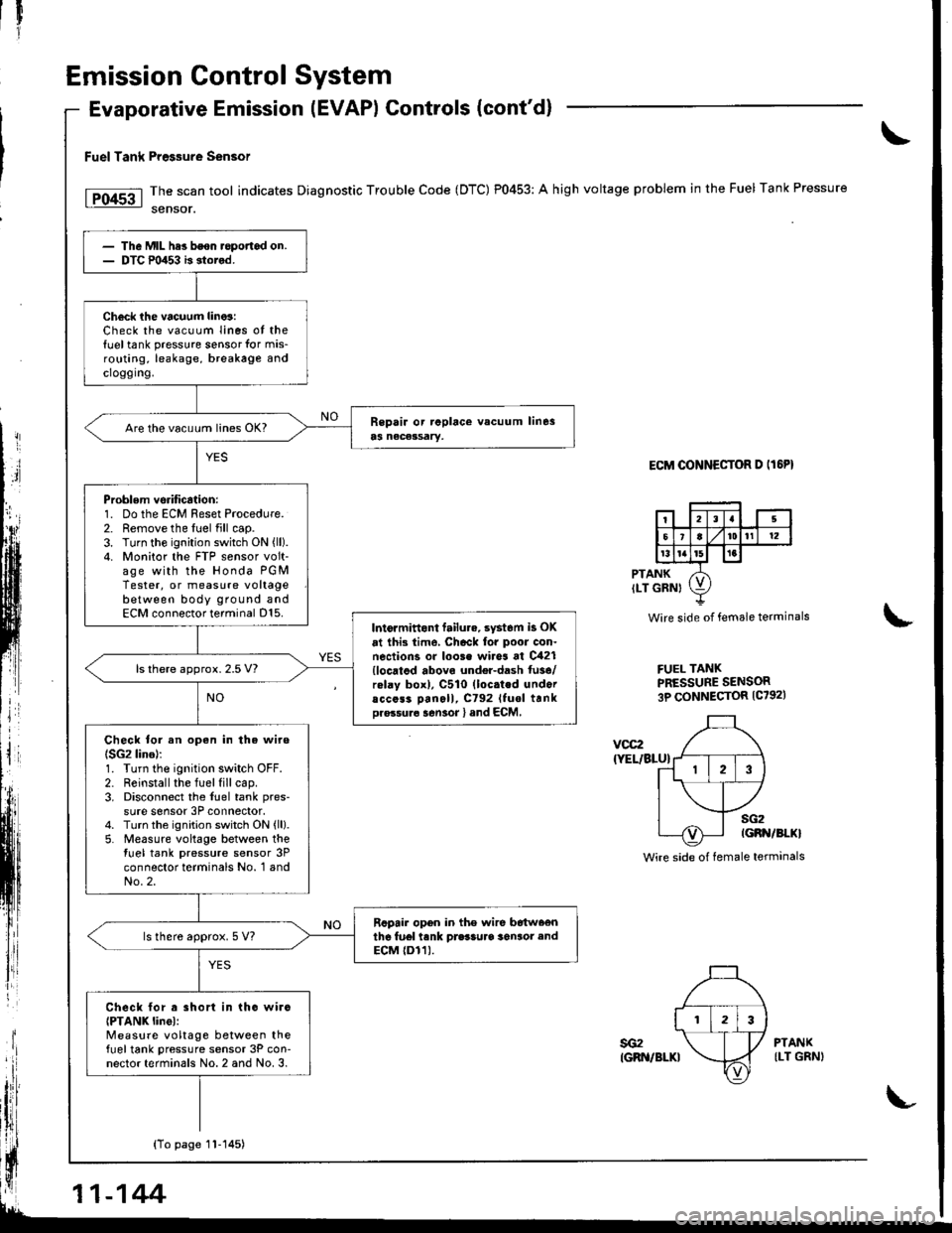
Fuel Tank Pre$ure sensor
The scan tool indicates Diagnostic Trouble Code (DTC) P0453: A high voltage problem in the Fuel Tank Pressure
sensor.
ECM OONNECTOR D IT6PI
PTANKILT GRNI
Wire side of female terminals
FUEL TANKPRESSURE SENSOR3P CONNECTOR {C7921
\
voc2
{YEL/BLU}
sG2IGBN/BI.KI
Wire side of female terminals
The Mll- hes bson.opofiad on.DTC m453 b stored.
Check ihe vacuum lino3:Check the vacuum Iines ot the{uel tank pressure sensor for mis-routing, leakage, breakage andcroggrng.
Are the vacu!m lin€s OK?
Problem vsrification:1. Do the ECM Reset Procedure.2. Remove the fuel fill cap.3. Turn the ignition switch ON {ll).4. Monitor the FTP sensor volt-age with the Honda PGMTester, or measure voltagebetween body ground andECM connector terminal D15.Intormittont failu.e. syst6m is OK
at ihi3 time, Chack for poor con.nections or loo3e wires at C421{locatod abovo undel-dash fu3e/rolay box), C510 (loc.ted undoracc6s3 Dan6ll, C792 Ituol trnkDro.su.6 sen3or l and ECM,
ls there approx. 2.5 V?
Check tor an open in the wire(SG2 lino):1. Turn the ignition switch OFF.2. Reinstall the fuel fill cap.3. Disconnect the fuel tank pres-
sure sensor 3P connector.4. Turn the ignition switch ON {ll}.5. Measure voltage between thetuel tank pressure sensor 3Pconnector terminals No. 1 andNo.2.
Rcpair opon in the wire b6tw66nthe fu6l tank prasSuaa 36n3or endECM {Dr1).ls there approx. 5 V?
Check lor a short in tho wirc{PTANK linel:Measure voltage between thefueltank pressure sensor 3P con-nector terminals No. 2 and No. 3.
YES
sG2IGRN/BLKI
PTANKILT GRNI
{To page 1l-145)
11-144
Page 467 of 1681
![HONDA INTEGRA 1998 4.G Owners Manual Troubleshooting Procedures
Checking the Diagnostic Trouble Code (DTC)
with an OBD ll Scan Tool or th€ Honda PGM Tester
When the TCM senses an abnormality in the input or output systems, the lD,] ind HONDA INTEGRA 1998 4.G Owners Manual Troubleshooting Procedures
Checking the Diagnostic Trouble Code (DTC)
with an OBD ll Scan Tool or th€ Honda PGM Tester
When the TCM senses an abnormality in the input or output systems, the lD,] ind](/img/13/6069/w960_6069-466.png)
Troubleshooting Procedures
Checking the Diagnostic Trouble Code (DTC)
with an OBD ll Scan Tool or th€ Honda PGM Tester
When the TCM senses an abnormality in the input or output systems, the lD,] indicator light in the gauge assembly will
blink. When the 16p Data Link Connector (DLC) (located under the dash on the passenger side) is connected to the OBD ll
Scan Tool or Honda PGM Taster as shown, the scan tool or tester will indicate the Diagnostic Trouble Code (DTC) when
the ignition switch is turned ON {ll}.
When the !r indicator light has been reported on, connect the OBD ll Scan Tool confirming to SAE J1978 or Honda PGM
Tester to the DLC (16P) behind the ashtray. Turn the ignition switch ON (ll) and observe the DTC on the screen ofthe OBD
ll Scan Tool or Honda PGM Tester. After determining the DTC, refer to the electrical system Symptom-to-Component
Chart on pages 14-54 and 14-55.
NOTE: SeetheOBDll ScanTool orHonda PGM Tester user's manual for specific instructions.
OBD-IlSCAN TOOL orHONDA PGM TESTER
Some PGM-Fl problems will also make the lol indicator light come on. After repairing the PGM-Fl system. disconnect the
BACK Up fuse (7.5 A) in the under-hood fuse/relay box for more than 10 seconds to reset the TCM memory, then recheck.
NOTE: Disconnecting the BACK UP fuse also cancels the radio anti-theft code, preset stations and the clock setting. Get
the customer's code number, and make note of the radio presets before removing the fuse so you can reset them
uJ trr
ulu
ai
14-50L
DATA LINK CONNECTOR (16P)
I
il
lt
rJq
Page 468 of 1681
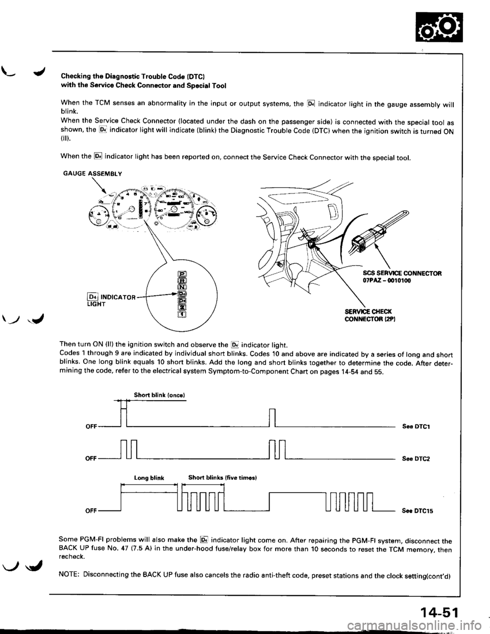
L./Checking th€ Diagnostic Trouble Codo (DTC)
with the Sowica Check Connector and Special Tool
When the TCM senses an abnormality in the input or output systems, the [D;l indicator light in the gauge assembly willblink.
When the Service Check Connector (located under the dash on the passenger side) is connected with the special tool asshown, the E1T indicator light will indicate (blink) the Diagnostic Troubte Code (DTC) when the ignition switch is turned ON{
}.
When the @ indicator light has been reported on, connect the Service Check Connector with the special toot.
GAUGE ASSEMEI.Y
Then turn ON (ll) the ignition switch and observe the E indicator light.Codes 1 through 9 are indicated by individual short blinks. Codes 1O and above are indicated by a series of long and shortblinks. One long blink equals 10 short blinks. Add the long and short blinks together to determine the code. After deter-mining the code, refer to the electrical system Symptom-to-Component Chart on pages 14-S4 and 55.
\-F;ii^r
) ,J
Se. OTCI
Soo DTC2
Long blinkShort blinb lfive timcsl
Soe DTCl5
Some PGM-FI problems will also make the E indicator light come on. After repairing the PGM-FI system, dasconnect theBACK UP fuse No. 47 (7.5 A) in the under-hood tuse/relay box for more than 1O seconds to reset the TCM memory, thenrecnecK.
NOTE; Disconnecting the BACK UP fuse also cancels the radio anti-theft code, preset stations and the clock setting(cont,d)
Short blink loncsl
\-/ \i,
14-51
Page 470 of 1681
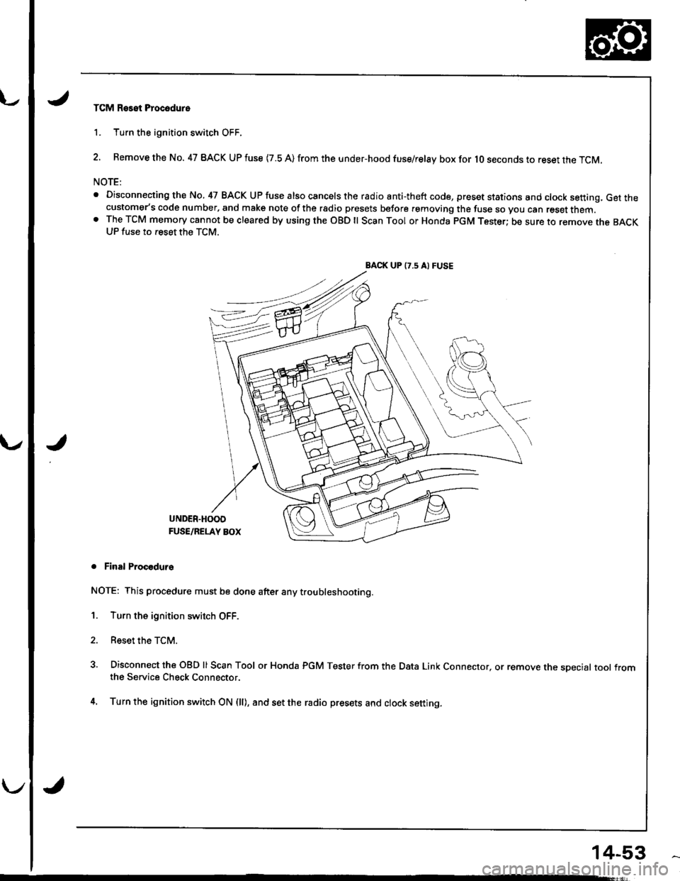
TCM Reset Procodure
1. Turn the ignition switch OFF.
2. Remove the No. 47 BACK UP fuse {7.8 A) from the under-hood fuse/relay box for lO seconds to reset the TCM.
NOTE:
. Disconnecting the No, 47 BACK UP fuse also cancels the radio anti-theft code, preset stations and clock setting, Get thecustomer's code number, and make note of the rsdio presets before removing the fuse so you can reset them.o The TCM memory cannot be cleared by using the OBD ll Scan Tool or Honda pGM Tester; be sure to remove the BACKUP fuse to reset the TCM.
BACK UP (7.5 A) FUSE
J
UNDER.HOOD
FUSE/RELAY BOX
. Final Procodurs
NOTE: This procedure must be done after any trou bleshooting.
1. Turn the ignition switch OFF.
2. Reset the TCM.
3. Disconnect the OBD ll Scan Tool or Honda PGM Tester from the Data Link Connector, or remove the sDecial tool fromthe Service Check Connector.
4. Turn the ignition switch ON (ll), and set the radio presets and clock setting.
14-53
Page 472 of 1681
u.drrf,,
J
J
J
14-55
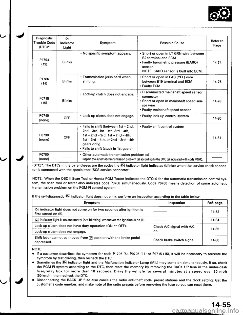
Diagnostic
Trouble Code(DTC).
Ej
lndicator
Light
SymptomPossible CauseRefer to
Page
P1794
(131Blinks
. No specific symptom appears.. Short or open in LT GRN wire between
82 terminal and ECM. Faulty barometric pressure (BARO)
sensor
NOTE: BARO sensor is built into ECM.
't 4-7 4
P1786
(14)Blinks
. Transmission jerks hard when
shifting.
Short or open in FAS (YEL) wire
between 819 terminal and ECM
Faulty ECM
14-76
P0715
(15)Blinks
. Lock-up clutch does not engage,Disconnected mainshaft speed sensor
connector
Short or open in mainshaft speed sen-
sor wrre
Faulty mainshaft speed senso.
14-74
P0740
{ none,OFF. Lock-up clutch does not engage.Faulty lock-up control system14-80
P0730
I none,
. Fails to shift (between lst - 2nd,
2nd - 3rd, 1st - 4th. 3rd - 4th,
1st - 2nd - 3rd, 1st - 2nd - 4th,
1st - 3rd - 4th, or 2nd - 3rd - 4th
gears onry).. Fails to shift (stuck in 1st gears).
. Faulty shift control system
14-81
P0700
(none)
. Other automatic transmission problem (s)
Inspeclthe a utomatic transmission problem (s)accordingto the DTC (s)indicated with code m700.
(DTC)*: The DTCS in the parentheses are the codes the E indicator light indicates (blinks) when the service cnecK connec-tor is connected with the sDecialtool {SCS service connector).
NOTE: WhentheOBDll Scan Tool orHonda PGM Tester indicates the DTC(S) for the automatic transmission control sys-
tem, the scan tool or tester also indicates code P0700 simultaneously. Code P0700 means detection of some automatic
transmission problem on the PGM-Fl control system.
lf the self-diagnostic E indicator light does not blink. perform an inspection according to the table below.
NOTE:
. lf a custombr describes the symptom for code P1706 (6), P0725 (11) or P0715 (15), it will be necessary to recreate the
symptom by test-driving, then recheck the DTC,. Sometimes the E indicator light and the Malfunction Indicator Lamp (MlL) may come on simultaneously. lf so, check
the PGM-Fl system according to the DTC, then reset the memory by removing the BACK UP fuse in the under-dash
fuse/relay box for more than l0 seconds. Drive the vehicle for several minutes at a speed over 30 mph(50 km/h). then recheck the DTC.
. Disconnecting the BACK UP fuse also cancels the radio anti-theft code, preset stations and the clock setting. Get the
customer's code number, and make note of the radio presets before removing the fuse so you can reset them.
SymptomInspectionR€f. page
E indicator light does not come on for two seconds after ignition is
first turned on (ll).14-42
E indicator light is on constantly (not blinking) wheneverthe ignition is on {ll).14-84
Lock-up clutch does not have duty operation (ON - OFF).Check A,/C signal with Ay'C
on.14-85Lock-up clutch does not engage.
Shift lever cannot be moved from E position with the brake pedal
oeDresseo.Check brake switch signal.14-86
Page 497 of 1681
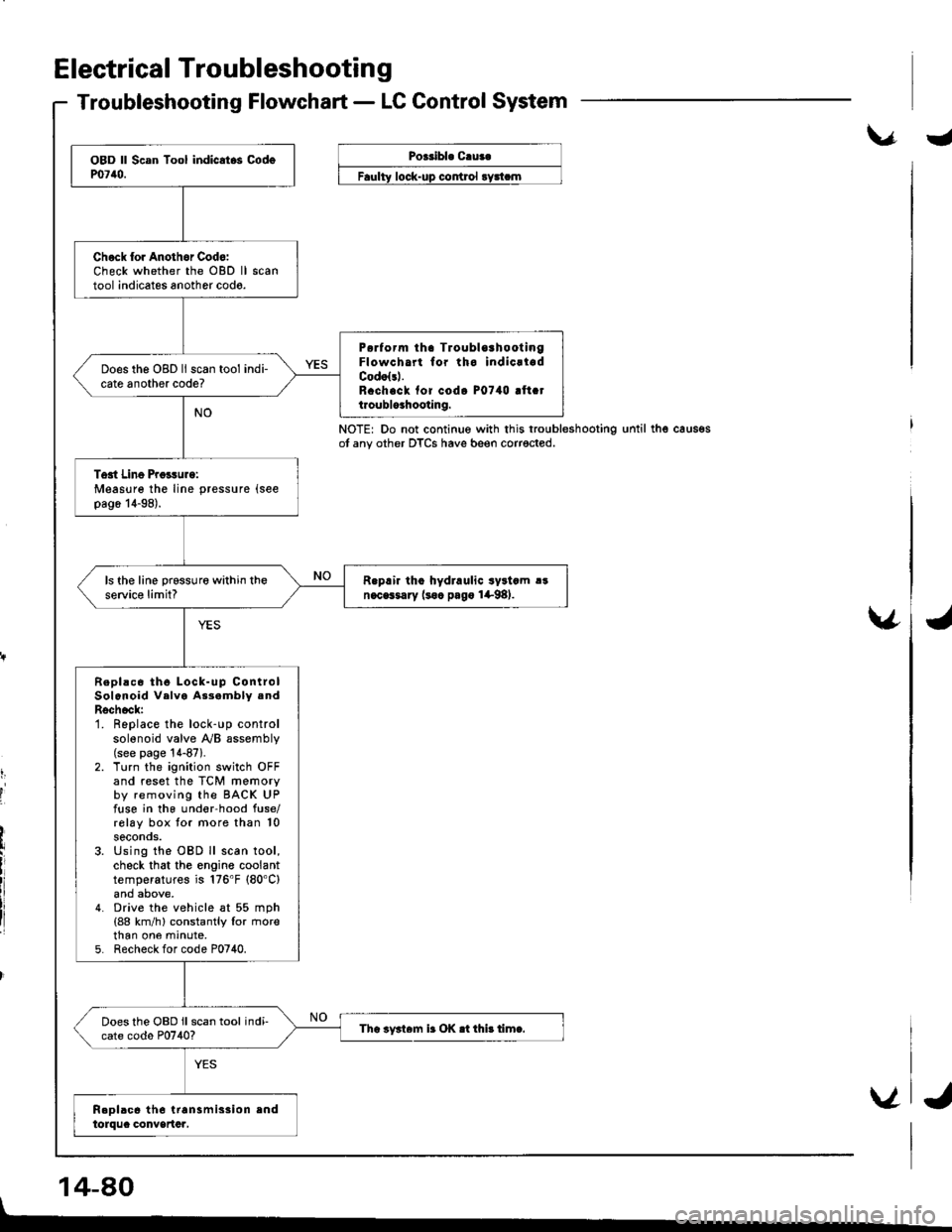
Electrical Troubleshootin g
Troubleshooting Flowchart - LC Control System
\.r.Poeribl. C.ua.
control
NOTE: Do not continue with this troubleshootingot any other DTCS have beeo corrected.until thg caus€s
v
t,
I
'I
14-80
Chock lor Anothor Cod6:Check whether the OBD lltool indicates another codo.
P6rform tha TroublorhootingFlowcha for tho indicrladCodolsl.R.ch.ck fof codo P0740 !ft.tt.oublo3hooting.
Does the OBD ll scan tool indi-cate another code?
Tost Line Proisurg:Measure the line pressure (see
pag6 14-98).
R.prir tho hydraulic syltcm !!n.cGsary (soc pago 1+98).ls the line prsssure within theservic€ limit?
Repl!c6 th6 Lock-up ControlSolenoid Velva As3ambly .ndRschock:1. Replace the lock-up controlsolenoid valve y'y'B assembly(see page '!4-87).
2. Turn the ignition switch OFFand reset the TCM memoryby removing the BACK UPfuse in the und€r-hood fuse/rolay box tor more than 10seconos.3. Using the OBD ll scan tool,check that the engine coolanttemperatures is 176'F (80'C)
4. Drive the vehicle at 55 mph(88 km/h) constantly lor rnorethan one mrnute,5. Recheck for code P0740.
Does the OBD ll scan tool indi-cate codo P0740?Tha iy3t6m ir OK .t thi! timc.
V
I
J
Page 498 of 1681
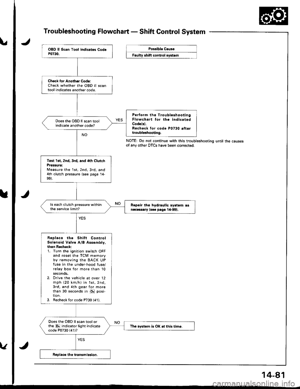
Troubleshooting Flowchart - Shaft Control System
NOTE: Do not continue with this troubleshootlng until the causesof any other DTCS have been corrected.
Chock foi Another Code:Check whether the OBD ll scantool indicates another code.
Psrtorm tho Tioubla3hootingFlowch.rt fo. th. indicatodCodcl.l.Rechsck tor code P0730 attoltroublolhooting.
Does the OBD ll scan toolindicate anothor code?
Tost 1st, 2nd, 3rd, and 4th ClutchProssuro:Measure the 1st,2nd,3rd, and4th clutch pressure (see page 14-
ls each clutch pressure withinthe service limit?R.p!ir lhG hydraulic ry3t.m ranac.3!.ry l3€e pago 1+991.
Roplace the Shilt ContiolSolonoid Valve A/B Assombly,thon Recheck:1. Turn the ignition switch OFFand reset the TCM memoryby removing the BACK UPfuse in the under-hood fuse/relay box for more than '10
seconds.2. Orive the vehicle at over 12mph (20 km/h) in lst,2nd,3rd, and 4th gear for morethan 30 seconds in E posi-tion.3, Recheck for code P730 (41).
Does the OBD llscan toolorthe E indicator light indicatecode P0730 (4'1)?Tho systom is OX etthi3 timo.
Poitible C.uBe
F""lty "hlft ".^t..t ",/"t".