HONDA INTEGRA 1998 4.G Owners Manual
Manufacturer: HONDA, Model Year: 1998, Model line: INTEGRA, Model: HONDA INTEGRA 1998 4.GPages: 1681, PDF Size: 54.22 MB
Page 91 of 1681
\
Valve Seats
Reconditioning
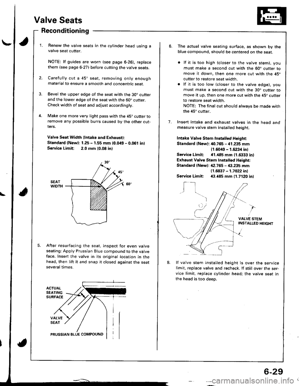
ACTUALSEATINGSURFACE
VALVESEAT
Renew the valve seats in the cylinder head using avalve seat cutter.
NOTE: lf guides are worn (see page 6-26), replace
them {see page 6-27) before cutting the valve seats.
Carefully cut a 45" seat, removing only enoughmaterial to ensure a smooth and concentric seat.
Bevel the upper edge of the seat with the 30. cutterand the lower edge of the seat with the 60. cutter.Check width of seat and adjust accordingly.
Make one more very light pass with the 45o cutter toremove any possible burrs caused by the other cut-rers.
V8lv6 S€at Width (lntake and Exhaustl:
Standard {New}: 1.25 - 1.55 mm {0.0/t{, - 0.061 in}
S€rvice Limit: 2.0 mm 10.08 in)
After resurfacing the seat, inspect for even valveseating: Apply Prussian Blue compound to the valveface. Insert the valve in its original location in thehead, then lift it and snap it closed against the seatseveral times.
PRUSSIAN BLUE COMPOUNO
6-29
o.The actual valve seating surface, as shown by theblue compound, should be centered on the seat.
lf it is too high (closer to the valve stem), you
must make a second cut with the 60" cutter tomove it down, then one more cut with the 45"
cutter to restore seat width.
lf it is too low (closer to the valve edge), you
must make a second cut with the 30. cutter tomove at up, then one more cut with the 45. cutterto restore seat width.
NOTE: The final cut should always be made with
the 45" cutter.
Insert intake and exhaust valves in the head andmeasure valve stem installed height.
Intake Valve Stem Inst8lled Height:
Standard lN6wl: 40.765 - i11.235 mm(1.6049 - 1.6234 in)
Servico Limiti i01.,|85 mm (1.6333 in)
Exhaust Valv€ Stem Installed Height:
Standard {Newl: ,[2.765 - 4:1.235 mm
1.
{1.68i}7 - 1.7022 inl,(1.485 mm 11.7120 inlService Limit:
I_1I
VALVE STEMINSTAI-LED HEIGHT
8.lf valve stem installed height is over the servicelimit, replace valve and recheck. lf still over the ser-vice limit, replace cylinder head; the valve seat in
the head is too deep.
Page 92 of 1681
Cylinder Head
Wapage
NOTE: lf camshaft-to-holder oil clearances (see page 6
22) arc nol within specification, the head cannot be
resurfaced.
lf camshaft-to-holder oil clearances are within specifica-
tions, check the head for warpage.
lf warpage is less than 0.05 mm (0.002 in) cylinder
head resurfacing is not required.
lf warpage is between 0.05 mm (0.002 in) and 0.2 mm
(0.008 in). resurface cylinder head.
Maximum resurface limit is 0.2 mm (0.008 in) based
on a height of 132.0 mm (5.20 in).
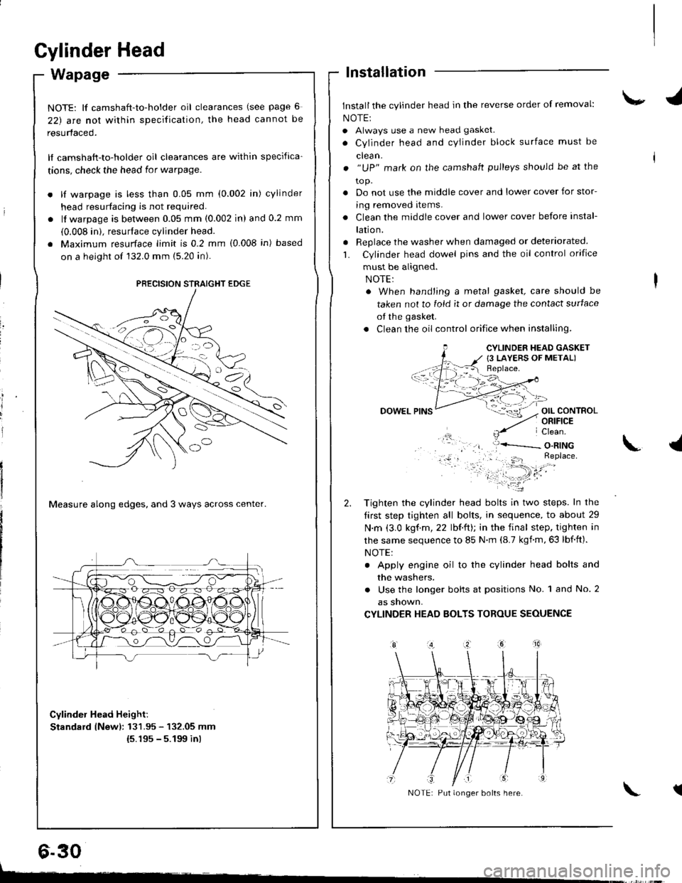
Measure along edges, and 3 ways across center.
Cylinder Head Height:
Standard lNewl: 131.95 - 132.05 mm(5.195 - 5.199 inl
lnstallation
Install the cylinder head in the reverse order of removal:
NOTE:
. Always use a new head gasket.
. Cylinder head and cYlinder block surface must be
clean.
. "UP" mark on the camshaft pulleys should be at the
to p.
. Do not use the middle cover and lower cover for stor-
ing removed items.
. Clean the middle cover and lower cover before instal-
lation.
. Replace the washer when damaged or deteriorated
L Cylinder head dowel pins and the oil control orifice
must be aligned.
. When hand'ing a metal gasket, care should be
taken not to fold it or damage the contact surface
of the gasket.
. Clean the oil control orifice when installing,
OIL CONTROLORIFICE
PRECISION STRAIGHT EDGE
6.30
CYLINDER HEAD GASKET
{3 LAYERS OF METAL)
DOWEL
Tighten the cylinder head bolts in two steps. In the
tirst step tighten all bolts, in sequence, to about 29
N.m (3.0 kgf.m,22 lbf.ft); in the final step. tighten in
lhe same sequence to 85 N.m (8.7 kgnm,63 lbf.ft).
NOTE:
. Apply engine oil to the cylinder head bolts and
the washers.
. Use the longer bolts at positions No. 1 and No. 2
as snown,
CYLINDER HEAD BOLTS TOROUE SEOUENCE
\.l
tNOTE: Put longer bolts here.
t-
Page 93 of 1681
\-
L
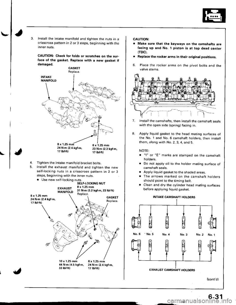
Install the intake manifold and tighten the nuts in acflsscross pattern in 2 or 3 steps. beginning with theinner nuts.
CAUTION: Check lor folds or scratches on the sur-face ol the gasket. Replace with a new gasket ildamaged.GASKETReplace.
INTAKEMANIFOLD
4. Tighten the intake manifold bracket bolts.5. Install the exhaust maniiold and tighten the newself-locking nuts in a crisscross pattern in 2 or 3steps, beginning with the inner nuts.. Use new self-locking nuts.
EXHAUSTMANIFOLD
GASKETReplace.
4
10 x 1.25 mm 8 x 1.25 mm4,{ N.rn 14.5 kgf.m, 24 N.m {2.4 kgtm,33 tbf.ftl '17 tbf.ft)
SELF.LOCKING NUT8 x 1.25 mm31 N.m (3.2 kgt m,23 lbf.ft)Replace.1 .25 mmN.m {2.4 kg{.m,rbrftt
\q
8x2417
",', r, ^-'-"-!,1,,,';-21N.m l2.1kglm, 23 N.m (2.3 ksf.m,17lbf.ftl 17 tbf.ftr
6-31
CAUTION:
. Make sure that the keyways on the camshafts aretacing up and No. 1 piston is at top dead cenier
tTDCt.. Replacethe rocker arms in their original positions.
6. Place the rocker arms on the pivot bolts and thevalve stems.
7.
8.
Install the camshafts, then install the camshaft sealswith the open side (spring) facing in.
Apply liquid gasket to the head mating surfaces otthe No. 1 and No. 6 camshaft holders, then installthem, along with No.2,3, 4, and 5.
NOTE:
. "l" or "E' marks are stamped on the camshaftholders.
. Do not apply oil to the holder mating surface ofcamshaft seals.. Apply liquid gasket to the shaded areas.. The arrows marked on the camshaft holdersshould point to the timing belt.. Clean and dry the cylinder head mating surfacesbefore applying liquid gasket.
INTAKE CAMSHAFT HOLDERS
No.6 No.5No.4No.3 No.2 No. 1
{cont'd)
Page 94 of 1681
Cylinder Head
Installation (cont'dl
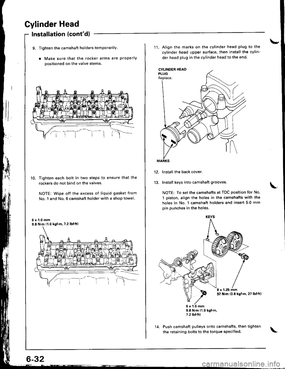
9, Tighten the camshaft holders temporarily.
a Make sure that the rocker arms are properly
positioned on the valve stems
10. Tighten each bolt in two steps to ensure that the
rockers do not bind on the valves.
NOTE: wipe off the excess of liquid gasket from
No. 1 and No. 6 camshaft holder with a shop towel
6x1.0mm9,8 N.m 11.0 kgf m, 7.2 lbt'ftl
\-
11. Align the marks on the cylinder head plug to the
cylinder head upper surface, then install the cylin-
der head plug in the cylinder head to the end.
CYLINDEB HEADPLUGReplace.
13.
lnstall the back cover.
Install keys into camshaft grooves.
NOTE: To set the camshafts at TDC position for No.
1 piston, align the holes in the camshafts with the
holes in No. 1 camshsft holders snd insert 5.0 mm
pin punches in the holes.
8 x 1.25 mmt7 N.|rl {3.8 kst.m,27 lbf.ftl
6x1.0mm9.8 N.m {1.0 kgt m.7.2 tbr.ft)
Push camshaft pulleys onto camshafts, then tighten
the retaining bolts to the torque specified.
KEYS
14.
Page 95 of 1681
15.
16.
17.
Install the timing belt (see page 6-12).
Adjust the valve clearance (see page 6-3).
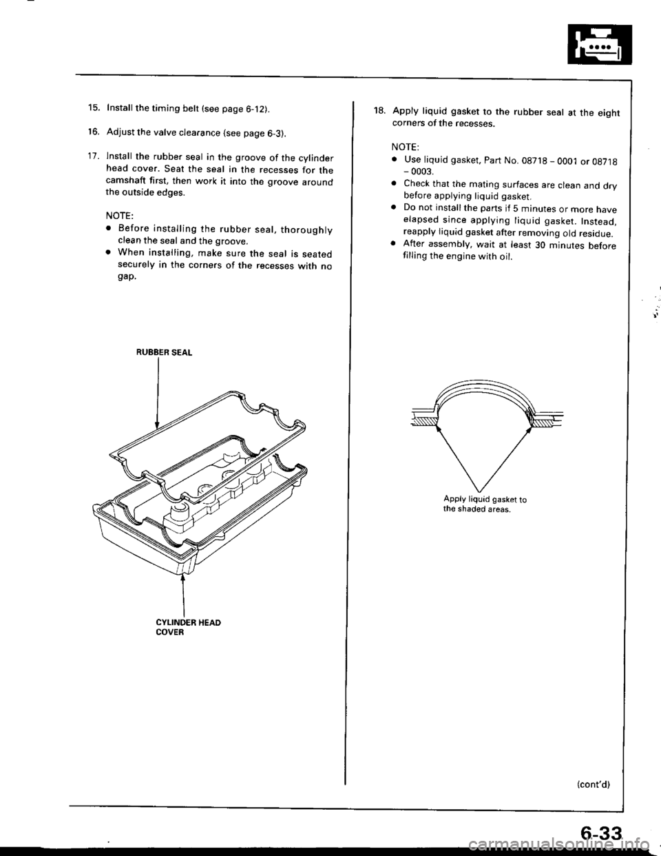
lnstall the rubber seal in the groove of the cylinderhead cover. Seat the seal in the recesses for thecamshaft first, then work it into the groove aroundthe outside edges.
NOTE:
. Before installing the rubber seal, thoroughlyclean the seal and the groove.
. When installing, make sure the seal is seatedsecurely in the corners of the recesses with nogap.
RUEBER SEAL
18.Apply liquid gasket to the rubber seal at the eightcorners of the recesses.
NOTE:
. Use liquid gasket, Part No. 08718 - OO01 or 08718- 0003.
. Check that the mating surfaces are clean and drybefore applying liquid gasket.. Do not installthe parts if 5 minutes or more naveelapsed since applying liquid gasket. Instead,reapply liquid gasket after removing old residue.. After assembly, wait at least 30 minutes beforefilling the engine with oil.
Apply liquid gasket tothe shaded areas.
(cont'd)
6-33
Page 96 of 1681
Cylinder Head
Installation (cont'dl
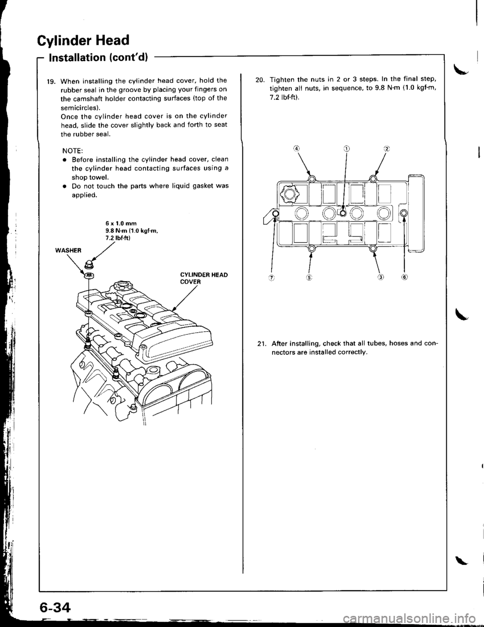
19. When installing the cylinder head cover. hold the
rubber seal in the groove by placing your fingers on
the camshaft holder contacting surfaces (top of the
semicircles).
Once the cylinder head cover is on the cylinder
head, slide the cover slightly back and iorth to seat
the rubber seal.
NOTE:
. Before installing the cylinder head cover, clean
the cylinder head contacting surfaces using a
shop towel.
. Do not touch the parts where liquid gasket was
applied.
6x1.0mm9.8 N.m {1.0 kgf.m,7 .2 tblltl
6-34
\
21.
Tighten the nuts in 2 or 3 steps. In the final step,
tighten ali nuts, in sequence, to 9.8 N'm (1.0 kgim,
7.2 tbf.ft).
After installing, check that all tubes, hoses and con-
nectors are installed correctly.
Page 97 of 1681

Page 98 of 1681

Page 99 of 1681

Page 100 of 1681
