HONDA INTEGRA 1998 4.G Repair Manual
INTEGRA 1998 4.G
HONDA
HONDA
https://www.carmanualsonline.info/img/13/6069/w960_6069-0.png
HONDA INTEGRA 1998 4.G Repair Manual
Trending: tire type, air condition, manual radio set, fuel additives, fuel tank capacity, load capacity, headlight aiming
Page 61 of 1681
Page 62 of 1681
I
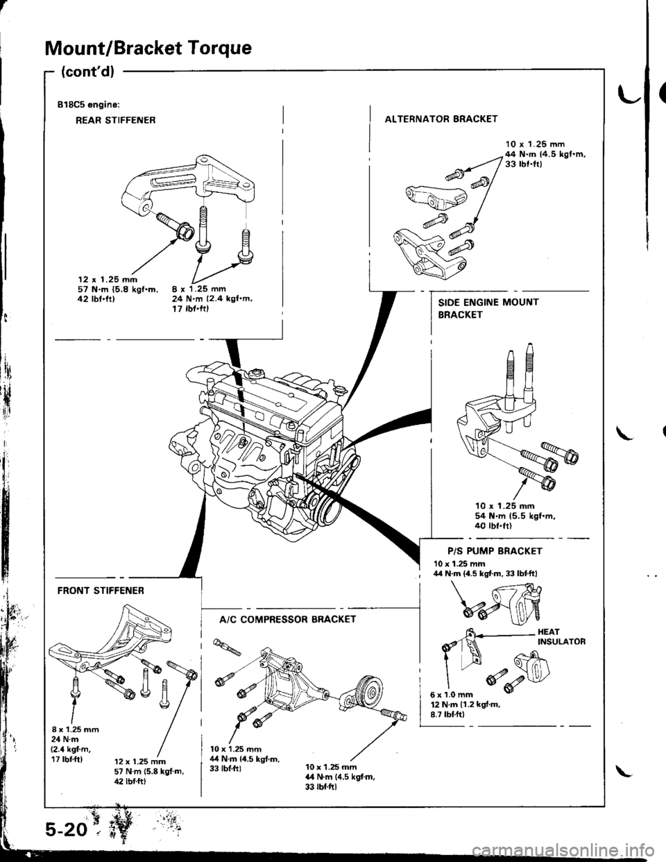
Mount/Bracket Torque
(cont'dl
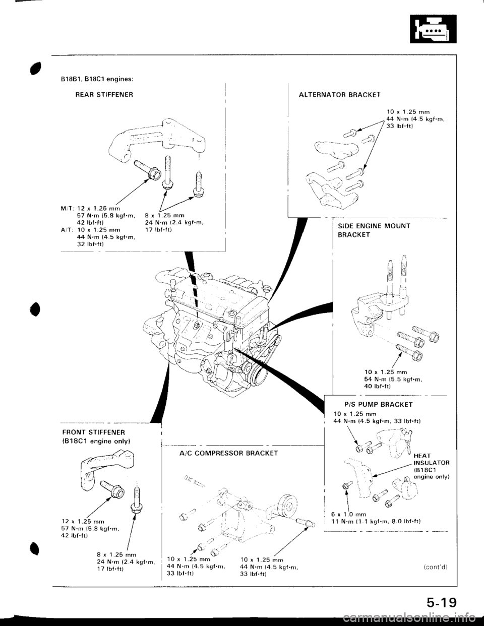
818C5 engine:
REAR STIFFENER
(
ALTERNATOR BRACKET
10 r 1.25 mm
12 x 1.25 mm57 N.m {5.8 kgf.m,42 tbt'trt24 N.m 12.4 kgl.m,17 rbf'ftt
--q;;/44N'mtr.5kst'm'v=ahp /
w#
q7
10 x 1.25 mm54 N.m 15.5 kgf.m.40 rbt.frl
P/S PUMP BRACKET
10 x 1.25 mm
t:
ltri
rH
{ir
I\
; /r/r N.m {4.5 kgf.m, 33 lbtftl
FRONT STIFFENER
A/C COMPRESSOR BRACKET
I x'1.25 mm24 N.m(2.4 kgf'm,17 rbf.ft)12 x 1.25 mm57 N.m 15.8 kgt.m,42 lbf.ftt
6\--- HEAr
d'1N ^rNsuLAroR
I --H Gh\
"
*o-r$l/
sxrlomm v
12 N.m 11.2 kgf.m.8.7 tbf.ftt
Page 63 of 1681
Page 64 of 1681
Page 65 of 1681
r.lJ
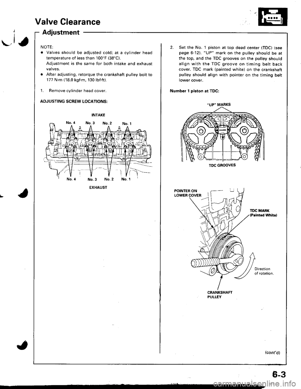
Valve Clearance
Adjustment
NOTE:
. Valves should be adjusted cold; at a cylinder head
temperature of less than 100'F (38"C).
Adjustment is the same for both intake and exhaust
valves.
. After adjusting, retorque the crankshaft pulley bolt to
177 N.m (18.0 kgf.m, 130 lbf'ft).
1. Remove cylinder head cover.
ADJUSTING SCREW LOCATIONS:
EXHAUST
(
"UP" MARKS
TDC GBOOVES
2. Set the No. 1 piston at top dead center (TDC) (see
page 6-12). "UP" mark on the pulley should be at
the top, and the TDC grooves on the pulley should
align with the TDC groove on timing belt back
cover. TDC mark (painted white) on the crankshaftpulley should align with pointer on the timing belt
lower cover.
Number 1 piston at TDC:
POINTER ONLOWER
TDC MAFK(P.inted whh.l
(cont'd)
6-3
Page 66 of 1681
Valve Clearance
Adjustment (cont'dl
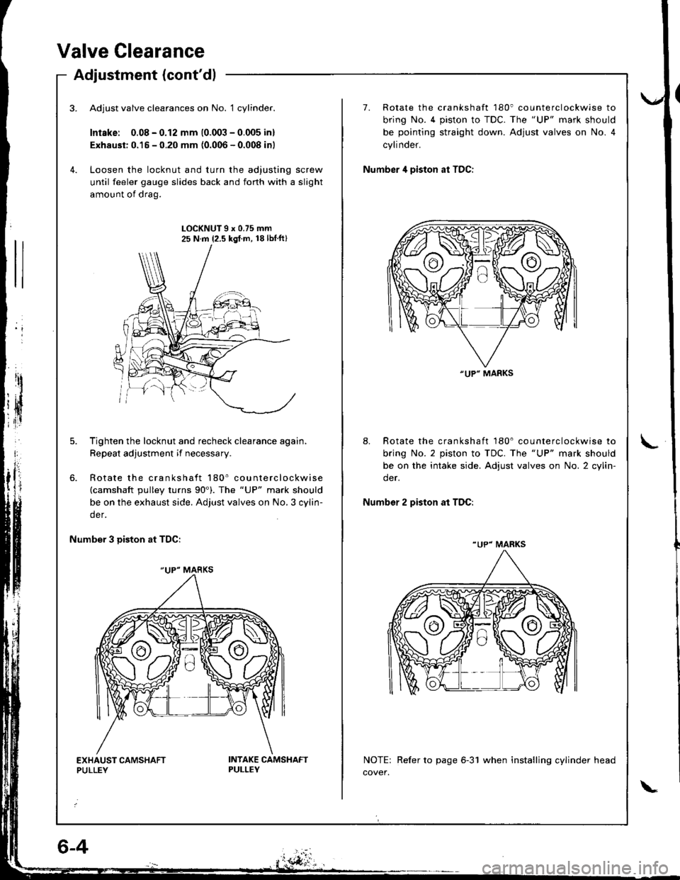
Adjust valve clearances on No. 1 cylinder.
Intske: 0.08 - 0.12 mm (0.003 - 0.005 inl
Exhaust: 0.15 - 0.20 mm (0.006 - 0.008 inl
Loosen the locknut and turn the adjusting screw
until feeler gauge slides back and forth with a slight
amount of drag.
7. Rotate the crankshaft 180' counterclockwise to
bring No. 4 piston to TDC. The "UP" mark should
be pointing straight down. Adjust valves on No. 4
cylinder.
Number 4 piston at TDC:
LOCKNUT9x0.75mm25 N.m {2.5 kgl.m, 18lbtft}
Tighten the locknut and recheck clearance again,
Repeat adjustment if necessary.
Rotate the crankshaft 180' counterclockwise(camshaft pulley turns 90'). The "UP" mark should
be on the exhaust side. Adjust valves on No,3 cylin-
der.
8. Rotate the crankshaft 180' counterclockwise to
bring No. 2 piston to TDC. The "UP" mark should
be on the intake side. Adjust valves on No. 2 cylin-
der.
Number 2 piston at TDC:
Number 3 Diston at TDC:
NOTE: Refer to page 6-31 when installing cylinder head
cover.
"UP" MARKS
"UP" MARKS
"UP" MARKS
Page 67 of 1681
Valve Seals
Replacement (cylinder head removal not required)
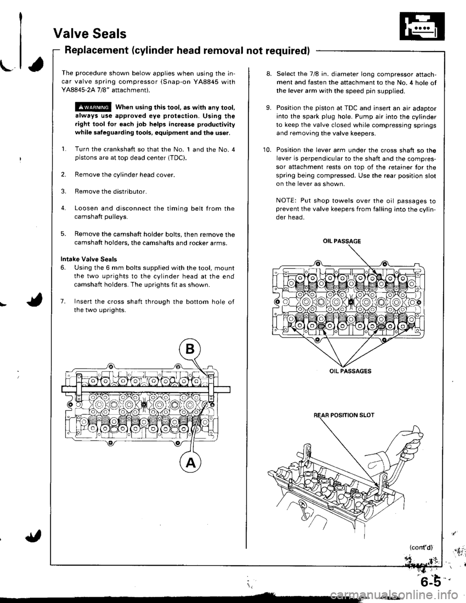
The procedure shown below applies when using the in-
car valve spring compressor (Snap-on YA8845 with
Y AAA45-2A 1 /8" attachment).
!@@ When using this tool, as with any tool,
always use approved eye protection. Using the
fight tool tor each job helps increase productivity
while safeguarding tools, equipment and ihe user.
Turn the crankshaft so that the No. 1 and the No. 4pistons are at top dead center (TDC).
Remove the cylinder head cover.
Remove the distributor.
Loosen and disconnect the timinq belt from the
camshaft oullevs.
5. Remove the camshaft holder bolts, then remove the
camshaft holders, the camshafts and rocker arms.
Intake Valve Seals
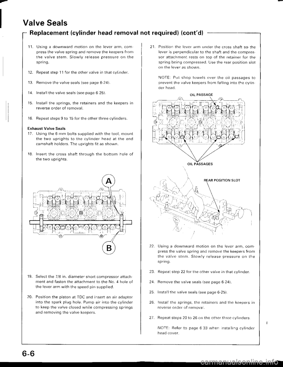
6. Using the 6 mm bolts supplied with the tool, mount
the two uprights to the cylinder head at the end
camshaft holders. The uprights fit as shown.
7. Insert the cross shaft through the bottom hole of
the two uprights.
8.
9.
10.
Select the 7/8 in. diameter long compressor attach-
ment and fasten the attachment to the No. 4 hole of
the lever arm with the speed pin supplied.
Position the piston at TDC and insen an air adaptor
into the spark plug hole. Pump air into the cylinder
to keep the valve closed while compressing springs
and removing the valve keepers.
Position the lever arm under the cross shaft so the
lever is perpendicular to the shaft and the compres-
sor attachment rests on top of the retainer for the
spring being compressed. Use the rear position slot
on the lever as shown.
NOTE: Put shop towels over the oil passages toprevent the valve keepers from falling into the cylin-
der head.
OIL PASSAGE
OIL PASSAGES
(cont'd),'.itil
i,
'6-b-'
Page 68 of 1681
Page 69 of 1681
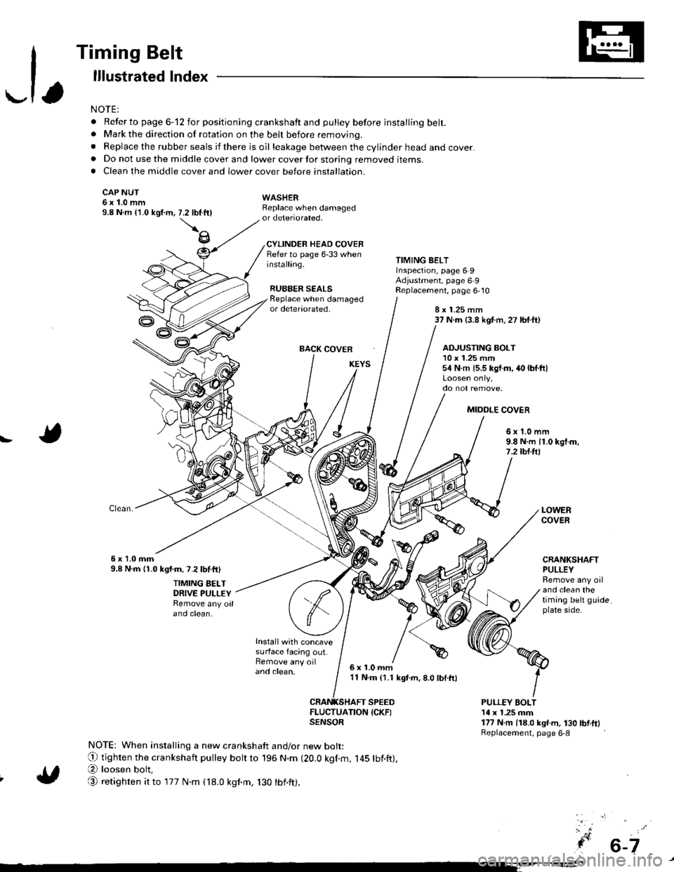
-1,
Timing Belt
lllustrated lndex
NOTE:
. Refer to page 6-12 for positioning crankshaft and pulley before installing belt.. Mark the direction of rotation on the beh before removing.
. Replace the rubber seals if there is oil leakage between the cylinder head and cover.. Do not use the middle cover and lower cover for storing removed items.. Clean the middle cover and lower cover before installation.
CAP NUT6x1.0mm9.8 N.m {'1.0 kgi.m,
WASHERReplace when damagedor deteriorated.
CYLINDER HEAD COVERRefer to page 6-33 wheninstalling.
RUBBER SEALS
7.2 tbftll
TIMING BELTInspection, page 6 9Adjustment, page 6 9Replacement, page 6,10Beplace when damagedor deteriorated,8 x 1.25 mm37 N.m (3.8 kgf.m, 27 lbf.ft)
BACK COVER
Install with concavesurface facing out.Remove any oiland clean,
ADJUSTING BOLT10 x 1.25 mm54 N.m {5.5 kgt.m, 40 lbf.ltl
MIDDLE COV€R
!6x1.0mm9.8 N.m {1.0 kgf.m,7.2lbl.ftl
6x 1.0mm9.8 N.m 11.0 kgl.m, 7.2lbf.ftl
TIMING BELTDRIVE PULLEYRemove any oilano ctean.
LOWERCOVER
CRANKSHAFTPULLEYRemove any oiland clean thetiming belt guideplate side.
6x1.0mm'11 N.m (1.1 kgf.m, 8.0 lbI.ft)
SPEED
ItEi:lufrroN {cKF)
NOTE: When installing a new crankshaft and/or new bolt:
O tighten the crankshaft pulley bott to 196 N.m (20.0 kgf.m, 145 tbf.ft),
@ loosen bolt,
@ retighten it to 177 N.m (18.0 kgnm, 130 tbnft).
PULLEY EOLT14 x 1.25 mm177 N.m (18.0 kgf.m, 130 bnftlReplacement, page 6-8
6-7
Page 70 of 1681
Grankshaft Pulley Bolt
Replacement
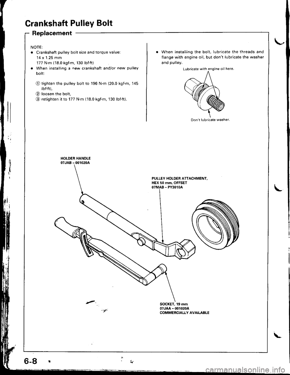
NOTE:
o Crankshaft pulley bolt size and torque value:'14 x 1.25 mm
177 N.m (18.0 kgf m, 130 lbtft)
a When installing a new crankshaft and/or new pulley
bolt:
O tighten the pulley bolt to 196 N.m (20.0 kgim, 145
lbf.ft),
@ loosen the bolt,
o retighten it to 177 N.m (18.0 kgf.m, 130 lbift).
When installing the bolt, lubricate the threads and
flange with engine oil, but don't lubricate the washer
and DUllev.
Don't lubricate washer.
PULLEY HOLDEB ATTACHMENI,HEX 50 mm, OFFSETOTMAB - PY3O1OA
SOCKET, 19 mm07JAA - @1020ACOMMERCIALLY AVAILABLE
\-
Trending: warranty, lock, check transmission fluid, hood open, C506, warning, fuse box diagram
