Cylinder HONDA INTEGRA 1998 4.G Workshop Manual
[x] Cancel search | Manufacturer: HONDA, Model Year: 1998, Model line: INTEGRA, Model: HONDA INTEGRA 1998 4.GPages: 1681, PDF Size: 54.22 MB
Page 1122 of 1681
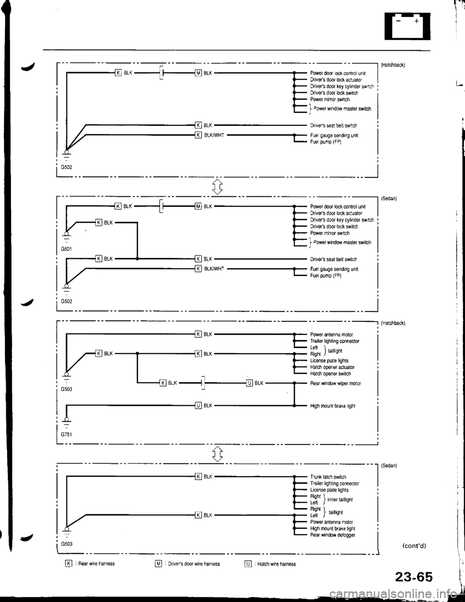
I "tl
III
J- - - - --------- l (Haldlback)
Power door oci contro unrt IDriveas door lockaclualof I;Dtlver's door key cylinder swrtclrDfveas door lock swilch
BLKMHT ---1-
I Power window masler swildl)
Dr veis seal belt swilch
Fue gauge sending lnilFue plmp (FP)
ri:
----------l (sedan)
Power dooa lock conlrol unil IDriveas door lock aclualor I
BLKWHT-
Drlver's door key cylinder swllchDrlve/s door lock swilch
I Power window masler swilch)
Dive. s seal beit swilch
Foelgaee sending unitFuelpump (FP)
i Gso2
_ _ _--_______.] {Halchback)
r- || | F T6iler tiqhxng conneclor I
lil i ,",rror,'nqfi JLicense plale lighlsHalci opener aotualorHalci opener swilch
Rear window wiper molor
High mounl hake ighl
otw ^ -n1
t-
l_:1' ^r;-"-1 7_1;.^G503
Trunk lalch swildlTf ailer light ng conneclorLicense plate lighlsRiohl I�L; J Inner larqnr
Riohl I� .Le-ft J raflqnl
High mounl brake lighlRea. window d€logger
I
""*'�
I
(cont'd)
B : R6arwire hamessM : Dver's doorwire harness@ Hatchwire harness
:
G503
23-65
Page 1155 of 1681
lgnition System
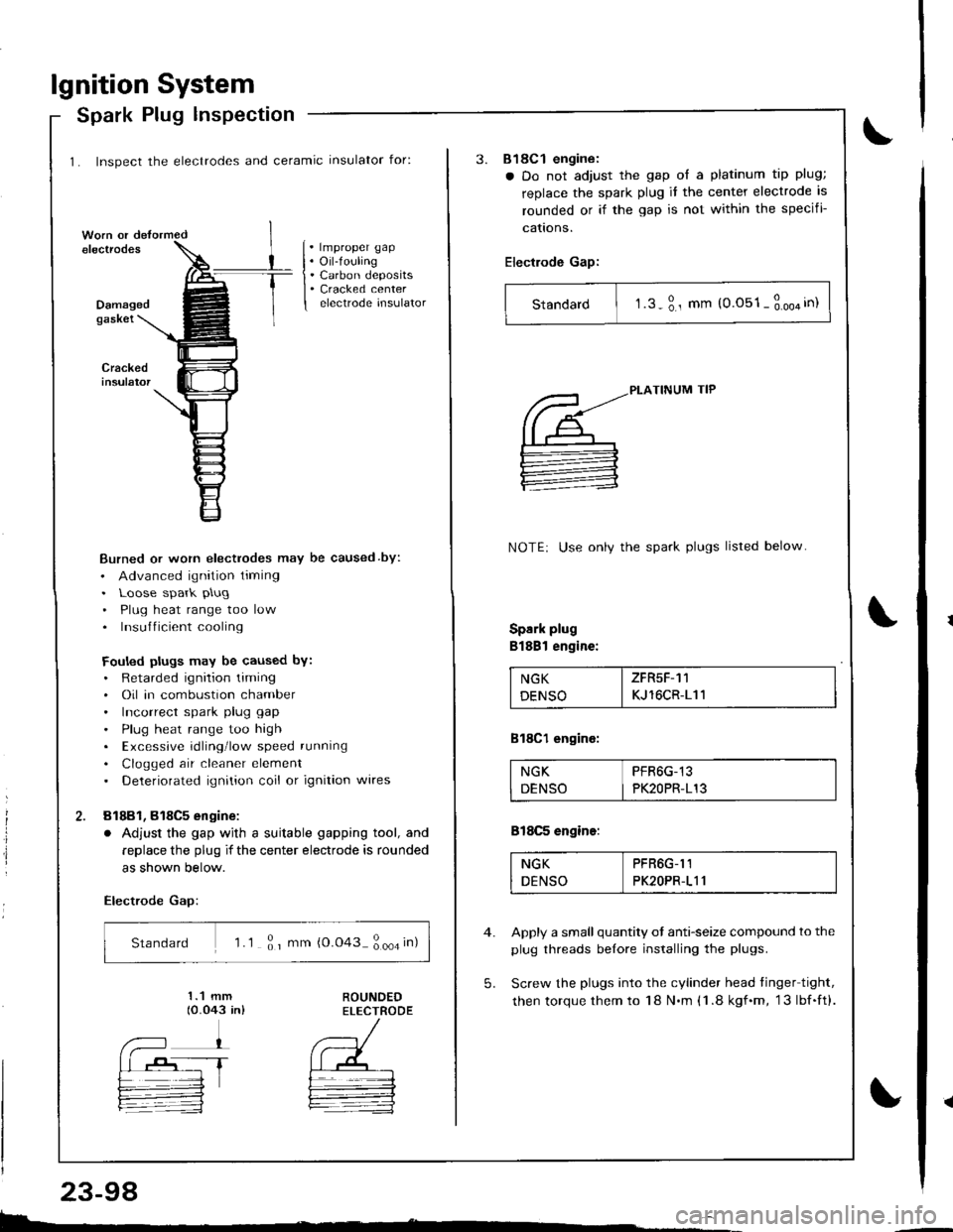
1. Inspect the electrodes and ceramic insulator for:
Spark Plug lnspection
. lmproper gap. Oil-fouling. Carbon deposits. Cracked centerelectrode insulatorDamagedgaskei
Burned or worn electrodes may be caused by:
. Advanced ignition timing. Loose spark plug
. Plug heat range too low. Insufficient cooling
Fouled plugs may be caused bY:. Retarded ignition liming. Oil in combustion chamber. Incorrect spark plug gap
. Plug heat range too high. Excessive rdling'low speed running
. Clogged air cleaner element. Deteriorated ignition coil or ignition wires
81881, 818C5 engine:
. Adjust the gap wjth a suitable gapping tool, and
replace the plug if the center electrode is rounded
as shown below.
Electrode Gap:
Standard 'l .1 ; r mm {0.043 ; ooa in)
E.
23-98
3.818C1 engine:
a Do not adjust the gap ol a platinum tip plug;
replace the spark plug it the center electrode is
rounded or if the gap is not within the specifi-
cattons.
Electrode Gap:
Standard I t.s-3., mm (0.051-3.oo4in)
5.
PLATINUM TIP
NOTE: Use onlv the spark plugs listed below
Spark plug
Bl88l engine:
NGK I ZFR5F-11
DENSO I KJ 16CR-111
818C1 engine:
NGK PFR6G-13
DENSO I PK2OPR-113
818C5 engine:
NGK PFR6G-I1
DENSO PK2OPR-111
Apply a small quantity ot anti-seize compound to the
plug threads belore installing the plugs.
Screw the plugs into the cylinder head tinger tight,
then torque them to 18 N.m (1 .8 kgf.m, 13lbf.ft).
Page 1203 of 1681
Interlock System
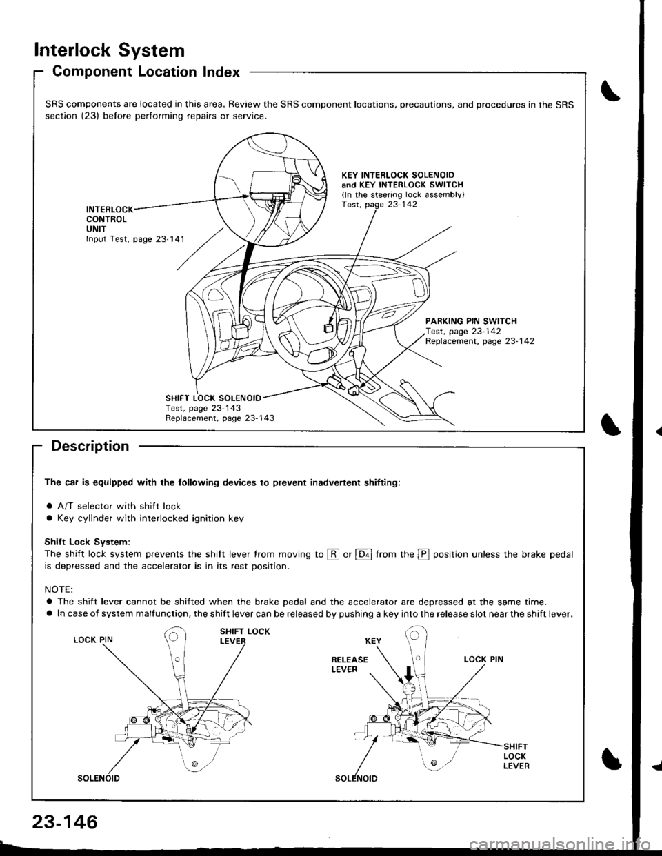
Component Location Index
Description
The car is equipped with the lollowing devices to plevent inadvertent shifiing:
a A/T selector with shift lock
a Key cylinder with interlocked ignition key
Shift Lock Svstem:
The shift lock system prevents the shilt lever trom moving to @ or [6ol from the p position unless the brake pedal
is depressed and the accelerator is in its rest position.
NOTE:
a The shift lever cannot be shifted when the brake pedal and the accelerator are depressed at the same time.
a In case of system malfunction, the shift lever can be released by pushing a key into the release slot near the shift lever.
SRS components are located in this area. Review the SRS component locations, precautions, and procedures in the SRS
section (23) belore performing repairs or service.
KEY INTERLOCK SOLENOIDand KEY INTERLOCK swlTCH
{ln the steering lock assembly}
INTERLOCKCONTROLUNIT
PARKING PIN SWITCHTest, page 23-142Replacement, page 23-1 42
Replacement, page 23-143
SHIFT LOCK SOL€NOIDTest, page 23 143
23-146
Page 1204 of 1681
)
t
t
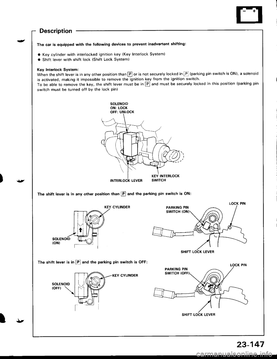
Description
Ths cal is equipped with the tottowing devices to prevent inadvertenl shifting:
a Key cylinder with interlocked ignition key (Key Interlock System)
a shift lever with shift lock (shilt Lock system)
Key Interlock System:
When the shift lever is in any other position than @ or is not securely locked in @ (parking pin switch is ON), a solenoid
is activated, making it impossible to remove the ignition key from the ignition switch.
To be able to remove the key, the shift lever must be in E] and must be securely locked in this position {parking pin
switch must be turned oft by the lock pin)
The shift lever is in any othel position than El and the psrking pin switch is ON:
CYLINDER
The shitt lever is in l!] and the parking pin switch is OFF:
KEY CYLINOER
PARKING PIN
SHIFT LOCK LEVER
SHIFT LOCK LEVER
{t
23-147
Page 1296 of 1681
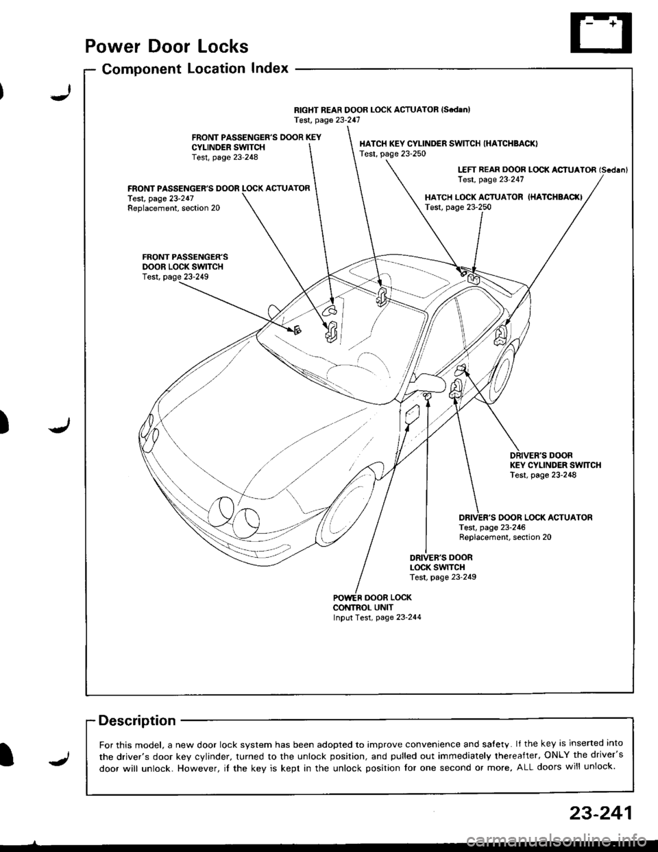
Power Door Locks
Component LocationIndex
RIGHT REAR DOOR LOCK ACTUATOR {SedanlTest, page 23-247
FRONT PASSENGER'S DOOR KEYCYI-INDER SWITCHTest, page 23-248
HATCH KEY CYLINDER SWITCH (HATCHBACK)
Test, page 23-250
LEFT REAR DOOR LOCK ACIUATOR (Scdlnl
Test, page 23'247FRONT PASSENGER'S DOOR LOCK ACTUATORlest, page 23-247Replacement, soction 20HATCH L(rcK ACTUATOR IHATCHBAC(ITest, page 23-250
FRONT PASSENGER'SDOOR LOCK SWITCHTest, page 23-249
DRIVER'S DOORKEY CYLINDER SW]TCHTest, page 23-248
OOOR LOCK ACTUATORTest, page 23-246Replacement, section 20
DRIVEB'S DOORLOCK SWITCHTest, page 23-249
oooR LocKCONTNOL UNITInput Test, page 23-244
-)
J)
I
For this model, a new door lock svstem has been adooted to imDrove convenience and salety. lf the key is inserted into
the driver's door kev cvlinder. turned to the unlock position, and pulled out immediately thereafter, ONLY the driver's
door will unlock. However, il the key is kept in the unlock position for one second or more, ALL doors will unlock.J
23-241
Page 1297 of 1681
![HONDA INTEGRA 1998 4.G Workshop Manual Power Door Locks
Circuit Diagram
@*"
DR]VERS000R LocKSWITCH
NATCN KEYCYLINDER SWITCH
L_____
ooon rocx xroe If7 l
VIKEY
DRIVERSDOOR LOCKACTUATOR
E
UNDER.HOOO FUSEi RELAY BOX
N0.41 (1004) No.s4 (40A)
HONDA INTEGRA 1998 4.G Workshop Manual Power Door Locks
Circuit Diagram
@*"
DR]VERS000R LocKSWITCH
NATCN KEYCYLINDER SWITCH
L_____
ooon rocx xroe If7 l
VIKEY
DRIVERSDOOR LOCKACTUATOR
E
UNDER.HOOO FUSEi RELAY BOX
N0.41 (1004) No.s4 (40A)](/img/13/6069/w960_6069-1296.png)
Power Door Locks
Circuit Diagram
@*"
DR]VER'S000R LocKSWITCH
NATCN KEYCYLINDER SWITCH
L_____
ooon rocx xroe If7 l
VIKEY
DRIVER'SDOOR LOCKACTUATOR
E
UNDER.HOOO FUSEi RELAY BOX
N0.41 (1004) No.s4 (40A)
DFIVERS DOORKEY CYLJNOERSWITCH
WHT/GRN
FRONTPASSENGERSDOOR LOCKACTUATOR
T--=-l-4{il^
* LEFT REARDOOR LOCKACTUATOR
,@-
* RIGHT NEARDOOR LOCKACTUATOH
-4{.ill^
HATCH LOCKACTUATOR
T-:-lfl.|.{-
LTGRN
LT BLU
A
t--lt=JKEY
i
Atl
T-tl-lKEYBLK
I
G503
.LK BLKll
tlAA
:-l
G501 G2r.G502 ercl
BLK
,l'
G5o1G502
LOCK
o
POWER DOORLOCK CONTROLUNIT
8LK
A-l
G501G502
23-242
Page 1298 of 1681
I,t
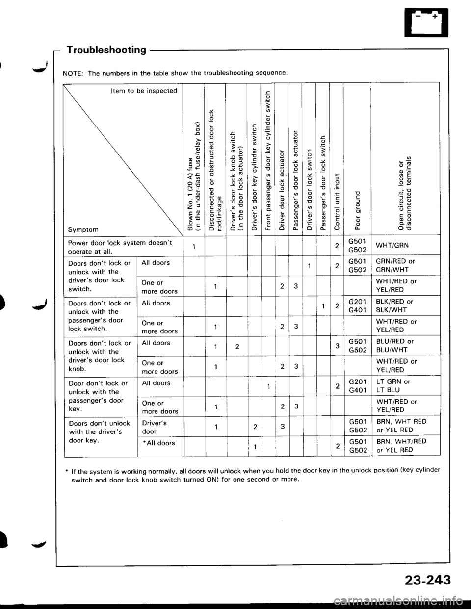
Troubleshooting
* lf the system is working normally, all doors will unlock when you hold the door key in the unlock oosrtion {key cylinder
switch and door lock knob switch turned ON) for one second or more
)
NOTE: The numbers in the table show the troubleshooting sequence
Item to be inspected
Symptom
g
;i
:
5
{,!
(,o
o-c
E5
B
'io
B
o)c
c
o
:
D
.uo
I
o)
o-
-c
:o
o
I
!
o)
cJ
o
c
c
o)
Power door lock system doesn't
operate at all.
G501
G502WHT/GRN
Doors don't lock or
unlock with the
driver's door lock
switch.
All doors2G 501
G502
GRN/RED or
GRN/WHT
One or
more doors
'I23WHT/RED or
YEL/RED
Doors don't lock or
unlock with the
passenger's door
lock switch.
All doors1G201
G401
BLK/RED or
BLK/WHT
One or
more ooors123WHT/RED or
YEL/RED
Doors don't lock or
unlock with the
driver's door lock
knob.
All doors123G501
G502
BLU/RED or
BLU/WHT
One or
more doors123WHT/RED or
YEL/RED
Door don't lock or
unlock with the
passenger's door
key.
All doorsl2G201
G401
LT GRN or
LT BLU
One or
more doors2WHT/RED or
YEL/RED
Doors don't unlock
with the driver's
door key.
Driver's
ooor23G501
G502
BRN, WHT REO
or YEL RED
*All doors1G 501
G502
BRN, WHT/RED
or YEL RED
-
23-243
Page 1300 of 1681
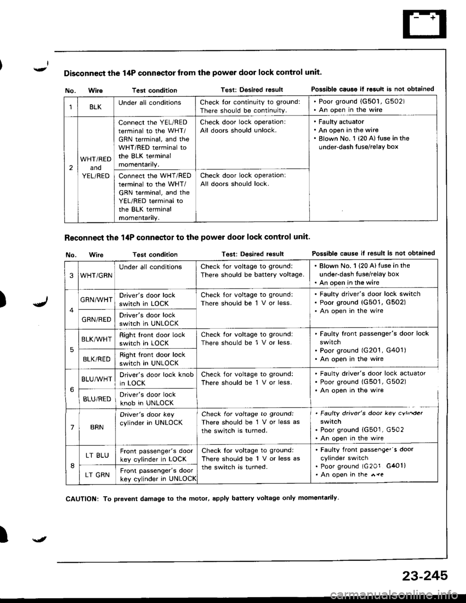
Disconnect the 14P connector from the power door lock control unit'
)
No. WileTest conditionTest: Dgsired resultPossible causo if rosult is not obtained
Reconnect the 14P conneetor to the power door lock control unit'
No. wireTest conditionTest: Desired resultPossible cause il result is not obtained
I
1BLKUnder all conditionsCheck tor continuity to ground:
There should be continuity.
. Poor ground (G50'1, G502). An open in the wire
2
WHTi RED
ano
YEL/RED
connect the YEL/RED
terminal to the WHT/
GBN terminal, and the
WHT/RED terminal to
the BLK terminal
momentarily.
Check door lock operation:
All doors should unlock.
Faulty actuator
An open in the wire
Blown No. 1 {20 A} fuse in the
under-dash Juse/relay box
Connect the WHT/RED
terminal to the WHT/
GRN terminal, and the
YEL/RED terminal to
the BLK terminal
momentanly.
Check door lock operation:
All doors should lock.
3WHT/GRN
Under all conditionsCheck for voltage to ground:
There should be battery voltage.
. Blown No. 1 (20 A) fuse in the
under-dash fuse/relay box. An open in the wire
GRN/WHTDriver's door lock
switch in LOCK
Check lor voltage to ground:
There should be 1 V or less.
Faulty driver's door lock switch
Poor ground (G501, G502)
An open in the wire
GRN/REDDriver's door lock
switch in UNLOCK
5
BLK/WHTRight front door lock
switch in LOCK
Check for voltage to ground:
There should be 1 V or less.
Faulty front passenger's door lock
switch
Poor ground (G201 , G401)
An open in the wireBLKi REDRight front door lock
switch in UNLOCK
BLU/WHTDriver's door lock knob
in LOCK
Check for voltage to ground:
There should be 1 V or less.
. Faulty driver's door lock actuator. Poor ground (G501, G502). An open in the wire
BLU/REDDriver's door lock
knob in UNLOCK
7BRN
Oriver's doo. key
cylinder in UNLOCK
Check for voltage to ground:
There should be 1 V or less as
the switch is turned.
. Faulty driver's door key cvtrrder
switch. Poor ground (G501, G502. An open in the wire
8
LT BLUFront passenger's door
key cylinder in LOCK
Check for voltage to ground:
There should be 1 V or less as
the switch is turned.
. Faulty front passengef's door
cylinder switch. poor ground lG20r G4Ol). An open in the *reLT GRNFront passenger's door
key cylinder in UNLOCK
\J
CAUTION: To prevent damage to the motol, apply battery voltage only momentarily
23-245
Page 1303 of 1681
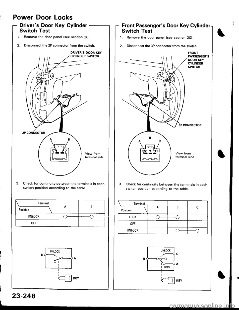
Power Door Locks
Driver's Door Key Cylinder
Switch Test
1. Remove the door panel (see section 20).
2. Disconnect the 2P connector f.om the switch.
terminal side
Check tor continuity between the terminals in eachswitch position according to the table.
Front Passenger's Door Key Cylinder
Switch Test
1. Remove the door panel (see section 20).
2. Disconnect the 3P connector from the switch.
FRONTPASSENGER'SDOOR KEYCYLINDERSwlTCH
CONNECTOR
3. Check for continuity between the terminals in eachswitch position according to the table.
Terminal
il;------__\tt
UNLOCKoo
OFF
Terminal
P**--__\c
LOCKo--o
UNLOCKoo
UNTOCK<
I
UNLOCK
r--O\:
I LOCK
23-248
(--l__!J KEYtil
Page 1305 of 1681
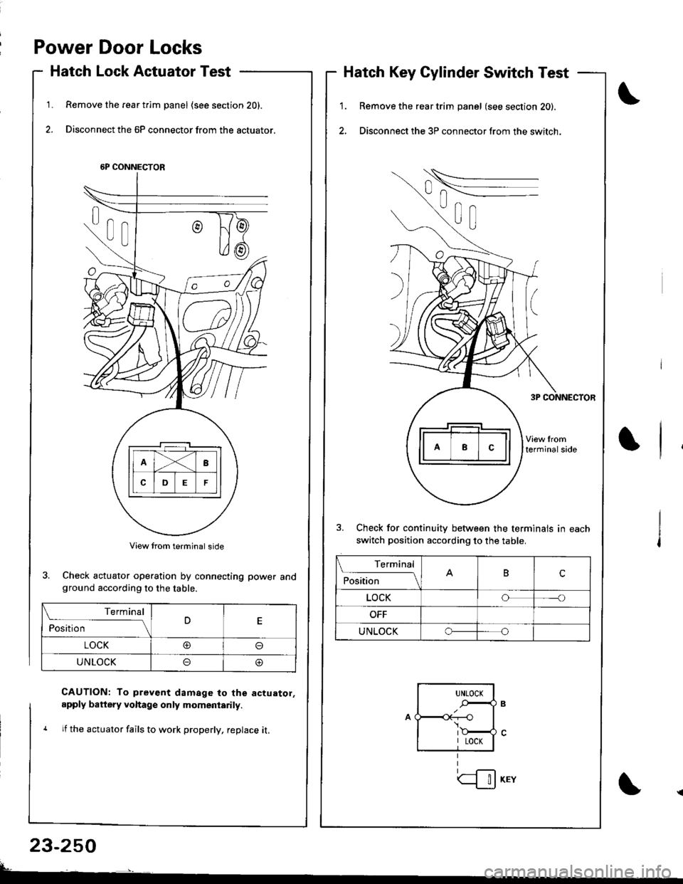
Power Door Locks
Hatch Lock Actuator Test
Remove the rear t.im panel (see section 20).
Disconnect the 6P connector from the actuator.
1.1.
2.
Hatch Key Cylinder Switch Test
Remove the rear trim panel (see section 20).
Disconnect the 3P connector from the switch.
3. Check for continuitv between the terminals in each
switch position according to the table.
6P CONNECTOR
3. Check actuator operation by connecting power andground according to the table.
CAUTION: To prev€nt damage to the actuator,
apply battery voltage only momeniarily.
1 lf the actuator fails to work properly, replace it,
23-250
Terminal
ilil;---tBc
LOCKoo
UNLOCKo
Terminal
ilil;-]E
LOCK@o
UNLOCKoo
UNLOCK
.-,4
I LOCK
| !J KEY