Cylinder HONDA INTEGRA 1998 4.G Manual PDF
[x] Cancel search | Manufacturer: HONDA, Model Year: 1998, Model line: INTEGRA, Model: HONDA INTEGRA 1998 4.GPages: 1681, PDF Size: 54.22 MB
Page 703 of 1681
Power Steering Gearbox
Reassembly {cont'd}
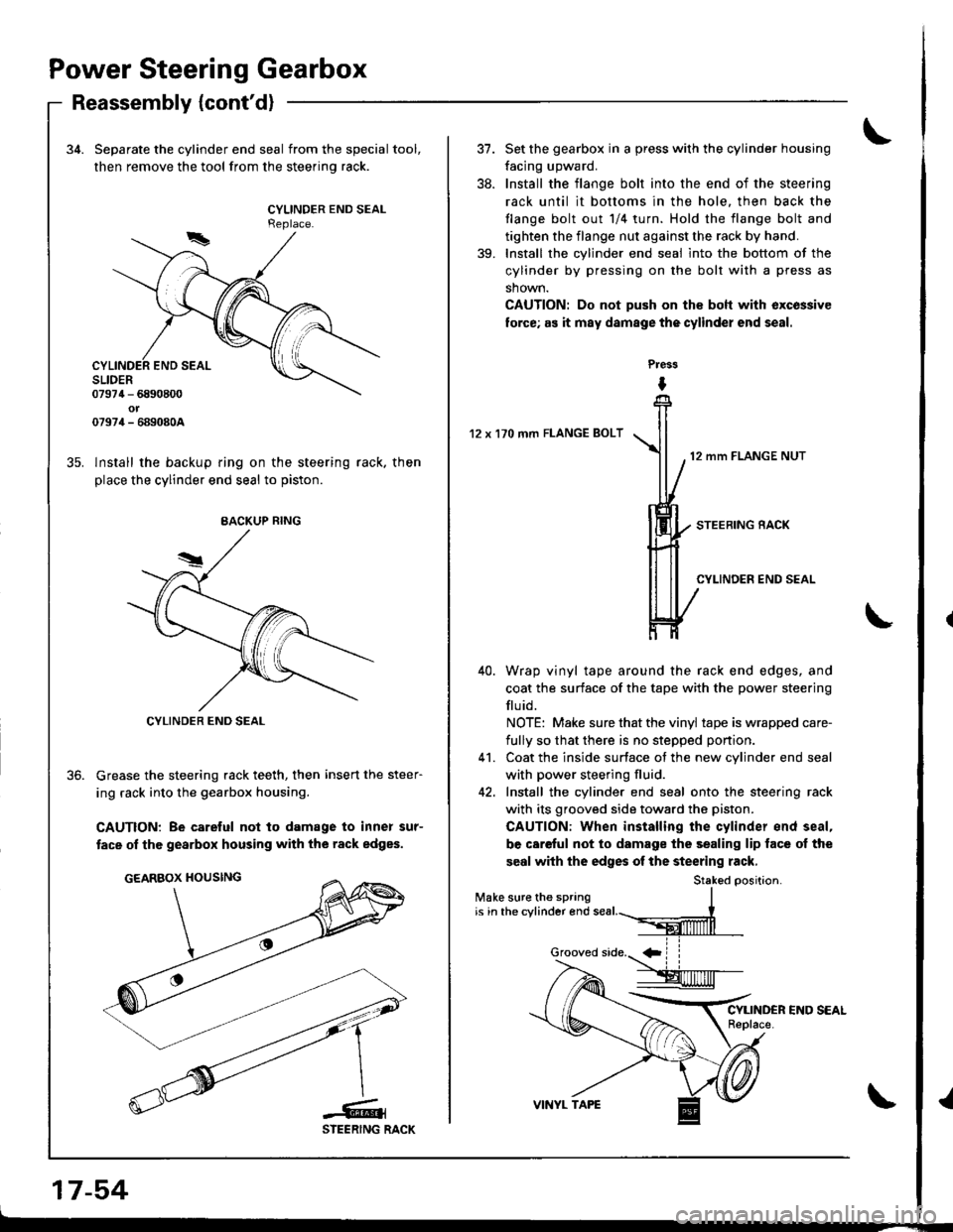
34. Separate the cylinder end seal from the special tool,
then remove the tool from the steerino rack.
CYLINDER END SEALReplace.
lnstall the backup ring on the steering rack. then
place the cylinder end seal to piston.
Grease the steering rack teeth, then insert the steer-
ing rack into the gearbox housing.
CAUTION: Be carelul not to damage to inner sur-
tace of the gearbox housing with the rack edges.
BACKUP BING
CYLINDER END SEAL
17-54
37.
38.
Set the gearbox in a press with the cylinder housing
facing upward.
Install the flange bolt into the end of the steering
rack until it bottoms in the hole. then back the
tlange bolt out 1/4 turn. Hold the flange bolt and
tighten the flange nut against the rack by hand.
Install the cylinder end seal into the bottom of the
cylinder by pressing on the bolt with a press as
shown.
CAUTION: Do not push on th€ boh with excossive
lorce; as it may damage thecylinder end seal.
Press
I
12 x 170 mm FLANGE BOLT
12 mm FLANGE NUT
Wrap vinyl tape around the rack end edges, and
coat the surface of the tape with the power steering
flu id.
NOTE: Make sure that the vinyl tape is wrapped care-
fully so that there is no stepped ponion.
Coat the inside surface of the new cvlinder end seal
with power steering fluid.
Install the cylinder end seal onto the steering rack
with its grooved side toward the piston.
CAUTION: When installing the cylinder end seal,
be careful not to damage the sealing lip face of the
seal with the edges of the steering rack,
Stak6d oosition.
39.
41.
Make sure the springis in the cylinder end
Page 704 of 1681
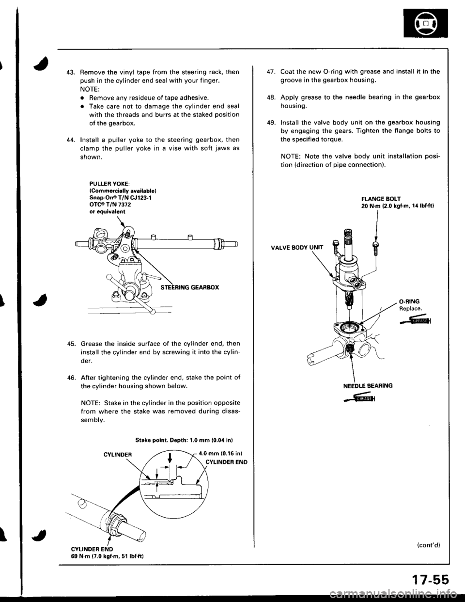
Remove the vinyl tape from the steering rack, then
push in the cylinder end seal with your finger.
NOTE:
. Remove any resideue of tape adhesive.
. Take care not to damage the cylinder end seal
with the threads and burrs at the staked position
of the gearbox.
Install a puller yoke to the steering gearbox, then
clamp the puller yoke in a vise wjth soft jaws as
shown.
PULLER YOKEI{Commcrci.lly .vailablelSn.p-On@ T/N c.r123-1oTc€ T/N 7372or equivalent
Grease the inside surface of the cylinder end. then
install the cylinder end by screwing it into the cylin
der,
After tightening the cylinder end, stake the point of
the cylinder housing shown below.
NOTE: Stake in the cylinder in the position opposite
from where the stake was removed during disas-
semory.
Stake point. Dopth: 1.0 mm (0.04 inl
4.0 mm (0.16 inl
CYLINOER END
46.
\
47.
49.
coat the new o-ring with grease and install it in the
groove in the gearbox housing.
Apply grease to the needle bearing in the gearbox
ho using.
Install the valve body unit on the gearbox housing
by engaging the gears. Tighten the flange bolts to
the specified torque.
NOTE: Note the valve body unit installation posi-
tion (direction of pipe connection).
VALVE BODY UNIT
(cont'd)
O.RINGReplace.
-611
NEEDLE AEARING
-Grl
17-55
Page 705 of 1681
Power Steering Gearbox
Reassembly (cont'dl
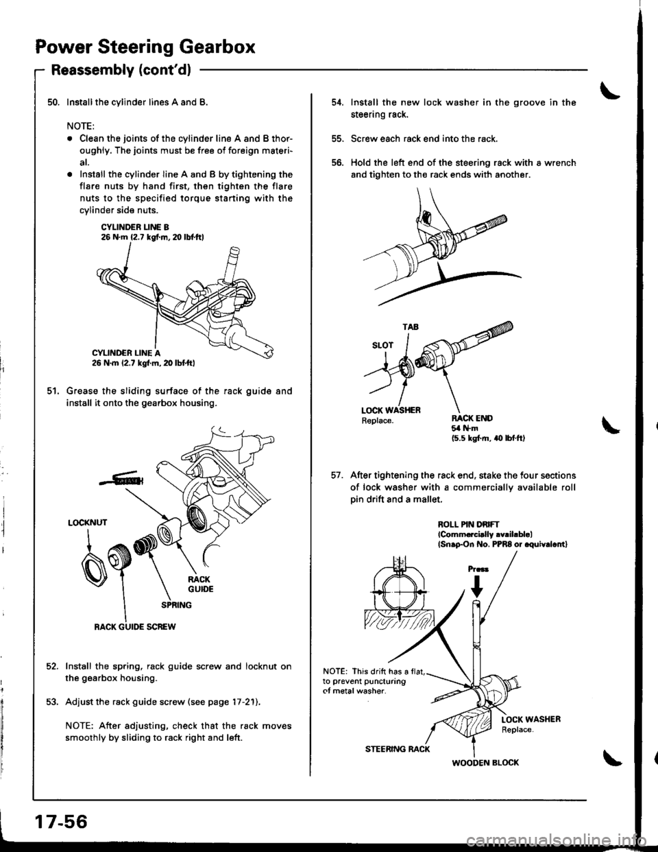
Installthe cylinder lines A and B.
NOTE:
. Clean the joints of the cylinder line A and B thor-
oughly. The joints must be free ol foreign materi-
at.
. Install the cylinder line A and B by tightening the
flar€ nuts by hand first, then tighten the flare
nuts to the specified torque staning with the
cylinder side nuts.
CYLINDER I-INE B26 N.m {2.7 kgf.m, m lbl.ftl
50.
5t.Grease the sliding surface of the rack guide
install it onto the gearbox housing,
and
52.
53.
LOCKNUT
q
SPRING
RACK GUIDE SCREW
Install the spring, rack guide screw and locknut on
the gearbox housing.
Adjust the rack guide screw (see page 17-2'll,
NOTE: After adiusting, check that the rack moves
smoothly by sliding to rack right and left.
17-56
STEERING RACK
WOODEN BLOCK
54.Install the new lock washer in the groove in the
steering rack.
Screw each rack end into the rack.
Hold the left end of the steering rack with I wrench
and tighten to th€ rack ends with another.
56.
After tightening the rack end, stake the four sections
of lock washer with a commerciallv available rollpin drift and a mallet.
RACK END5{ l{.m
{5.5 kgl.m, aO lbt.ftl
ROLL PIN DRIFTlcomm.rci.lly .v.ihbl.l(Sn.pon f{o, PPR8 or .quiv.lc.n}
LOCK WASHERReplace.
NOTE: This dritt has ato prevent puncturingot metal washer.
Page 706 of 1681
59.
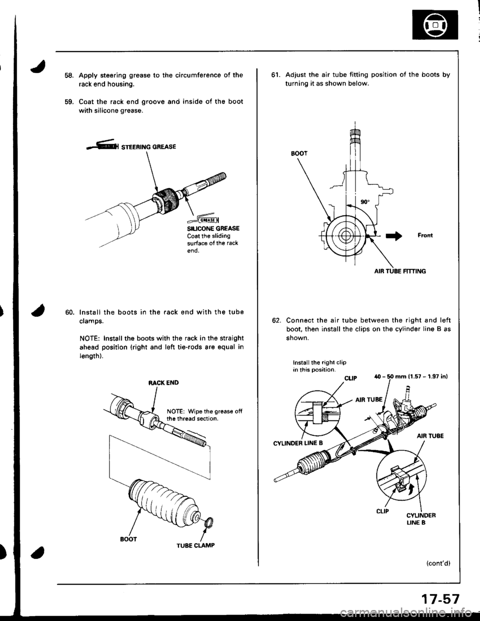
Apply steering grease to the circumference of the
rack end housing.
Coat the rack end groove and inside of the boot
with silicone grease.
-Cl STEERTNG GREASE
SILICONE GBEASECoat the slidingsurface ofthe rack
end.
60.lnstall the boots in the rack end with the tube
clamps.
NOTE: Install the boots with the rack in the straight
ahead position (right and left tie-rods are equal in
length).
RACK END
TUBE CLAMP
17-57
ot.Adjust the air tube fitting position ot the boots by
turning it as shown below.
Connect the air tube between the right and left
boot, then install the clips on the cylinder line B as
snown.
Installthe righi clipin this position.
(cont'd)
mrn 11.57 - 1.97 inl
Page 753 of 1681
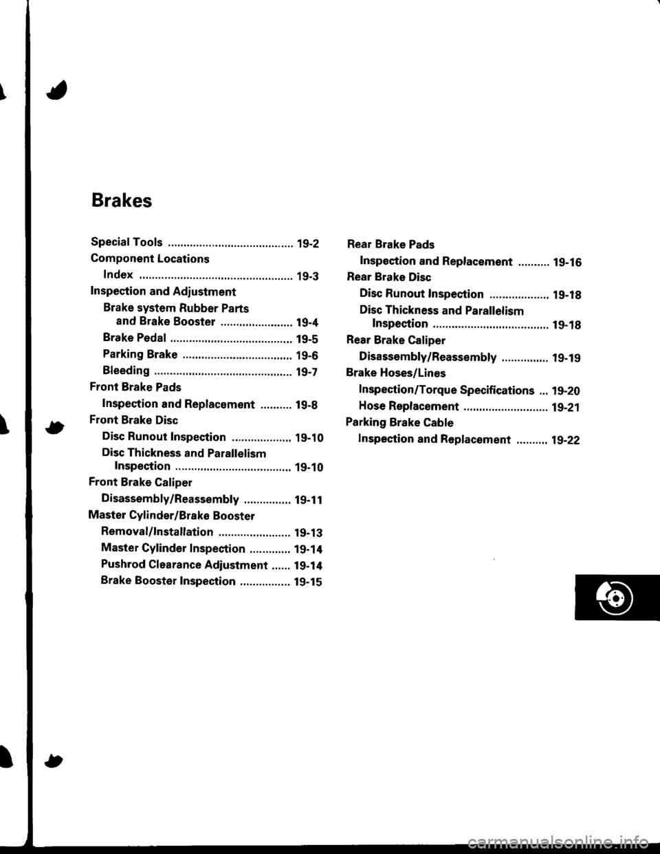
Brakes
Special Tools ............. 19-2
Component Locations
Index ................ ...... 19-3
Inspection and Adiustment
Brake system Rubber Parts
and Brake Booster ....................... 19-4
Brake Pedal ............ 19-5
Parking Brake ........ 19-6
Bleeding ................. t9-7
Front Brake Pads
Inspection and Replacement .......... l9-B
Front Brake Disc
Disc Runout Inspection ................... 19-10
Disc Thickness and Parallelism
Inspection .......... 19-10
Front Brake Caliper
Disassembly/Reassembly ............... l9-1 l
Master Cylinder/Brake Booster
Removal/1nsta|lation ....................... 19-13
Master Cylinder Inspection ............. 19-14
Pushrod Clearance Adjustment ...... 19-14
Brake Booster Inspection,.............,, lg-15
Rear Brake Pads
Inspeetion and Replacement .......... l9-16
Rear Brake Disc
Disc Runout Inspection ................... 1 g-18
Disc Thickness and Parallelism
Inspection .......... t9-18
Rear Brake Caliper
Disassembly/Reassembly ............... l9-19
Brake Hoses/Lines
Inspection/Torque Specifications ... l9-20
Hose Replacement ...................... ..... 19-21
Parking Brake Gable
f nspection and Replacement ,......,.,19-22
Page 755 of 1681
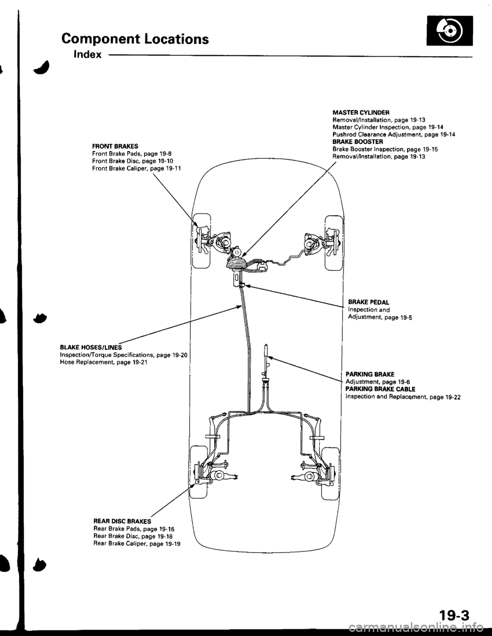
Component Locations
Index
FRONT BRAKESFront Brake Pads, page 19-8Front Brake Disc, page 19-10Front Brake Caliper, page 19-11
BLAKE HOSES/LINESInspection/Torque Specitications. page 19,20Hose Replacement, page 19-21
MASTER CYLINDEBR€moval/lnstallation, pag€ 19-'t3Mast€r Cylinder Inspection, page 19-14Pushrod Cl6aranc6 Adjustment, page 19-14BRAKE BOOSTERBrake Eoostor Inspoction, page 19-15Removal/lnstallation, pags'19-'13
BMKE PEDALlnspection andAdjustment, page 19-5
PARKING ERAKEAdjustment, page'19-6PARKING BRAKE CABLElnspoction and Roplacement, page 19-22
REAR DISC BRAKESRear Brake Pads, page 19-16Rear Brake Disc, page 19-18Rear Brake Caliper, page 19-19
19-3
Page 756 of 1681
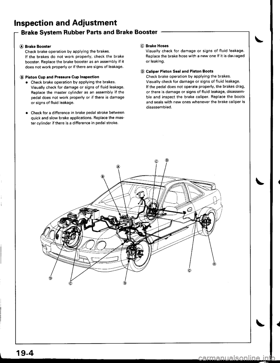
Inspection and Adiustment
Brake System Rubber Parts and Brake Booster
@ Brake Boost€r
Check brake operation by applying the brakes.
lf the brakes do not work properly, check the brake
booster. Replace the brake booster as an assembly if it
does not work properly or if there are signs of leakage
@ Piston cup and Pre3sure cup Inspection
. Check brake operation by applying the brakes.
Visually check for damage or signs of fluid leakage,
Replace the master cylinder as an assembly if the
pedal does not work properly or if there is damage
or signs of fluid leakage.
. Check for a difference in brake pedal stroke betlveen
quick and slow brake applications, Replace the mas-
ter cylinder if there is a difference in pedal stroke.
O Brake Hoses
Visually check for damage or signs of fluid leakage.
Replace the brake hose with a new one if it is darnaged
or leaking.
@ Caliper PBton Seal and Pkton Boots
Check brake operation by applying the brakes.
Visually check for damage or signs of fluid leakage.
lf the pedal does not operate properly, the brakes drag.
or there is damage or signs of fluid leakage, disassem-
ble and inspect the brake caliper. Replace the boots
and seals with new ones whenever the brake caliper is
disassembled.
19-4
Page 759 of 1681
Bleeding
CAUTION:
. Oo not reuse the drsined fluid,
. Always use Genuine Honda DOT 3 Brake Fluid. Using
a non-Honda brake fluid can cause corrosion and
decrease the lile of the system,
a Make sure no dirt or other foreign matt€t is allowed
to contaminate the brske fluid.
. Do not spill brake fluid on tho car, it may damage the
pain; if brake fluid does contact the paint, wash it off
immediately with water.
NOTE: The reservoir on the master cylinder must be at
the MAX (upper) level mark at the start of bleeding pro-
cedure, and checked after bleeding each brake caliper.
Add fluid as required.
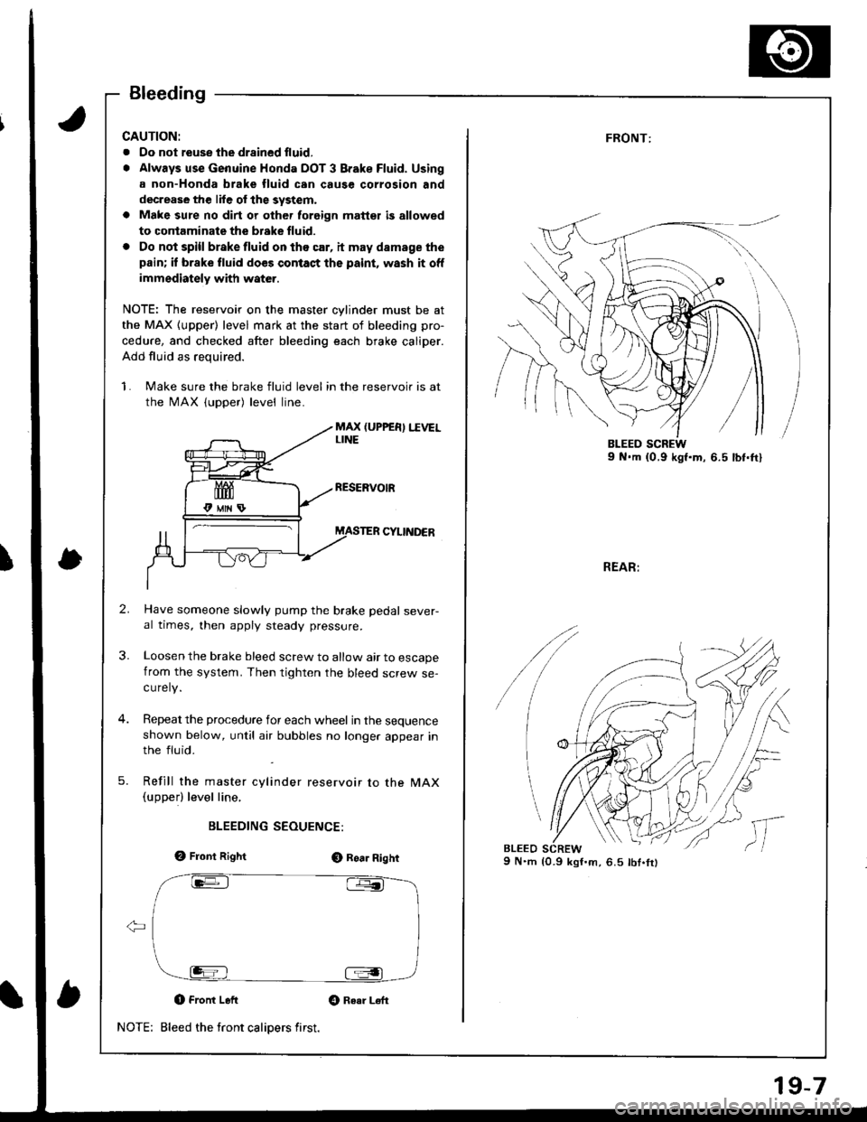
1. Make sure the brake fluid level in the reservoir is at
the MAX (upper) level line.
MAX (UPPER) I.IVELLINE
CYIINDER
Have someone slowly pump the brake pedal sever-al times, then apply steady pressure.
Loosen the brake bleed screw to allow air to escapefrom the system. Then tighten the bleed screw se-curely.
Repeat the procedure for each wheel in the sequenceshown below, until atr bubbles no longer appear inthe fluid.
Refill the master cylinder reservoir to the MAX(upperl level line,
BLEEDING SEOUENCE:
e, Front RightO Roa. Right
O Front Left Gt Raar L€ft
Bleed the front calipers first.NOTE:
19-7
FRONT:
REAR:
9 N.m {0.9 kgI'm,6.5 lbt.fr)
/
lc
,,
l,
Page 765 of 1681
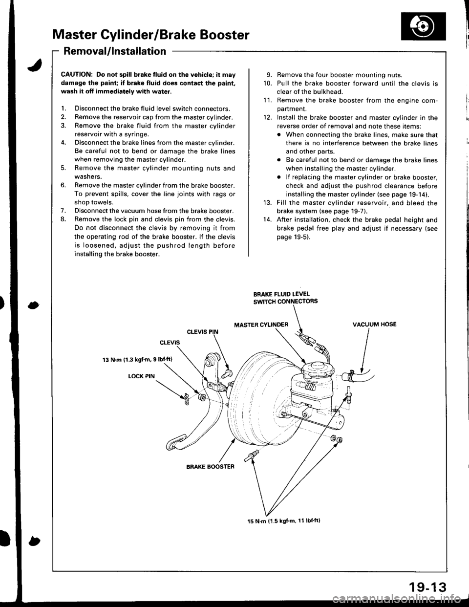
Master Cylinder/Brake Booster
I'RemovaUlnstallation
CAUTION: Do not spill brake tluid on the vehicle; it may
damage the paint; if brake fluid does contact the paint,
wash it oft immediatoly with water.
l. Disconnect the brake fluid level switch connectors.
2. Remove the reservoir cap from the master cylinder.
3. Remove the brake fluid from the master cvlinder
reservoir with a syringe.
4. Disconnect the brake lines from the master cylinder.
Be careful not to bend or damage the brake lines
when removing the master cylinder.
5. Remove the master cylinder mounting nuts and
washers.
6. Remove the master cylinder from the brake booster.
To prevent spills, cover the line joints with rags or
shoD towels.
7. Disconnect the vacuum hose from the brake booster.
8. Remove the lock pin and clevis pin from the clevis.
Do not disconnect the clevis by removing it from
the operating rod of the brake booster. lf the clevis
is loosened, adjust the pushrod length before
installing the brake booster.
13 N.m (1.3 kgf'm, 9 lbl'ft)
LOCX PIN
9. Remove the four booster mounting nuts.
10. Pull the brake booster forward until the clevis is
clear of the bulkhead.
11. Remove the brake booster from the enqine com-
panmenL
12, Install the brake booster and master cylinder in the
reverse order of removal and note these items:
. When connecting the brake lines, make sure that
there is no interference between the brake lines
and other parts.
. Be careful not to bend or damage the brake lines
when installing the master cylinder.
. lf replacing the master cylinder or brake booster,
check and adiust the DUshrod clearance before
installing the master cylinder (see page 19-14).
13. Fill the master cylinder reservoir, and bleed the
brake system (see page 19-7).'14. After installation, check the brake pedal height and
brake pedal free play and adjust if necessary (see
page 19-5).
BRAKE FLUID LEVEL
SW]TCH CONNECTORS
MASTER CYLINOERVACUUM HOSE
J
15 N.m t1.5 kgl'm, 11 lbf'ft)
Page 766 of 1681
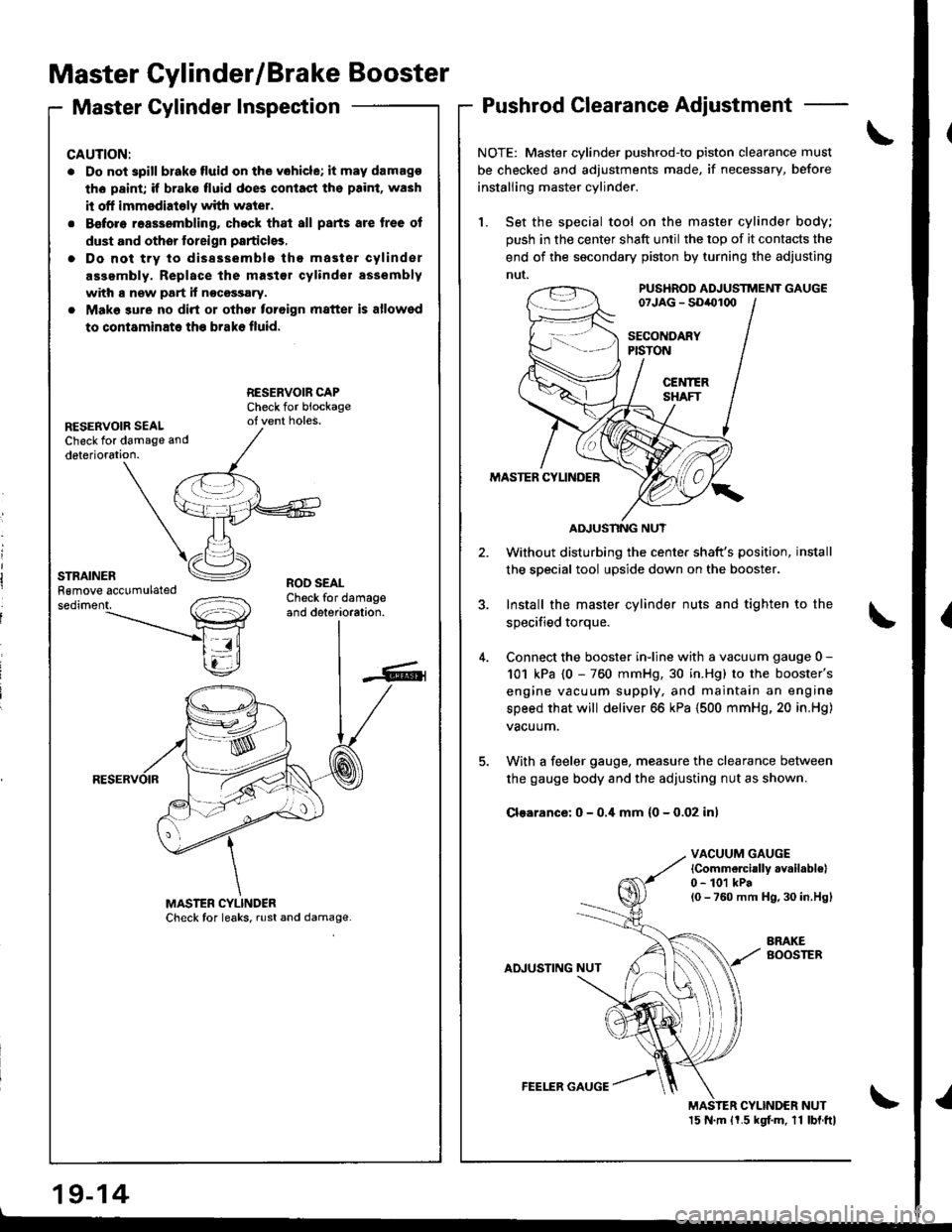
Master Cylinder/Brake Booster
Master Cylinder InspectionPushrod Clearance Adjustment
NOTE: Master cylinder pushrod'to piston clearance must
be checked and adjustments made, if necessary, before
installing master cylinder.
1. Set the special tool on the master cylinder body;
push in the center shaft until the top of it contacts the
end of the socondary piston by turning the adjusting
nut.PUS'IROD ADJUSTTTiENT GAUGE07JAG - SDiOl(xl
SECOITDARYPISTON
CEl{IERSHAFT
MASTER CYLINDER
Without disturbing the center shaft's position,
the soecial tool upside down on the booster.
3. Install the master cylinder nuts and tighten to the
sDecified toroue.
4. Connect the booster inline with a vacuum gauge 0 -
101 kPa {0 - 760 mmHg, 30 in.Hg) to the booster's
engine vacuum supply, and maintain an engine
speed that will deliver 66 kPa (500 mmHg, 20 in.Hg)
vacuum.
5. With a feeler gauge, measure the clearance between
the gauge body and the adjusting nut as shown.
Clsarance: 0 - 0,i[ mm (0 - 0.02 inl
VACUUM GAUGElCommelcially availabl€|0 - 101 kPal0 - 760 mm H9,30 in.Hgl
AINUSTING NUT
BRAKEBOOSTEB
MAS'ER CYLINDER NUT15 N.m ll.5 kgf.m. 11 lbl.ftl
CAUTION:
. Do not spill blake fluid on the vohicle; it may damago
th6 paint; if brake fluid does contast ths paint, wash
it off immsdiately with water.
. Before reassembling. chock that all parts are tree of
dust and othor toreign particlgs,
. Do not trv to dissssemblo the master cylinder
assembly. Replace the mast€r cylinder assembly
with s new part if nocossary.
. Make sure no dirt or othor toroign matter is allowed
to contaminate th€ brako fluid.
RESERVOIR SEALCheck for damage and
deterioration.
ROD SEALCheck for damageand deterioration.
AIIUSNNG NUT
19-14
FEELER GAUGE