Cylinder HONDA INTEGRA 1998 4.G Owners Manual
[x] Cancel search | Manufacturer: HONDA, Model Year: 1998, Model line: INTEGRA, Model: HONDA INTEGRA 1998 4.GPages: 1681, PDF Size: 54.22 MB
Page 834 of 1681
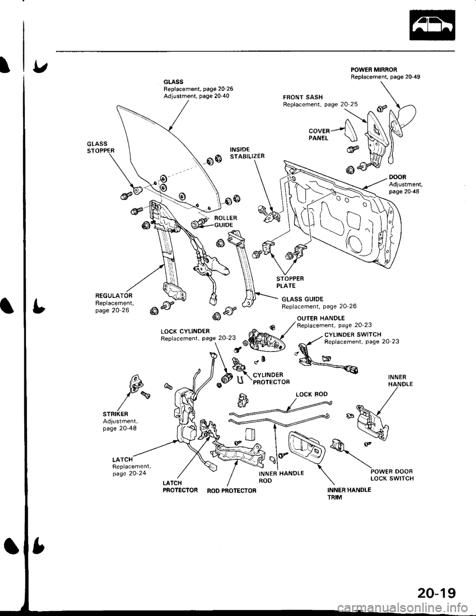
GLASSFeplacement, page 20'26Adjustment, page 20-40
POWER MIRRORReplacement, page 20-49
oooRAdjustment,page 20-48
FBONT SASHReplacement, page 20 25
"oura---f\PANEL \.IJGLASSSTOPPER
@
REGULATORReplacement,page 20 26
ROLLER
LOCK CYLINDENReplacement, Page 20'23
GLASS GUIDEReplacement, page 20-26
OUIER HANDLE
STOPPEBPLATE
@6r-.6f@J
dll
CYLINDERPNOTECTOR
INNER HANDLEROD
Replacement. page 20'23
INNER HANDLETRIM
_. cYLINDER SWITCH
-,y' Replacement. page 20 23
"q
@<€
INNER6\,
tp
)rw
STRIKERAdiustment,page 20-48
%
LATCHReplacement,page 20'24
@
d
LOCK ROD
PROTECTOR RoDPRoTEcToR
20-19
Page 839 of 1681
Doors
Outer HandleReplacement (cont'd)
irl
lii
,l
r
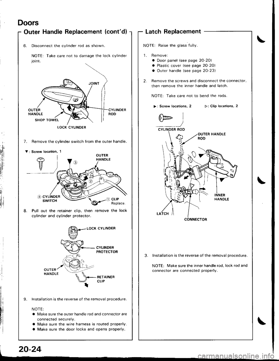
LatchReplacement
NOTE: Raise the glass fully.
1. Remove:
a Door panel (see page 20 20)
a Plastic cover (see page 20 20)
a Outer handle (see page 20'23)
2- Remove the screws and disconnect the connector,
then remove the inner handle and latch.
NOTEr Take care not to bend the rods.
> | Screw locations, 2
6bD l
:)CYLINDER ROO
>: Clip locaiions, 2
3.Installation is the reverse of the removal procedure.
NOTE: Make sure the inner handle rod, lock rod and
connector are connected properly.
6.
7.
v:
Disconnect the cylinder rod as shown.
NOTE: Take care not to damage the lock cylinder
Jornt.
OUTERHANDLE
SHOP TOWEL
Remove the cylindef switch from the outer handle.
Pull out the retainer clip, then remove the lock
cylinder and cylinder protector.
8.
L
g--.-.o"*
cYLTNDER
lnstallation is the reverse of the removal procedure.
NOTE:
a Make sure the outer handle rod and connector are
connected securely.
a Make sure the wire harness is routed properly.
a Make sure the door locks and opens properly.
LOCK CYLINOEB
Page 928 of 1681
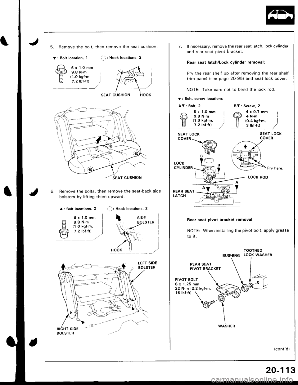
5. Remove the bolt, then remove the seat cushion.
i -,: Hook locations, 2v: Boli location, 1
6.
6 x l.0 mm9.8Nm{1.0 kg{ m,7.2 tbf {r)
6 x 1.0 mm
F s.sN.Fl t1 .o ksl m.
cR 7.2 rbf.frr l./\---l
Remove the bolts, then remove the seat back side
bolsters by lilting them upward.
: Soft locations, 2 r '1: Hook locations, 2
iSIDEBOLSTER
r,1F=
8V: Screw, 2
4x0.7mm4 N.m
{0.4 kgf m, Is ttt.ttl ,/
SEAT LOCKCOVER
Rea, seat pivot bracket removal:
NOTE: When installing the pivot bolt, apply grease
to it.
TOOTHED
BUSHTNG LOCK WASHER
7. lf necessary, remove the rear seat latch, lock cylinder
and rear seat pivot bracket.
Reai seat latch/Lock cylinder femoval:
Pry the rear shelf up after removing the rear shelf
trim panel (see page 20 95) and seal lock cover.
NOTE: Take care not to bend the lock rod.
V: Bolt, screw locations
AV: Bolt, 2
6x1.0mm I9.8 N.m I
!l' {1.0 kgf m, Iv 7.2tbt4l]� //
SEAT LOCKcovER\>#\
wr'\[FIJB.
REAR SEATPIVOT BRACKET
PIVOT BOLT
22 N.m 12.2 kgf.m.16 tbf.Ir)
LOCKCYLINDER
REAR SEATLATCH
Pry here.
WASHER
20-113
Page 972 of 1681
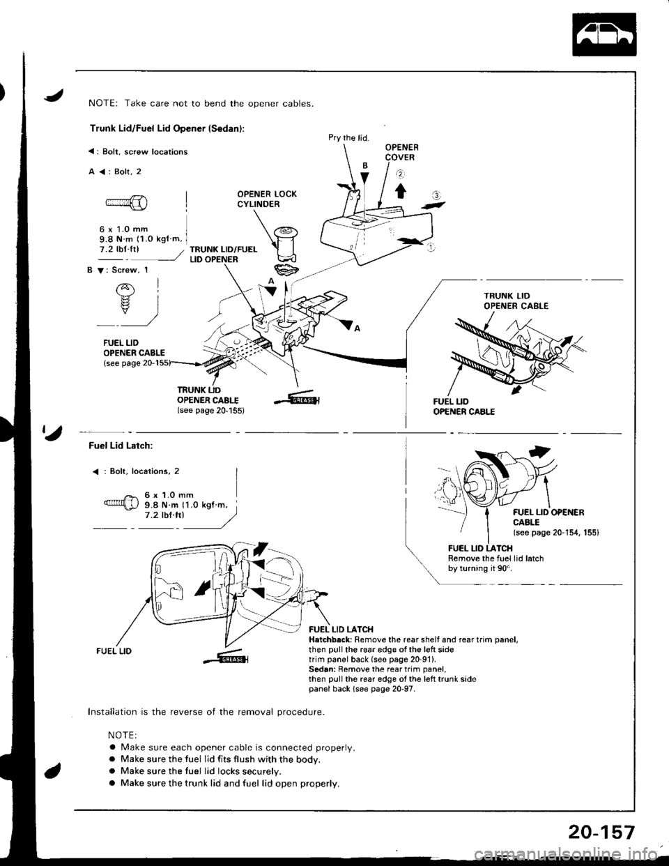
NOTE: Take care not to bend the opener cables.
Trunk Lid/Fuel Lid Opener lSedan):
<: Bolt, screw locations
A<:Bolt,2
OPENER LOCKCYLINDER
6 x 1.0 mm9.8 N m 11.o kgf m,
TRUNK LID/FUELLID
OPENER CABLE{see page 20-1
OPENERCOVER
z
tat-
7.2 tbt.trl /
B V: Screw, 1
rql.b.rz
rs? IY)
FUEL LID
TRUNK UDOPENER CABI.I(see page 20'155)
Pry the lid.
ta
Fuel Lid Latch:
: Bolt, locaiions, 2
6 x 1.O mm9.8 N.m 11.0 kgt m,7.2 tbl.trl J/)
FUEL LID OPEiIERCABLE(see page 20-154, 155)
FUEL LID LATCHRemove the fuel lid latchby turning it 90'.
FUEL LIO
Installation is the reverse of the removal procedure.
NOTEI
a Make sure each opener cable is connected properly.
a Make sure the fuel lid fits flush with the body.
a Make sure the tuel lid locks securely.
a Make sure the trunk lid and fuel lid open properly.
FUEL LID LATCHHatchbsck: Remove the rear shell and rear trim oanel,then pull the 196r edge of the left sidetrim panel back (see page 20-91).Sedan: Remove the rear trim panel,then pull the rear edge ol the left trunk sidepanel back (s€e page 20-97.
20-157
Page 973 of 1681
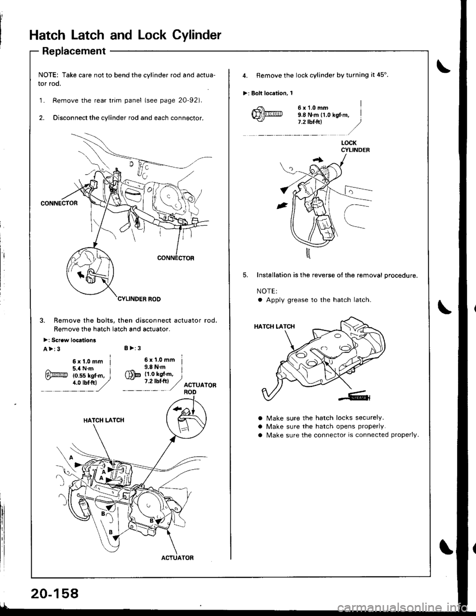
Hatch Latch and Lock Cylinder
Replacement
NOTE: Take care not to bend the cylinder rod and actua-
tor rod.
1. Remove the rear trim panel (see page 20-921.
2. Disconnect the cylinder rod and each connector.
CONNECTOR
3. Remove the bolts. then disconnect actuator rod.
Remove the hatch latch and actuator.
>: Screw loc6tion3
A>:3I >:3
ACTUATOR
20-158
4. Remove the lock cylinder by turning it 45".
>: Bolt location, 1
6x1.omm I9.8 N.m 11,0 kst m, il.ztb$ft| .)
lt: /
LOCKCYLINDEB
Installation is the reverse of the removal procedure.
NOTE:
a Apply grease to the hatch latch
a
a
a
Make sure the hatch locks securely.
Make sure the hatch opens properly.
N4ake sure the connector is connected properlV.
Page 974 of 1681
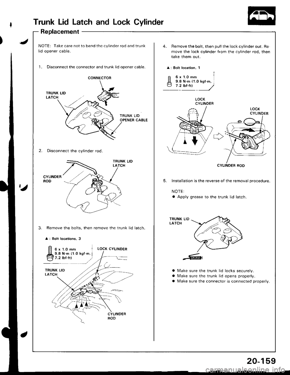
Trunk Lid Latch and Lock Cylinder
Replacement
JNOTE: Take care not to bend the cylinder rod and trunk
lid opener cable.
1. Disconnect the connector and trunk lid opener cable.
4. Remove the bolt, then pull the lock cylinder out. Re
move the lock cylinder {rom the cylinder rod, then
take them out.
: Bolt location, 1
CONNECIOR
LOCKCYLINDER
r>'
2. Disconnect the cylinder rod.
CYLINDERROD
CYLINOER ROD
5. lnstallation is the reverse of the removal procedure.
NOTE:
a Apply grease to the trunk lid latch.
Remove the bolts, then remove the trunk lid
: Boli locations, 3
TRUNK LIDLATCH
3.latch.
6x1.0mm ILOCK CYLINDER
9.8 N.m 11.0 kgf m, I
:t"r': -/
a
a
a
Make sure the trunk lid locks securely.
N/ake sure the trunk lid opens properly.
Make sure the connector is connected properly.
20-159
Page 1085 of 1681
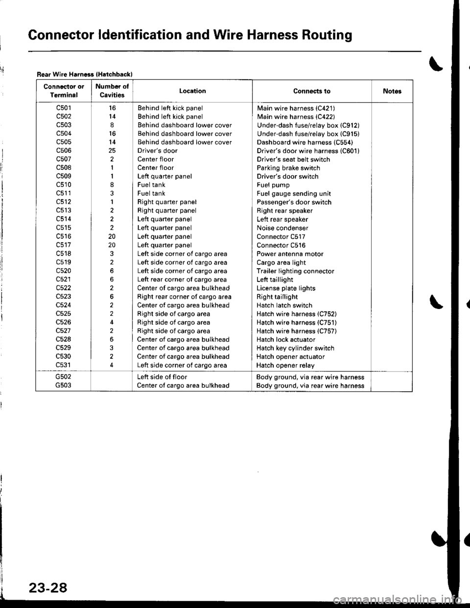
Gonnector ldentification and Wire Harness Routing
Rear Wire Harngss {Hatchbackl
Connector or
Terminal
Number of
C8vitiesLocationConnec{s toNotos
c501
c502
c504
c505
cs06
c507
c508
c509
c510
c51 1
c512
c513
c514
c515
uc to
c518
c519
c520
c522
c524
c528
c529
c530
c531
l6
14
8
16
14
2
1
I
8
3
1
2
2
2
20
20
2
2
6
2
2
2
3
4
Behind left kick panel
Behind left kick panel
Behind dashboard lower cover
Behind dashboard lower cover
Behind dashboard lower cover
Driver's door
Center floor
Center floor
Left quarter panel
Fuel tank
Fuel tank
Right quarter panel
Right quarter panel
Left quarter panel
Left quarter panel
Left quaner panel
Left quarter panel
Left side corner of cargo area
Left side corner of cargo area
Left side corner of cargo area
Left rear corner of cargo area
Center of cargo area bulkhead
Right rear corner of cargo area
Center of cargo area bulkhead
Right side of cargo area
Right side of cargo area
Right side of cargo area
Center of cargo area bulkhead
Center of cargo area bulkhead
Center of cargo area bulkhead
Left side corner of cargo area
Main wire harness {C421)
Main wire harness {C422)
Underdash fuse/relay box (C912)
Underdash fuse/relay box (C915)
Dashboard wire harness (C554)
Driver's doo. wire harness (C601)
Driver's seat belt switch
Parking brake switch
Driver's door switch
Fuel pump
Fuel gauge sending unit
Passenger's door switch
Right rear speaker
Left rear speaker
Noise condenser
Connector C517
Connector C516
Power antenna motor
Cargo area light
Trailer lighting connector
Left taillight
License plate lights
Right taillight
Hatch latch switch
Hatch wire harness (C752)
Hatch wire harness (C751)
Hatch wire harness (C757)
Hatch lock actuator
Hatch key cylinder switch
Hatch opener actuator
Hatch opener relay
Left side of floor
Center of cargo area bulkhead
Body ground, via rear wire harness
Body ground. via rear wire harness
riI
Page 1091 of 1681
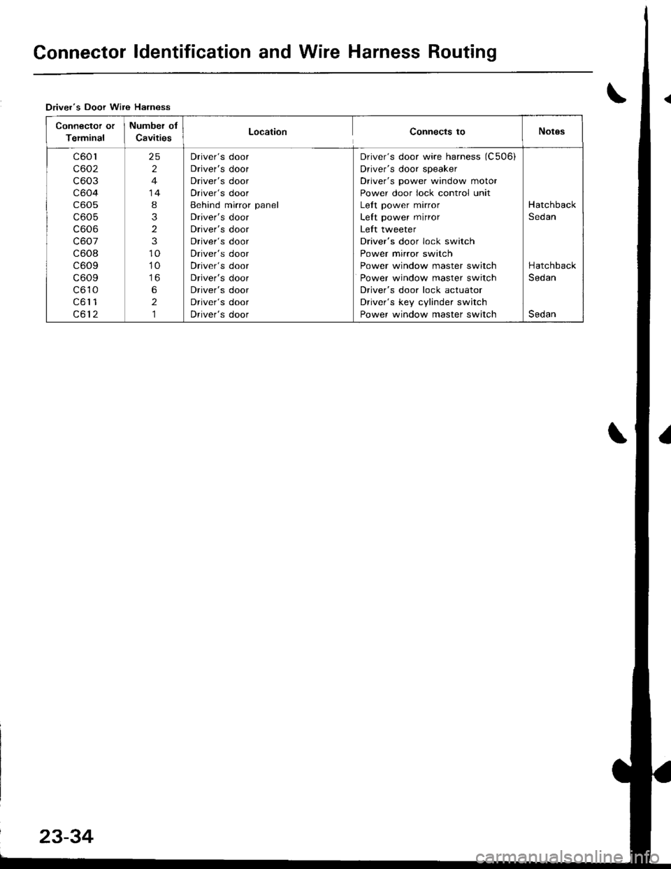
Connector ldentification and Wire Harness Routing
Driver's Door Wire Harness
Connector or
Terminal
Number of
CavitiesLocationConnects toNotgs
c601
c602
c603
c604
c605
c605
c606
c607
c608
c609
c609
c610
c61 1
c612
25
2
4
14
8
3
2
3
10
10
to
6
2,]
Driver's door
Driver's door
Driver's door
Driver's door
Behind mirror panel
Driver's door
Driver's door
Driver's door
Driver's door
Driver's door
Driver's door
Driver's door
Driver's door
Driver's door
Driver's door wire harness (C506i
Driver's door speaker
Driver's power window motor
Power door lock control unit
Left power mirror
Left power mirror
Left tweeter
Driver's door lock switch
Power mirror switch
Power window master switch
Power window master switch
Driver's door lock actuator
Driver's key cylinder switch
Power window master switch
Hatchback
Sedan
Hatchback
Sedan
Sedan
Page 1093 of 1681
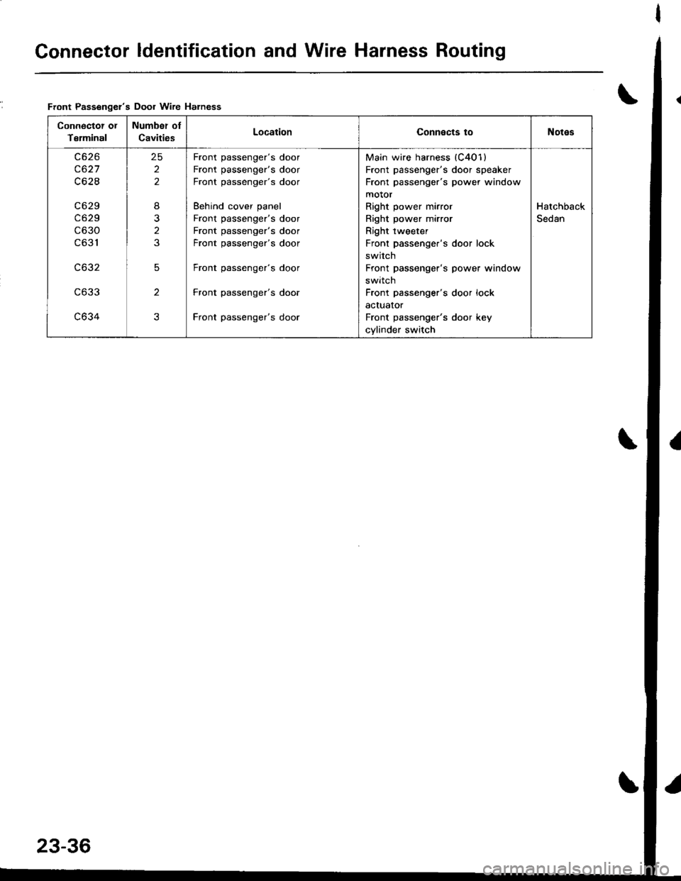
Connector ldentification and Wire Harness Routing
\Front Passengel's Door wire Harness
Connoctot ot
Terminal
Number oI
CavitiesLocationConnects toNotes
c627
c62I
c6 29
c629
c630
c631
c632
c633
c634
25
2
2
8
2
3
5
2
3
Front passenger's door
Front passenger's door
Front passenger's door
Behind cover panel
Front passenger's door
Front passenger's door
Front passenger's door
Front passenger's door
Front passenger's door
Front passenger's door
Main wire harness (C401)
Front passenger's door speaker
Front passenger's power window
motor
Right power mirror
Right power mirror
Right tweeter
Front passenger's door lock
switch
Front passenger's power window
swrrcn
Front passenger's door lock
actuator
Front passenger's door key
cylinder switch
Hatchback
Sedan
Page 1120 of 1681
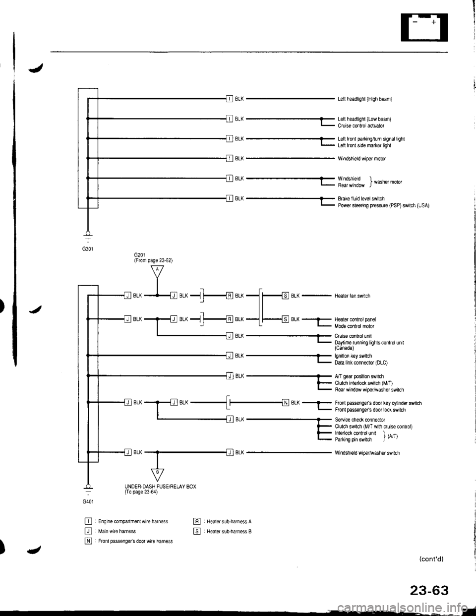
J
BrK-
BrK---
Lell headlighl {High beam)
Lell headlighl (Low beam)Cruise conlro aclualor
Lell lrcfl parkirElurn signallighlLell lront slde maker lighl
Windshield wiper molor
Wndshleld )I Wasner molor
Brake lluid level switchPower sleenng pressure (PSP)swilch (USA)
BLK - Healer lanswlch
J
EL^- Enrlron {€y swrcn- Data [nk conneclor |DLC)
BL(
Fronl passenge/s door key cylinder switdrFronl passonger's door lock swilch
Seavice cieck conneclorClulch swilch (MIT wilh crLr se conlrol)Inle ock contfolunit l ,^-,Parking prn swlch J u' t
Windshi€ld wipefl^Iasher sw 1ch
G40l
tr
tr
N
: Eng ne companmentwife harness
: Fronl passenge/s door wire hamess
: Healer sub.harness A
: Healer sutsharness B
tr
4)(cont'd)
G3o1
(From page 23-62)
;L^ ------ A/T gear posrron sw cn
l- Cldch inledock sw cl rM/.'- Fear window w pe,,wdsl'er sw cl
_l__{BLK_-
UNDER.OASH FUSE/RELAY BOX(To page 23 64)