Cylinder HONDA INTEGRA 1998 4.G Manual Online
[x] Cancel search | Manufacturer: HONDA, Model Year: 1998, Model line: INTEGRA, Model: HONDA INTEGRA 1998 4.GPages: 1681, PDF Size: 54.22 MB
Page 767 of 1681
1.
8.
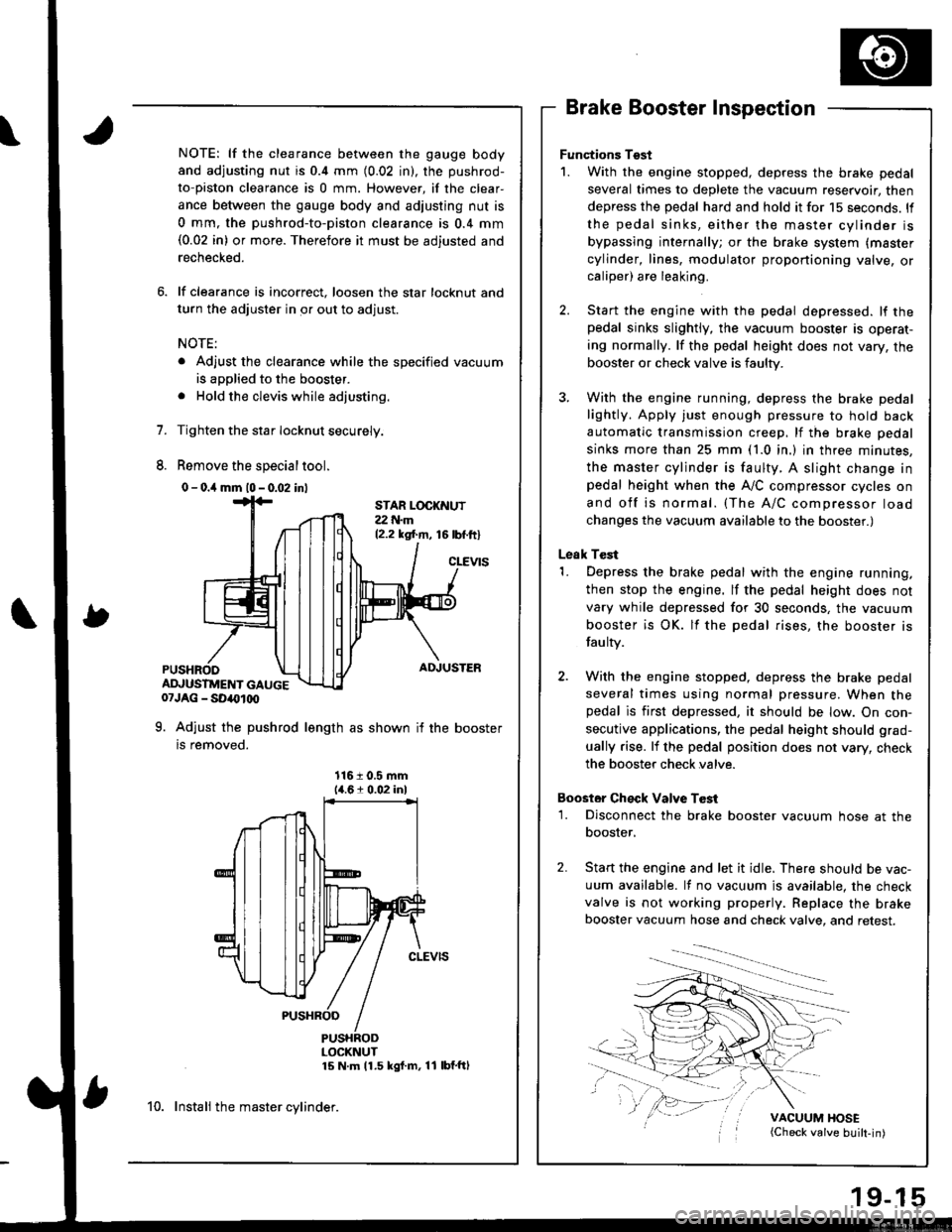
NOTE: lf the clearance between the gauge body
and adjusting nut is 0.4 mm (0.02 in), the pushrod-
to-piston clearance is 0 mm. However, if the clear-
ance between the gauge body and adjusting nut is
0 mm, the pushrod-to-piston clearance is 0.4 mm(0.02 in) or more. Therefore it must be adjusted and
rechecked.
lf clearance is incorrect, loosen the star locknut and
turn the adjuster in or out to adjust.
NOTE:
. Adjust the clearance while the specified vacuum
is applied to the booster.
. Hold the clevis while adjusting.
Tighten the star Iocknut securely.
Remove the special tool.
0 - o.il mm l0 - 0.02 inl
Brake Booster Inspection
Functions Tgst
1. With the engine stopped, depress the brake pedal
several times to deplete the vacuum reservoir, then
depress the pedal hard and hold it for 15 seconds. ll
the pedal sinks, either the master cylinder is
bypassing internally; or the brake system (master
cylinder, lines, modulator proportioning valve, orcaliper) are leaking.
Start the engine with the pedal depressed. lf thepedal sinks slightly, the vacuum booster is operat-
ing normally. lf the pedal height does not vary, the
booster or check valve is faulty.
With the engine running, depress the brake pedal
lightly. Apply just enough pressure to hold back
automatic transmission creep, lf the brake pedal
sinks more than 25 mm (1.0 in.) in three minutes,
the master cylinder is faulty. A slight change inpedal height when the A,,/C compressor cycles on
and off is normal. (The A/C compressor load
changes the vacuum available to the booster.)
Leak Test
1. Depress the brake pedal with the engine running,
then stop the engine. lf the pedal height does not
vary while depressed for 30 seconds, the vacuum
booster is OK. lf the pedal rises, the booster is
fau lty.
2. With the engine stopped, depress the brake pedal
several times using normal pressure. When thepedal is first depressed, it should be low. On con-
secutive applications, the pedal height should grad-
ually rise. lf the pedal position does not vary, check
the booster check valve.
Boostor Ch€ck Valve T6st
1. Disconnect the brake booster vacuum hose at the
booster,
Start the engine and let it idle. There should be vac-
uum available. It no vacuum is available. the check
valve is not working properly. Replace the brake
booster vacuum hose and check valve, and retest.
VACUUM HOSE(Check valve built-in)
STAR LOCKNUT22 t{.m12.2 ksl.m, 16lbf.ftl
cLEVtS
ADJUSTER
ADJUSTMENT GAUGE07JAG - SD40t00
9. Adjust the pushrod length as shown if the booster
is removed.
1161 0.5 mm14.61 0.02 inl
PUSHRODLOCKNUT15 N m 11.5 kgf m, 11 lbf'ftl
10. Instali the master cylinder.
Page 769 of 1681
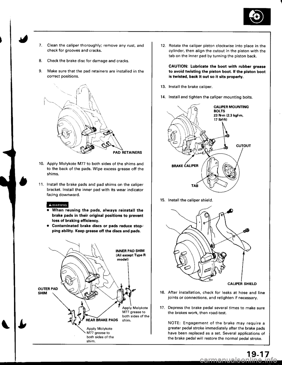
7.Clean the caliper thoroughly; remove any rust, and
check for grooves and cracks.
Check the brake disc for damage and cracks.
Make sure that the pad retainers are installed in the
correct positions.
PAD RETAINERS
Apply Molykote M77 to both sides of the shims and
to the back of the pads, Wipe excess grease off the
snrms.
Install the brake pads and pad shims on the caliper
bracket. Install the inner pad with its wear indicator
facing downward.
r When reusing the pads, always reinstall the
brake pads in their original positions to prsvent
loss of braking efficiency.
. Contaminated brake discs or pads reduce stop,ping ability. Keep grease off the discs and pads.
1 '�I.
INNER PAO SI{IM
lAll oxcopt Typo Rmod.ll
Apply Molykote[I77 grease toboth sides of thePADS shim.
Apply MolykoteM77 grease toboth sides of the
Rotate the caliper piston clockwise into place in the
cylinder, then align the cutout in the piston with the
tab on the inner pad by turning the piston back.
CAUTION: Lubricato th€ boot with rubbor grease
to avoid twisting the piston boot. lf the piston boot
is twist€d, back it out so it sits properly.
Install the brake caliper.
lnstall and tighten the caliper mounting bolts,
15. Installthe caliper shield.
CALIPER SHIELD
After installation, check for leaks at hose and linejoints or connections, and retighten if necessary.
Depress the brake pedal several times to make sure
the brakes work, then road-test.
NOTE: Engagement of the brake may .equire agreater pedal stroke immediately after the brake pads
have been replaced as a set. Several applications of
the brake pedal will restore the normal pedal stroke.
13.
14.
16.
't7.
19-17
Page 772 of 1681
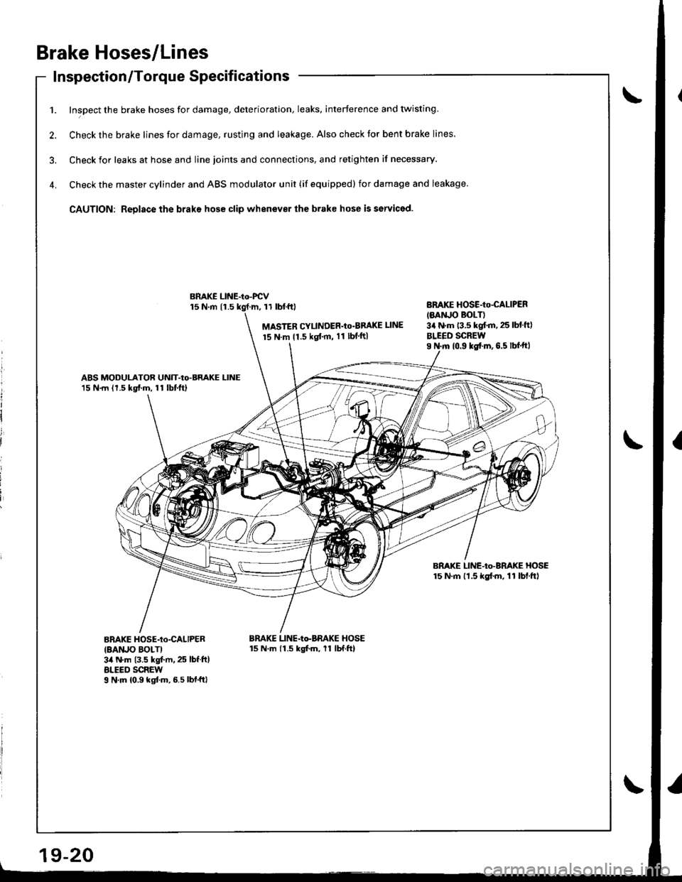
Brake Hoses/Lines
Inspection/Torque Specif icationsInspecuon/ | orque Dpecl carlon
1. Inspect the brake hoses for damage, deterioration, leaks, interference and twisting
2. Check the brake lines for damage, rusting and leakage. Also check tor bent brake lines.
3. Check ior leaks at hose and line joints and connections, and retighten if necessary.
4. Check the master cylinder and ABS modulator unit (if equipped) for damage and leakage.
CAUTION: Replace the braks hose clip whenever the brake hose is serviced.
15 N.m 11.511 tbl.f0
MASTER CYLINDER'Io'BBAKE UNE
15 N.m {1.5 kgt'm, 11 lbf ft}
BnAKE HOSE-Io-CALIPER
IMNJO BOLTI3a N'm 13.5 kgf.m. 25 lbl ft)
BLEED SCREWI N.m 10.9 ks{.m,6.5 lbf.ftl
ABS MODULATOR UNIT-Io-BRAKE LINE15 N.m (1.5 kg{.m, 11 lbtftl
BRAKE LINE-Io-BRAKE HOSE15 N'm lt.5 kgf.m, 11 lbf.ftl
BnAKE HOSE-Io-CALIPER
IBAruO BOLTI3il N.m (3.5 kgt m, 25 lbf.ft)ALEED SCREWI N'm 10.9 kgtm,6.5lbf.ftl
BRAKE LINE-Io-BRAKE HOSE15 N.m 11.5 kgfm, 11 lbf.ftl
BMKE LINE-Io-FCV
l
It
I
i
i
i
Page 780 of 1681
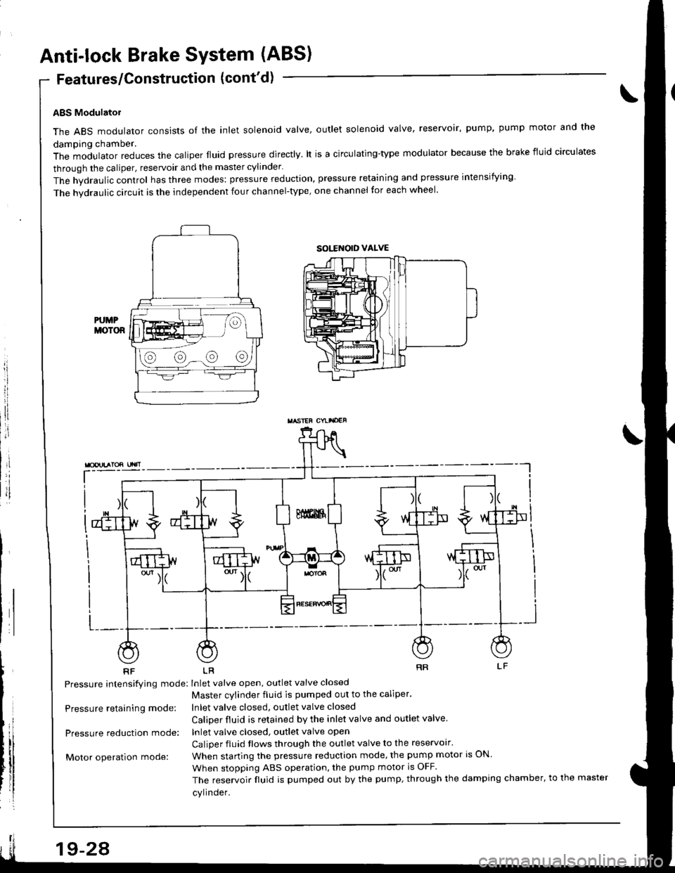
Anti-lock Brake System (ABS)
Features/Construction (cont'd)
ABS Modulatol
The ABS modulator consists of the inlet solenoid valve, outlet solenoid valve, reservoir, pump, pump motor and the
damping chamber.
The modulator reduces the caliper fluid pressure directly. lt is a circulating-type modulator because the brake fiuid circulates
through the caliper, reservoir and the master cylinder.
The hydraulic control has three modes: pressure reduction, pressure retaining and pressure intensiiying
The hvdraulic circuit is the independent four channel-type, one channel tor each wheel'
L-__
RF LR
Pressure intensifying mode: Inlet valve open, outlet valve closed
Master cvlinder fluid is pumped out to the caliper.
Inlet valve closed, outlet valve closed
Caliper fluid is retained by the inlet valve and outlet valve.
lnlet valve closed, outlet valve open
Caliper fluid flows through the outlet valve to the reservolr'
When starting the pressure reduction mode, the pump motor is ON.
When stopping ABS operation, the pump motor is OFF.
The reservoir fluid is pumped out by the pump, through the damping chamber, to the master
cylinder.
\
Pressure retaining mode:
Pressure reduction mode:
Motor operation mode:
sott orD vALvE
@@-@@
TASIEF CYLI'OEF
19-24
Page 788 of 1681
Troubleshooting Precautions
Kickback
L The motor operates when the ABS is functioning, and the fluid in the reservoir is forced out to the master cylinder,
causing kickback at the brake pedal.
Pump Motol
1. The pump motor operates when the ABS is functioning.
2. The ABS control unit checks the pump motor operation during initial diagnosis and when the vehicle is started. You
mav hear the motor operate at this time, but it is normal
Brake Fluid Replacement/Air Bleeding'1. Brake fluid replacement and air bleeding procedures are the same as vehicles without ABS. To ease bleeding, start
with the front wheels.
Troubleshooting
1. The troubleshooting flowcharts procedures assume that the cause of the problem is still present and the ABS indica-
tor is still on. Following the flowchart when the ABS indicator does not come on can result in incorrect diagnosis.
2. Ouestion the customer about the conditions when the problem occurred, and try to reproduce the same conditions
for troubleshooting.
Find out when the ABS indjcator came on. such as during initial diagnosis. during ABS control, after ABS control,
when vehicle speed was at a certain speed, etc.
3, When the ABS indicator does not come on during the test-drive, but troubleshooting is performed based on the DTC,
check for loose connectors, poor contact at the terminals, etc. before you start troubleshooting'
4. After troubleshooting, erase the DTC and test-drive the vehicle. Be sure the ABS indicator does not come on.
5. The connector illustrations show the female terminals with a single outline and the male terminals with a double outline.
Page 813 of 1681
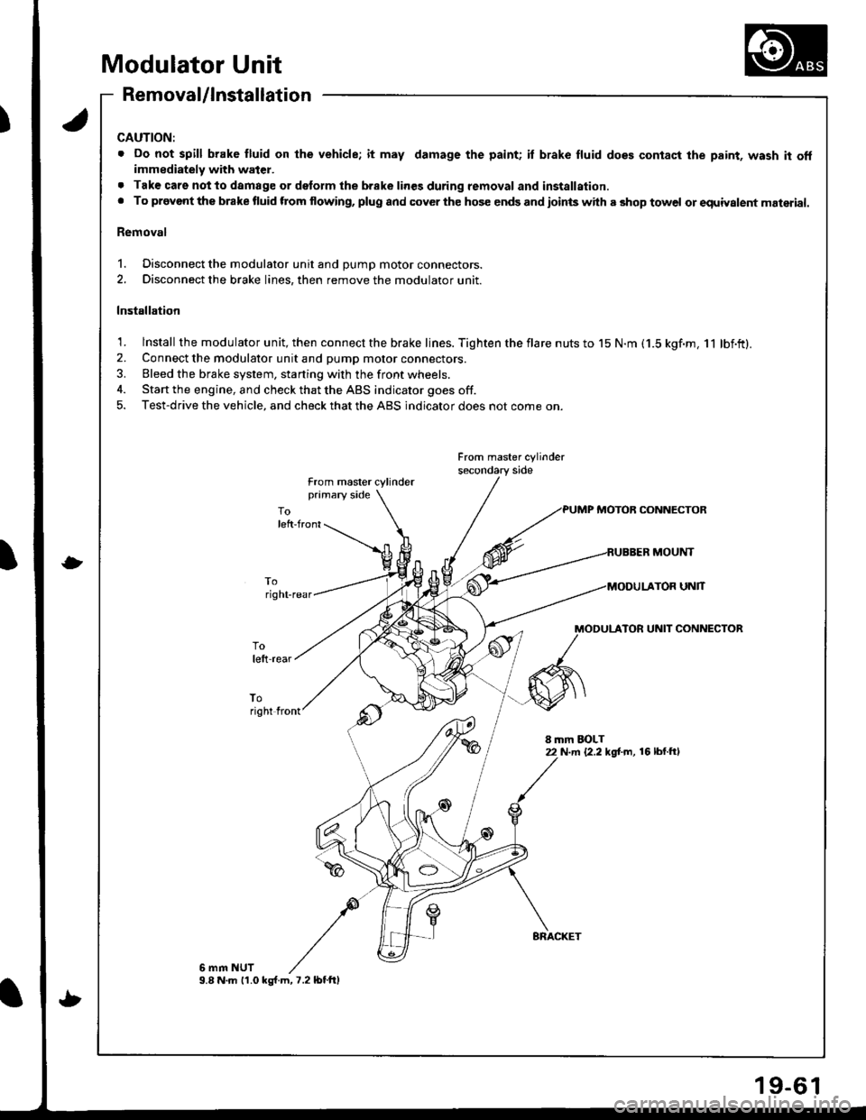
Modulator Unit
Removal/lnstallation
CAUTION:
. Do not spill brake fluid on lhe vehicle; it may damage the paint; il brake fluid does contact the paint, wash it offimmediately with water.
. Tak€ care notto damage or delorm the brake lines during removal and installation.. To provont the brake fluid ftom flowing, plug and cover the hos€ ends and ioints with a shop towel or equiyalent material.
Removal
1. Disconnect the modulator unit and DUmD motor connectors.
2. Disconnect the brake lines, then remove the modulator unit.
Installation
1. lnstall the modulator unit, then connect the brake lines. Tighten the flare nuts to 15 N.m (1.5 kgf.m, 11 lbf.ft).2. Connect the modulator unit and pump motor connectors.
3. Bleed the brake system, starting with the front wheels.
4. Start the engine, and check that the ABS indicator goes off.
5. Test-drive the vehicle, and check that the ABS indicator does not come on.
From master cylinder
from master cylinderprimary side
PUMP MOTOB CONNECTOR
MOUNT
UNlT
MODULATOR UNIT CONNECTOR
toright front
8 mm EOLT22 N.m {2.2 kg[.m, 16 lbl.ftl
6 mm NUT9.8 N.m 11.0 ks{.m,7.2lbtftl
9-6
Page 816 of 1681
!
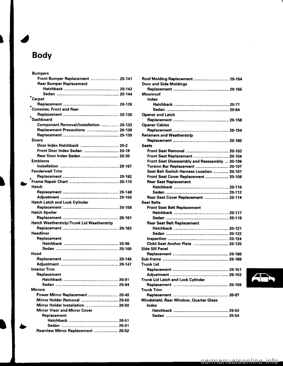
Body
Bumpers
Front Bumper Replacement ....................-..... 20-111
Rear Bumpar Replacemeni
Hatchback ................. 20-1/B
Sedan .................... ....20-111'Carpet
. Repfacemenl .,.,.,.,,..-....-.20-126
Consoles, Front and Rear
* Replacement ..................20-130
Dashboard
Component Removal/lnstallation ................ 20-133
Replacement Precautions ...........,................. 20-138
R€placement ....,.,...........20-139
Doors
Door Index Hatchback ................................... 20-2
Front Door Index Sedan .................,.,..,.,....,.. 20-18
Rear Door Index Sedan ........,.,........,.............. 20-30
Emblems
Installation .....................20-167
FenderwellTrim
+ Replacement., ................20.162
Fram€ Repair Chart .-..........20-170
Hatch
Replacoment .......,..........20-118
Adiustment .................... 20-150
Hatch Latch and Lock Cylinder
Replacement ..,.,..... ........ 20-158
Hstch Spoiler
Replacement ......... .......-.20.161
Hatch Weatherstrip/Trunk Lid Wsatherstrip
Replacement ..................20.163
Headliner
ReDlacement
Hatchbsck ,.,....,......,.. 20-98
Sedan .........................................................20-100
Hood
Replacsment ......... ......... 20.146
Adiustment ....................20-117
lnterior Trim
Reolacement
Hatchback ................. 20-91
Sedan .........................................................20-9,1
Mirrors
Power Mirror Reolacement ..........,................ 20-49
Mirrol Holder Removal ............................,..... 20.50
Mirror Holder Installation .............................. 20-50
Mirror Visor and Mirrot Covet
Replacement
Haichback ............20-51
Sedan .................................................... 20-51
Rearview Mirror Reolacement ..........-....-.-.... 20.52
Roof Molding Rep|acament ................................ 20.164
Door and Sid€ Moldings
Replacement .,..........,..... 20-165
Moonroot
lnd6x
Hatchback -................20-77
Sodan .........................................................20-8il
Opener and Latch
Replacement .......... ......,. 20-156
Opensr Cables
Replacamsnt .,.,...,.. ......., 20-154
Retainers and W€atherstrip
Replacement .................. 20-160
Seats
Front Seat Romoval ....................................... 20-103
Front Seat Replacement ...........................,.,.. 20-104
Front Soat Disassembly and Reassembly ...20-106
Torsion Bar ReDlacomant .....,...,......,.......,..,., 2O-1O7
Seat Eelt Switch Ha.ness Location ..,...,.,.,..,2O-1O7
Front Seat Cover Replacemont ..,....,..,..,.....,. 20-108
Rear Soat Roplscemont
Hatchback ................. 20.110
Sedan.........................................................20-112
R€al Seat Cover Replacomont ...................... 20-114
Seat Belts
Front Seat Beh Replacement
Hatchback..................20.117
Sedan20-r18
Rear S6at Bolt R€plac€ment
Hatchback .-......-.-......20-121
Sedan.......................-.-....-.-..........-.............20-122
fnspection ......-.-.,....-.-....20-121
Chifd Seat Anchor Plate ................................ 20-125
Side Sill Panol
Beplacom€nt .................. 20-166
Sub-frame ........................... 20.169
Trunk Lid
Replacement ......... ..,..,.,.20-151
Adiustmeni .................... 20-153
Trunk Lid Latch and Lock Cvlindot
Replac€ment ......... ......... 20-159
Trunk Trim
Replacement .,.,,.,........... 20-97
Windshield, Rear Window, Ouarter Glass
lndex
Hatchback ...........,,.20-53
!
S6dan ......................................................... 20.54
Page 818 of 1681
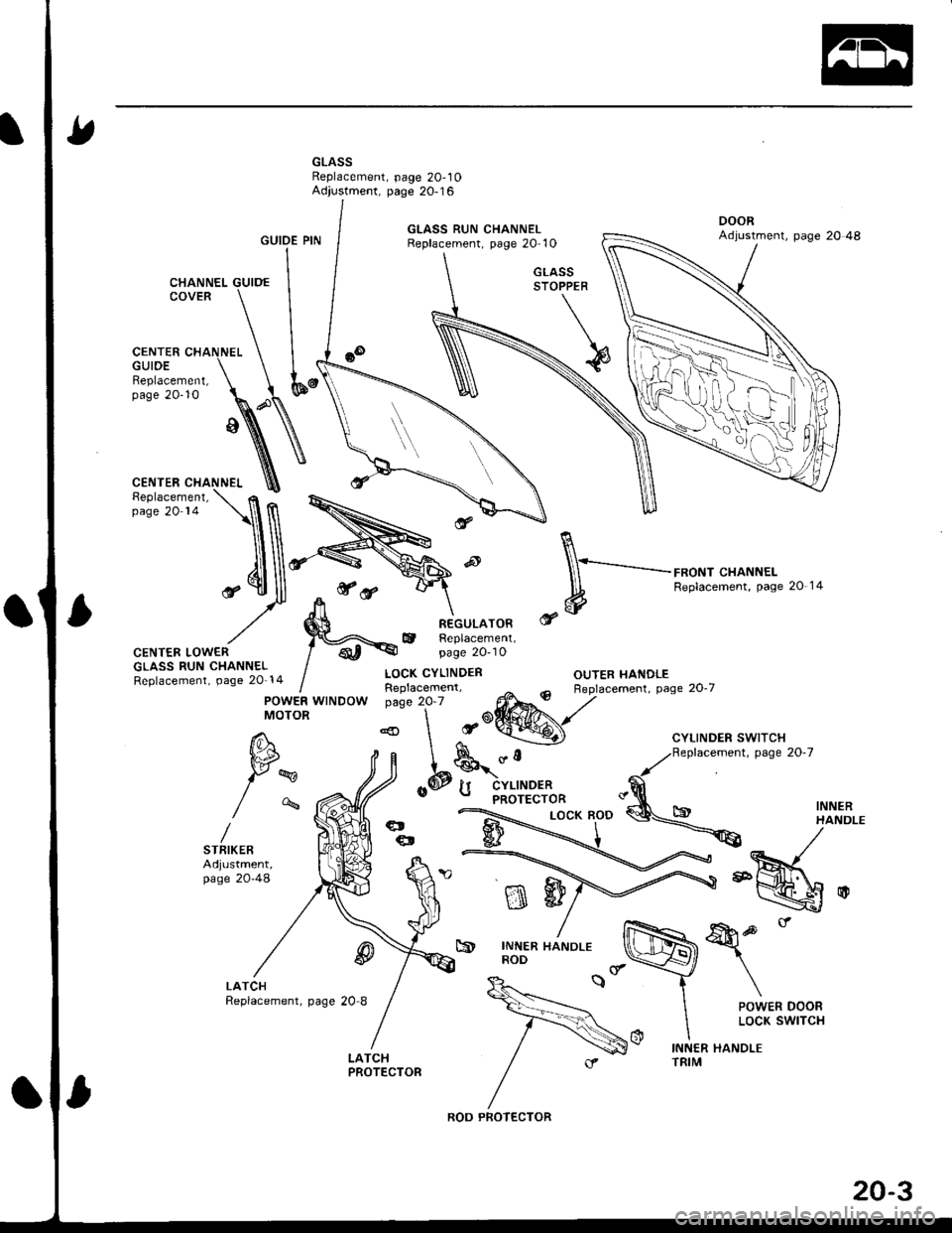
GLASSReplacement, page 20,10Adjustment, page 20-16
GUIDE PIN
CENTER CHANNELGUIDE
,**ry
R
\-_-..........-..-.-,*oNr .HANNEL
* #
Replacemenr. pase 20 14
OUTER HANDLE
mw
&p.'
\
POWER DOORLOCK SWITCH
c9INNER HANDLEROD
INNER HANDLETRIM
Replacement,page 20-10
CENTER LOWERGLASS RUN CHANNELReplacement, page 20-14
@
LOCK CYLINDER
REGULATORReplacement,page 2O-10
POWER WINDOWMOTOR
W
/-%
STFIKERAdjustment,page 20-48
@
ROD PROTECTOR
20-3
Page 823 of 1681
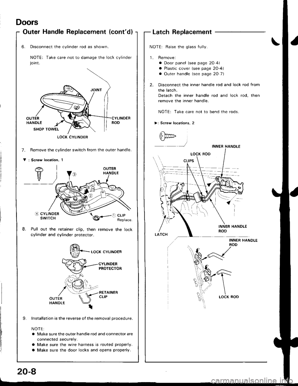
Doors
Outer Handle Replacement (cont'dlLatch Replacement
NOTEr Raise the glass fully.
'1. Remove:
a Door panel (see page 20 4)
a Plastic cover lsee page 20-4)
a Outer handle (see page 20 7)
2. Disconnect the inner handle rod and lock rod from
the latch.
Detach the inner handle rod and lock rod, then
remove the inner handle.
NOTE: Take care not to bend the rods.
>: Screw locations, 2
@t" ,
J
INNER HANDLEROD
INNER I{ANDLE
-1"'-
\
\LOCK ROD
)
INNER HANDLEROD
6.
8.
Disconnect the cylinder rod as shown.
NOTE: Take care not to damage the lock cylinder
joint.
OUTERHANDLECYLINDERROD
7.
V
SHOP TOWEL
Remove the cylinder switch lrom the outer handle.
: Scrsw location, 1
OUTERHANDLE
i4) cYLtNDERswtTcH
Pull out the retainer clip, then
cylinder and cylinder protector.
LOCK CYLINDER
li) clrPReplace
S*-.o"* .YLTNDER
CYLINDERPROTECTOR
RETAINERCLIP
Installation is the reverse of the removal procedure.
NOIE:
a Make sure the outer handle rod and connector are
connected securely.
a Make sure the wire harness is routed properly.
a Make sure the door locks and opens properly.
20-8
Page 824 of 1681
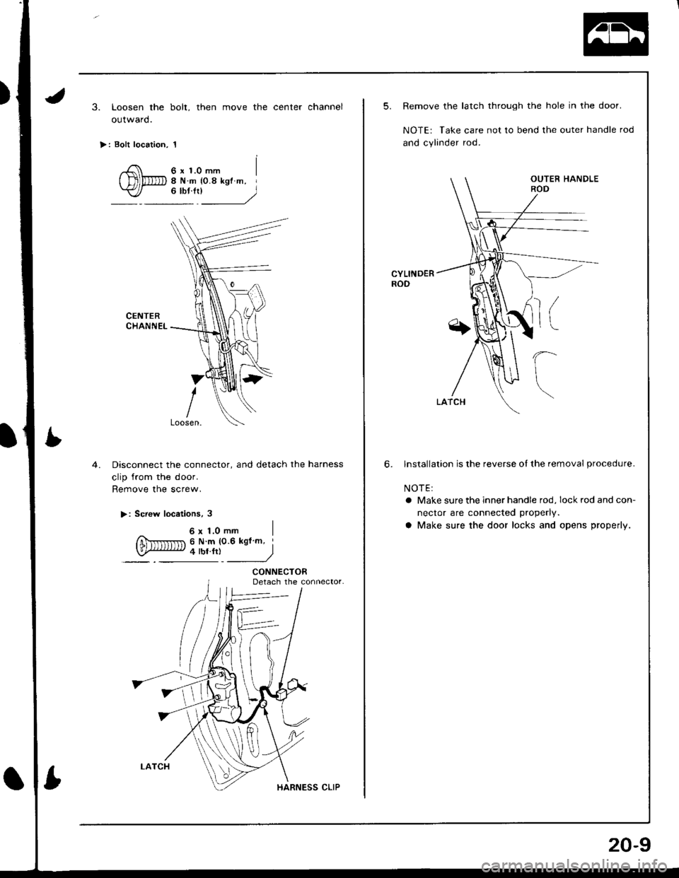
3. Loosen the bolt, then move the center channel
outward.
>: Bolt location, 1
6 x 1.0 mm8Nm {0.8kglm, I"*'l____)
CENTERCHANNEL
4.Disconnect the connector, and detach the harness
clip from the door.
Remove the screw,
>: Screw locations, 3
6x1.0mm IfiNrrlr
nr 6 N m (0.6 kgfm '
law iw.r,i )
CONNECTORDetach the connector.
5. Remove the latch through the hole in the door.
NOTE: Take care not to bend lhe outer handle rod
and cylinder rod.
CYLINDERROD
6. lnstallalion is the reverse of the removal procedure.
NOTEI
a Make sure the inner handle rod, lockrodandcon-
nector are connected properly.
a Make sure the door locks and opens properly.
20-9