HONDA INTEGRA 1998 4.G Workshop Manual
Manufacturer: HONDA, Model Year: 1998, Model line: INTEGRA, Model: HONDA INTEGRA 1998 4.GPages: 1681, PDF Size: 54.22 MB
Page 1381 of 1681
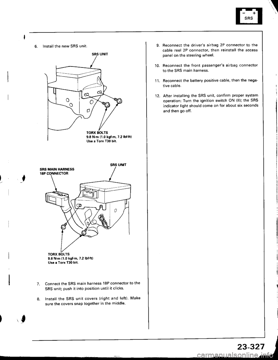
6, Install the new SRS unit.
o^ l- o
9.8 N.m 11.0 kgf m, 7.2Use a Torx T30 bit.
I
TORX BOLTS9.8 N.m 11.0 kgl.m, 7.2 lbf'ftlUse a Torx T30 bit.
7.Connect the SRS main harness l8P connector to the
SRS unit; push it into position until it clicks.
Install the SRS unit covers (right and left) Make
sure the covers snap together in the middle.8.
,l
\
10.
Reconnect the driver's airbag 2P connector to the
cable reel 2P connector, then reinstall the access
panel on the steering wheel.
Reconnect the front passenger's airbag connector
to the SRS main harness.
Reconnect the battery positive cable, then the nega-
tive cable.
After installing the SRS unit, confirm proper system
operation: Turn the ignition switch ON (ll); the SRS
indicator light should come on for about six seconds
and then go off.
11.
12.
Page 1382 of 1681

AEUl?A:
II'ITEGFIF|
trical Troubleshooting 98-OO
Page 1383 of 1681
).1
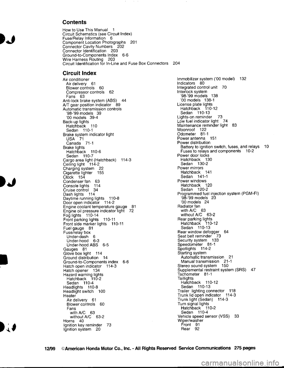
Contents
How to Use This l\.4anual 1Circuit Schematics (see Circuit Index)Fuse/Relaylnformation 6ComponentLocation Photographs 201
Connector Cavity Numbers 202Connectorldentification 203
Ground-to-Components Index 6-6Wire Harness Routing 203Circuit ldentification lor ln-Line and Fuse Box Connectors
Circuit Index
Air conditionerAir delivery 61Blower controls 60Compressor controls 62Fans 63Anti-lock brake system (ABS) 44A/T gear position indicator 89Automatic transmission controls'98199 models 39'00 models 39-4Back-up lightsHatchback 110Sedan 110- 1Brake system indicator light
USA 71Canada 71-1Brake lightsHatchback 110-6Sedan 110-7Cargo area light (Hatchback) 114-3Ceiling light 114-2Charging system 22Cigarette lighter 155
Clock 154Condenser fan 63Console lights 114Cruise control 34Dash lights 1 14Daytime running lights 110-8Door open indicator 114-2Engine coolant temperature gauge 81Engine oil pressure indicator light 72Fog lights 110-14Front parking lights 110-11Front side marker lights 110-11Fuel gauge 81Fuse/relay boxUnder-dash 6Under-hood 6-3Under-hood ABS 6-5Gauges 81Glove box light 114Ground distribution 14Ground-to-Componentsindex 6-6Hatch open indicator '114-3
Hatch opener '134
Hazard warning lightsHatchback 'l l0-2Sedan 110-4Headlights 1'10-8Headlight switch 100HeaterAir delivery 61Blower controls 60Fanswith A,/C 63without A,/C 63-2Horns 40lgnilion key reminder 73lgnition system 20
204
lmmobilizer system ('00 model) 132lndicators 80Integrated control unit 70Interlock system'98199 models 138'00 models 138-1License plate lightsHatchback 110-12Sedan 110-13Lights-on reminder 73Low fuel indicator light 74l\,4aintenance reminder light 83l\iloonroof 122Odometer 81-1Power antenna 151Power distributionBattery to ignilion switch, fuses, and relays
Fuses to relays and components 10-2Power door locksHatchback '130
Sedan 130-2Power mirrorsHatchback 141Sedan 141-1Power windowsHatchback 120Sedan 120-2Programmed fuel injection system (PGM-Fl)'98199 models 23'00 models 24Radiator fanwith tuC 63without A,/C 63-2Rear parking lightsHatchback 110-12Sedan 110- 13Rear window defogger 64Seat belt reminder 73Security system 133Speedometer Il-1Spotlights 114-2Starting syslemAutomalictransmission 21l\.4anualtransmission 21-1Stereo sound system 150Supplemental restraint system (SRS) 47Tachometer 81- 1TaillightsHatchback 110-12Sedan 110-13Trailer lighting conneclor 118Trunk lid open indicator 114-3Trunk light (Sedan) 114-3Turn signal lightsHatchback 110-2Sedan 110-4Vehicle speed sensor (VSS) 33Wiper/washerFront 91Rear 92
10
).1
I
Xr
12Fg oAmerican Honda Motor Co., Inc. - All Rights Reserved Service Communications 275 pages
Page 1384 of 1681
)
)
How To Use This Manual
The next few pages describe how this manual is organized. They also
exolain what kind of information the manual contains, what that
information means, and how to use it to troubleshoot electrical problems.
Circuit schemalics break the entire electrical system into individual
syslems, like the Low Fuel Indicator Light on the next page.
Only electrical components that work together are shown together,
so you won't be distracted by unrelated wires.
Explanations of the abbreviations and symbols used in the schematics
begin on page E. You'll need to know what they mean before you can use
a schematic effectively.
Page 1385 of 1681
How To Use This Manual
Circuit Schematics
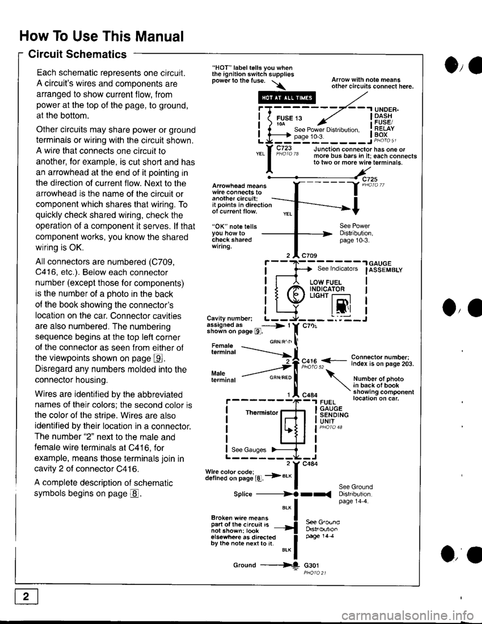
Each schematic reoresents one circuit.
A circuit's wires and components are
arranged to show current flow, from
power at the top of the page, to ground,
at the bottom.
Other circuits may share power or ground
terminals or wiring with the circuit shown.
A wire that connects one circuit to
another, lor example, is cut short and has
an arrowhead at the end of it pointing in
the direction of current flow. Next to the
arrowhead is the name ol the circuit or
component which shares that wiring. To
quickly check shared wiring, check the
operation of a component it serves. lf that
component works, you know the shared
wiring is OK.
All connectors are numbered (C709,
C416, etc.). Below each connector
number (except those for components)
is the number of a ohoto in the back
of the book showing the connector's
location on the car. Connector cavities
are also numbered. The numbering
sequence begins at the top left corner
of the connector as seen from eilher of
the viewpoints shown on page E.
Disregard any numbers molded into the
connector housing.
Wires are identif ied by the abbreviated
names of their colors; the second color is
the color of the stripe. Wires are also
identif ied by their location in a connector.
The number "2" next to the male and
female wire terminals at C416, for
example, means those terminals join in
cavity 2 of connector C41 6.
A complete description of schematic
symbols begins on page @.
O,e
Arowhead meanswire connects toanother ciacuit;it points in directionof current tlow.
"OK" note tellsYou how tocheck sharedwiring.
"HOT" label tells you whenthe ignition switch suppliesDower lo the fuse. \\
.---#
"*l
Broken wi.e means I
ffir"i:'ffi:[:l''" -{
elsewhere as directed Ioy ttt" not" n"n to [. u.* f
Ground ---{
Arrow with note meansother circuits connect here.
Distribution,page 10-3.
See lndicators
I
.| GAUGE
IASSEMBLY
I
I
I
IJO,'
i"?*i,h -..--.-{[
Cavity number; L--assigned as _----> 1shown on page l9l.
Maleterminal
c70!
F,":,2 f
- i":!f $l ?:T"'i,.i,.
Number ot photoin back ot bookshowing componentlocation on car.FUELGAUGESENDINGUNIT
See GroundDistribution.page 14'4.
c484
Thermistor
See Gauges
Splice ----------)f rr(
S€e GroundDstrb(rtlonpage 14 .l
G30t
iT;
Li=
- -.I UNDER-
FUsE 13 ../ I -Dl^s!io-a-- - , iFUsESee Power Drstlbulton. I RELAYpase 1o-3. ! Po^{^ -__:_____ ___Jp"otoa
o,a
Page 1386 of 1681
)o
)a
)wer IJrstnDullon Scnemallcs -
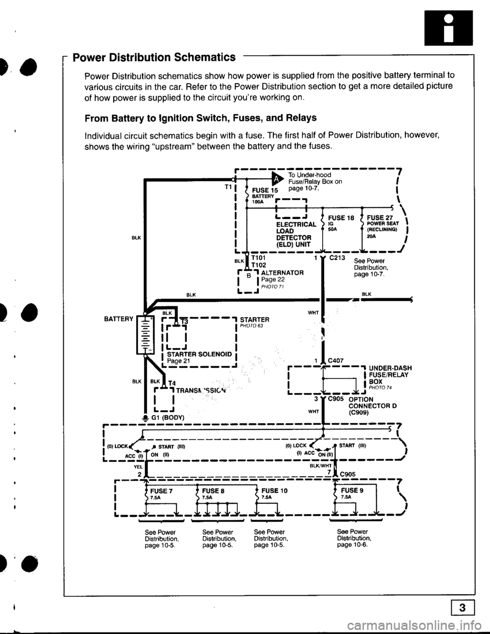
Power Distribution schematics show how power is supplied from the positive battery terminal to
various circuits in the car. Refer to the Power Distribution section to get a more detailed picture
of how power is supplied to the circuit you're working on.
From Battery to lgnition Switch, Fuses, and Relays
lndividual circuit schematics begin with a fuse. The first half of Power Distribution, however,
shows the wiring "upstream" between the battery and the f uses.
!' - - - -f -ro-unE,-"*l - - - - - - -
?---? i,"-")il"i"v-g& o" ,
FUSE 15 Page 10'7 1
hTt""r--.r \
TrL--J I ruse re I ruse zi/ ru:rE ro a .v-E., tELECTRTCAL ) rc ) PowER sEAr !iOA6".'-'- I * I (REcuNrNG) Igs-r-qqrg! | l'* I{ELD) Ul'{rLJ-------
*-lll3l 'f t"' l*.r:::f ;1 ALTERNAToR
tL_Jii1:"":
Distribuiion,pago 1G7.
SLK
BATTERYSTARTERBLK
4----t
tl
STARTER SOLENOID
I
I
+ G1 (BODY)
r
I
I
I
FUSE 1O754
Sge PowerDistribltion,page 10-5.
FUSE 97.tat
,
l---r+J
See Power Se€ PowerDistribution. Distribution.page 10-5. pag€ 10-5.
_l_
Sa€ PowerDistribution,page 10-6.
Power Distribution Schematics
tt
)o
Page 1387 of 1681
How To Use This Manual
Power Distribution Schematics
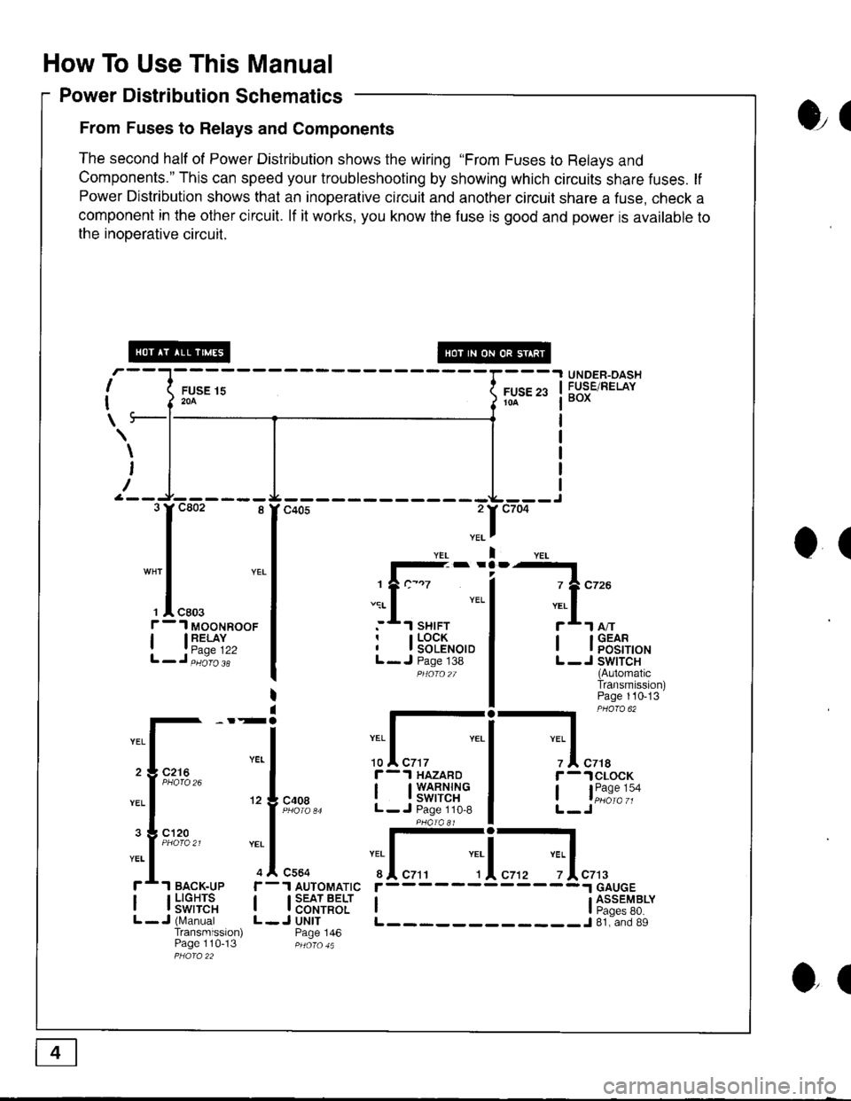
From Fuses to Relays and Components
The second half of Power Distribution shows the wiring "From Fuses to Relays and
Components." This can speed your troubleshooting by showing which circuits share fuses. lf
Power Distribution shows that an inoperative circuit and another circuit share a fuse, check a
component in the other circuit. lf it works, you know the fuse is good and power is available to
the inooerative circuil.
ol
I
I
\
FUSE 15204
UNDER-OASHFUSE/RELAYBOXFUSE 2310A
\
I
/
O(
.II
l-- -
1?c-.7
.:r- I YEL
:*.l sHrFTr I LOCKI I SOLENOIDL- J Page 138PHOfO2T
I lFEt[,o'
L -J SWITCH(AutomaticTransmission)Page 110-13
-l PHaro 62
IYEL Iz I czrar -.lclocK
, l"i1:"':oL-Jc408
r-.l HAZARD
I t3'�S[t''i"L- J Page 110,8
:I-c564
1 AUTOMATIC
I SEAT BELTI CONTROLJ UNITPage 146
YEI
r
IL
c7t3
I l5"f,TE'"L -J (N,4anualTransmission)Page 110-13
r------
I ti:*'"T8*L____________J 81. and 89
3rc802 8
I
"* | YEL
I
', I "ro.f - 1 MooNRooF
| 13"'^TI",L-J,iiio'i'
2 3 C216
3 g cl20
ol
Page 1388 of 1681
)a
)a
'ouno ulslnoulron Scnemarlcs -
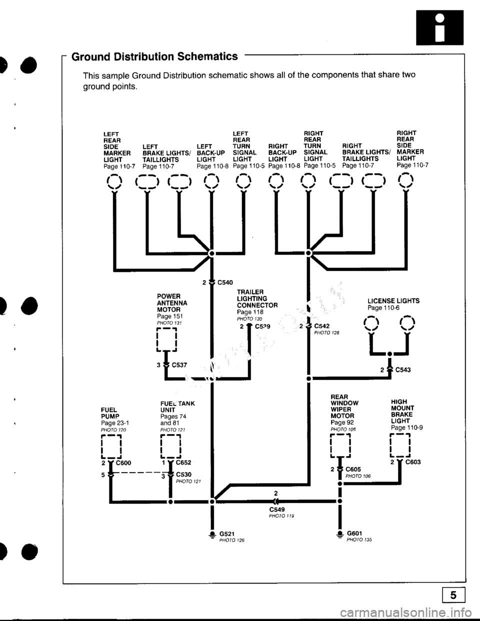
This samDle Ground Distribution schematic shows all of the components thal share two
ground points.
LEFT RIGHT RIGHTREAR REAR REARLEFT LEFT TURN RTGHT TURN RIGHT SIDEBRAKE LIGHTS/ BACK-UP SIGNAL BACK-UP SIGNAL BRAKE LIGHTS/ MARKER
TAILLTGHTS LIGHT LIGHT LIGHT LIGHT TAILLIGHTS LIGHT
Page110-7 Page110-8 Page110-5 Page110-8 Page110'5 Page110-7 Page110-7
r--r r--t t- t-l t-t ,-t r--r r--t r-\t*-r r--r \./ \/ \./ \/ \/
I LICENSE LIGHTS
I Page 110'6
l"uo, O O
l*"''* L.J
!-.1**
FUELPUMPPage 23-1
lltl
LEFTREARstoEMARKERLIGHTPage 110-7
POWERANTENNAMOTORPage 151
tlll
:E_,
a-al
JL
c549
t\
HIGHMOUNTBRAKELIGHTPage 110-9
ttll
REARwtNDowWIPERMOTORPage 92
tlll
iIn*
a-
Ira
T!. G601
FUEL TANKUNITPages 74and 81
tltl
1 Y C652
irg c530- | puoro tzt
I
106
T+ Gs21
c603
Ground DistributiSchematics
E
)o
Page 1389 of 1681
How To Use This Manual
Component Locations
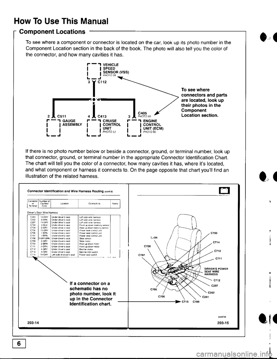
To see where a component or connector is located on the car, look up its photo number in the
Component Location section in the back of the book. The photo will also tell you the color of
the connector. and how manv cavities it has.
VEHICLESPEEDSENSOR (VSS)
ENGINECONTROLUNIT (ECMPHOIO 8A
0,, I
tl
tl
'r"'
To see where
connectors and parts
are located, look up
their photos in the
Component
Location section.
r -.I GAUGE
| | ASSEMBLY I
rtlL-J L-
r -'l
ll
ll
O,(
ot(
il"l,*.I CRUISE
I CoNTROL
i"u,t',:..
lf there is no photo number below or beside a connector, ground, or terminal number, look up
that connector, ground, or terminal number in the appropriate Connector ldentification Chart.
The chart will tell you the color of a connector, how many cavities it has, where it's located,
and what component or harness it connects to. On the page opposite that chart you'll find an
illustration of the related harness.
Connector ld6nlillcallon and Wire Harness Rouling tconrd)
SEAT WIFEHAFNESS
c712lf a connector on a
schematic has no
photo number, look it
up in the Connector
ldentification chart.
c297
203-15203-14
t-
Page 1390 of 1681
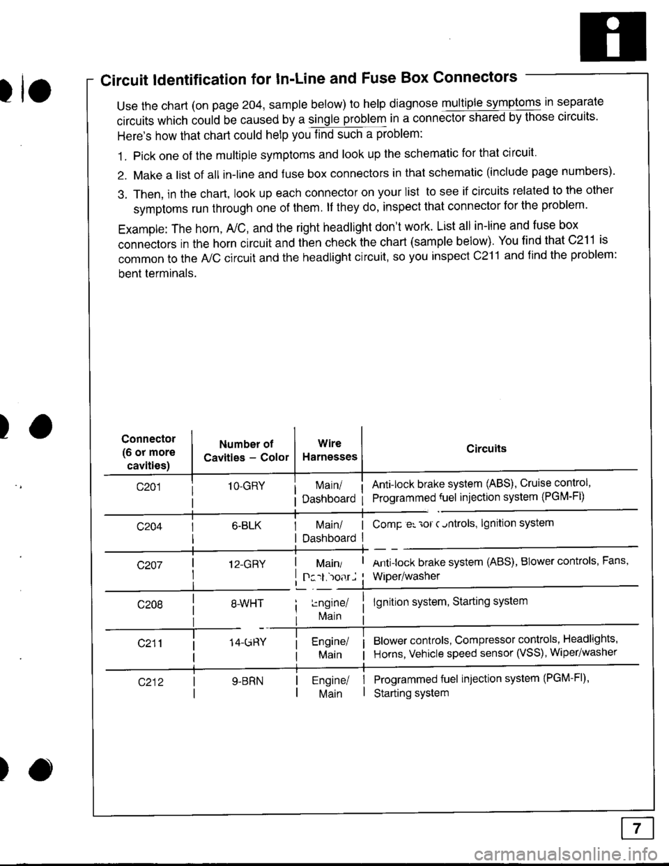
Circuit ldentification for In'Line and Fuse Box Connectors
tuse the chart (on page 204, sample below) to help diagnose multiple symptoms in separate
circuits which could be caused by a single problem in a connect,oishared by those circuits'
Here's how that chart could help you find such a problem:
1. Pick one of the multiple symptoms and look up the schematic for that circuit'
2. Make a list of all in-lrne and fuse box connectors in that schematic (include page numbers).
3. Then, in the chart, look up each connector on your list to see if circuits related to the other
symptoms run through one of them. lf they do, inspect that connector for the problem.
Example: The horn, A,/C, and the right headlight don't work. List all in-line and fuse box
connectors in the horn circuit and then check the chart (sample below). You find that C211 is
common to the A,/C circuit and the headlight circuit, so you inspect c211 and find the problem:
bent terminals.
)Connector
(6 or more
cavities)
Numbel of
Cavities - Color
1O-GRY
I 12-GRY
I
Wire
Harnesses
I Main/ | ComP er 'ror c.ntrols,
I Dashboard I
Circuits
Ant!lock brake system (ABS), Cruise control,
Programmed {uel injection system (PGM-FD
!ngrnei
lvlain
lgnition system
Antilock brake system (ABS), BIower controls, Fans,
Wiper/washer
lgnition system, Starting system
Blower controls, Compressor controls, Headlights'
Horns, Vehicle speed sensor (VSS), Wiper/washer
Programmed fuel injection system (PGM-Fl)'
Starting system
Engine/ |Main I
)