Mount HONDA INTEGRA 1998 4.G Workshop Manual
[x] Cancel search | Manufacturer: HONDA, Model Year: 1998, Model line: INTEGRA, Model: HONDA INTEGRA 1998 4.GPages: 1681, PDF Size: 54.22 MB
Page 43 of 1681
\-a
Engine Removal/lnstallation
Speciaf Tools .......... ...........5-2
Engine RemovaUlnstallation ................ 5-3
Mount/Bracket Torque .... 5-17
)
Page 48 of 1681
Engine Ramoval/lnstallation
(cont'dl
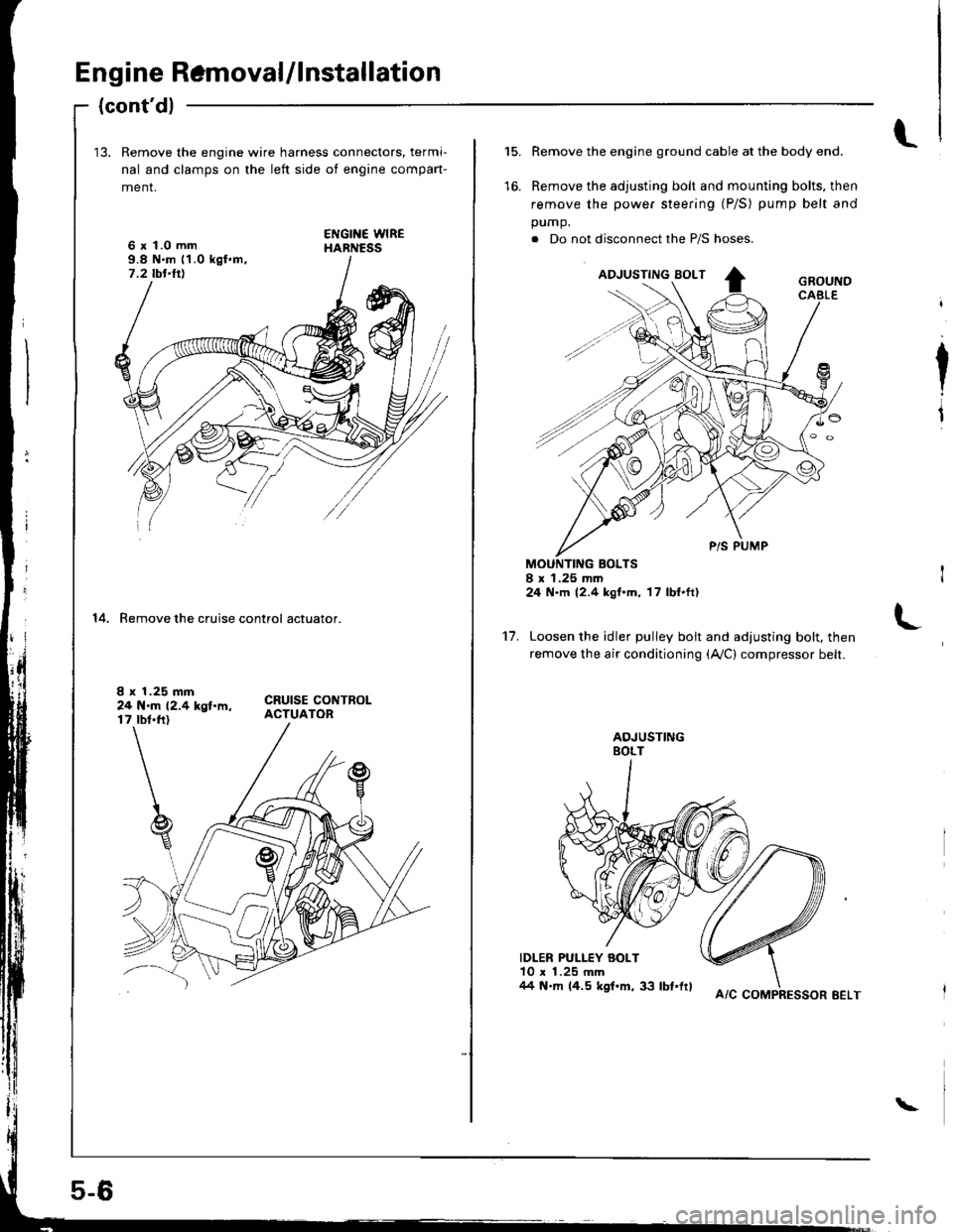
13. Remove the engine wire harness connectors, termi-
nal and clamps on the left side ot engine compan-
menr,
6 x 1.0 mm9.8 N.m 11.0 kgl.m,7.2 tbt.ttl
14. Remove the cruise control actuator.
I x 1.25 mm24 N.m 12.4 kgt.m,17 tbt.ft)
5-6
A/C COMPRESSOR EELT
\
l.15.
to.
Remove the engine ground cable at the body end.
Remove the adjusting bolt and mounting bolts, then
remove the power steering (P/S) pump belt and
pump.
. Do not disconnect the P/S hoses.
MOUNTING BOLTSI x 1.25 mm24 N.m 12.4 kgt'm, 17 lbl.ft)
Loosen the idler pulley bolt and adjusting bolt, then
remove the air conditioning (Ay'C) compressor belt.
IDLER PULLEY BOLT10 x 1.25 mm/14 N'm 14.5 kgf.m, 33 lbt'frl
I
I
't7.
Page 56 of 1681
Engine Removal/lnstallation
Engine lnstallation
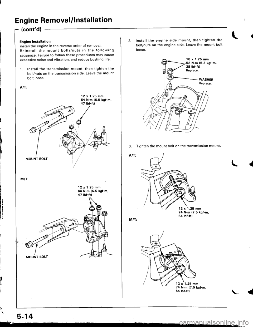
Installthe engine in the reverse order of removal
Reinstall the mount bolts/nuts in the following
sequence. Failure to follow these procedures may cause
excessive noise and vibration, and reduce bushing life
1. Install the transmission mount, then tighten the
bolvnuts on the tfansmlssion side. Leave the mount
bolt loose.
AIT:
'12 x 1.25 mmg N.m (6.5 kgl'm.
(cont'dl
5-14
47 thl.ftl
/o
llf
MOUNT EOLT
12 x 1.25 mm64 N.m {6.5 kgf.m,47 lbf.fr|
I
I
2. Install the engine side
bolvnuts on the engtne
toose.
M/T:
mo u nt, then tighten the
side. Leave the mount bolt
10 x 1.25 mm52 N.m 15.3 kgf.m,38 tbf.ft,Replace.
3, Tighten the mount bolt on the transmission mount.
AIf l
12 x 1.25 mm
L
\
{
74 N.m 17.5 kgl.m,54 rbf.ftl
12 x 1.25 mm74 N.m (7.5 kgl.m,54 rbf.ftl
Page 58 of 1681
Engine Removal/lnstallation
{cont'dl
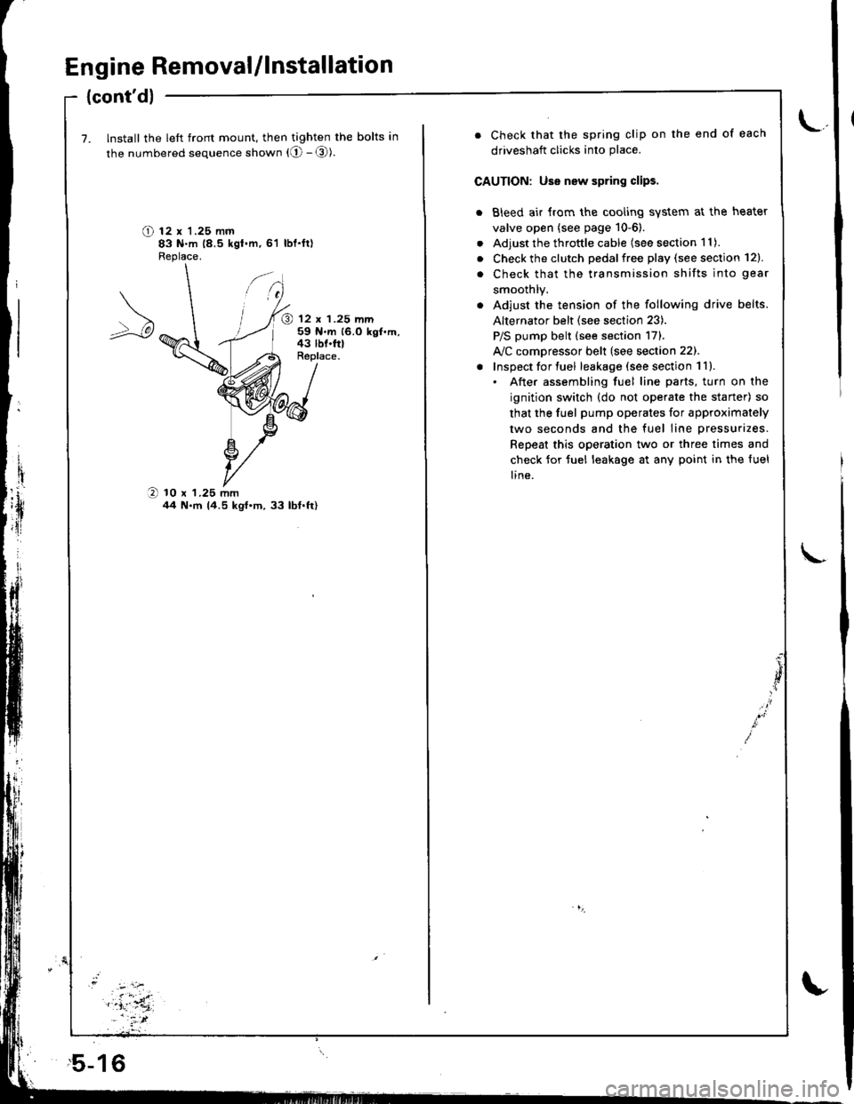
7. Install the left front mount, then tighten the bolts in
the numbered sequence shown (O - @).
O t2 x '1.25 mm83 N.m 18.5 kgt.m,61 lbl.ft)Fleplace.
@ 12 x 1.25 mm59 N.m 16.0 kgf.m,43 lbf.frlReplace.
O 10 x 1.25 mmil4 N.m 14.5 kgt'm,33 lbt.ft)
,5-16
. Check that the spring clip on the end of each
driveshaft clicks into place.
CAUTION: Use new spring clips.
. Bleed air {rom the cooling system at the heater
valve open (see page 10-6).
. Adjust the throttle cable (see section 1 1).
. Check the clutch pedalfree play (see section 12).
. Check that the transmission shifts into gear
smoothlY.
. Adjust the tension of the following drive belts.
Alternator belt {see section 23).
P/S pump belt (see section 171.
A/C comDressor belt (see section 22).
! Inspect for tuel leakage (see section 1ll.. After assembling fuel line parts, turn on the
ignition switch (do not operate the staner) so
that the fuel pump operates for approximately
two seconds and the fuel line pressurizes.
Repeat this operation two or three times and
check for tuel leakage at any point in the {uel
line.
Page 62 of 1681
I
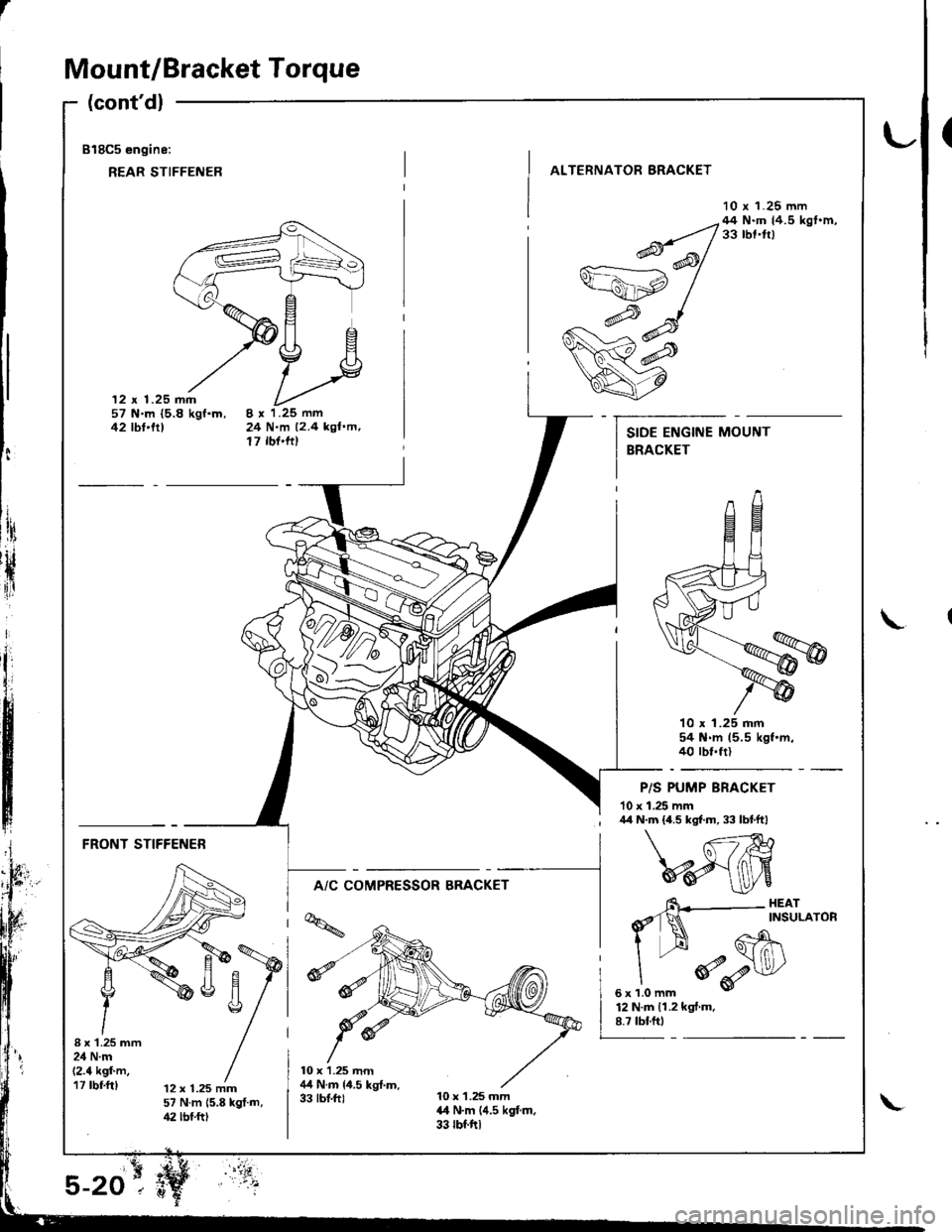
Mount/Bracket Torque
(cont'dl
818C5 engine:
REAR STIFFENER
(
ALTERNATOR BRACKET
10 r 1.25 mm
12 x 1.25 mm57 N.m {5.8 kgf.m,42 tbt'trt24 N.m 12.4 kgl.m,17 rbf'ftt
--q;;/44N'mtr.5kst'm'v=ahp /
w#
q7
10 x 1.25 mm54 N.m 15.5 kgf.m.40 rbt.frl
P/S PUMP BRACKET
10 x 1.25 mm
t:
ltri
rH
{ir
I\
; /r/r N.m {4.5 kgf.m, 33 lbtftl
FRONT STIFFENER
A/C COMPRESSOR BRACKET
I x'1.25 mm24 N.m(2.4 kgf'm,17 rbf.ft)12 x 1.25 mm57 N.m 15.8 kgt.m,42 lbf.ftt
6\--- HEAr
d'1N ^rNsuLAroR
I --H Gh\
"
*o-r$l/
sxrlomm v
12 N.m 11.2 kgf.m.8.7 tbf.ftt
Page 66 of 1681
Valve Clearance
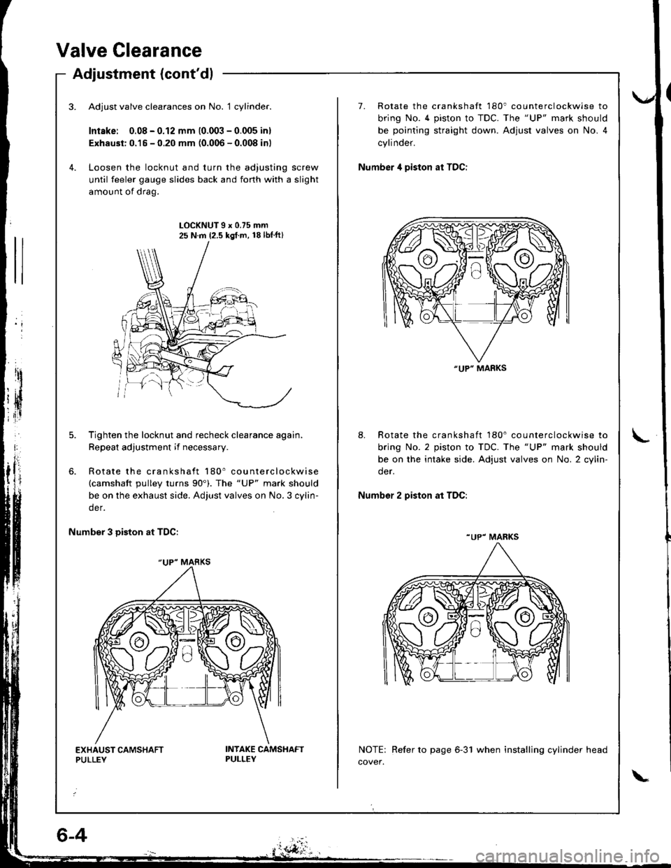
Adjustment (cont'dl
Adjust valve clearances on No. 1 cylinder.
Intske: 0.08 - 0.12 mm (0.003 - 0.005 inl
Exhaust: 0.15 - 0.20 mm (0.006 - 0.008 inl
Loosen the locknut and turn the adjusting screw
until feeler gauge slides back and forth with a slight
amount of drag.
7. Rotate the crankshaft 180' counterclockwise to
bring No. 4 piston to TDC. The "UP" mark should
be pointing straight down. Adjust valves on No. 4
cylinder.
Number 4 piston at TDC:
LOCKNUT9x0.75mm25 N.m {2.5 kgl.m, 18lbtft}
Tighten the locknut and recheck clearance again,
Repeat adjustment if necessary.
Rotate the crankshaft 180' counterclockwise(camshaft pulley turns 90'). The "UP" mark should
be on the exhaust side. Adjust valves on No,3 cylin-
der.
8. Rotate the crankshaft 180' counterclockwise to
bring No. 2 piston to TDC. The "UP" mark should
be on the intake side. Adjust valves on No. 2 cylin-
der.
Number 2 piston at TDC:
Number 3 Diston at TDC:
NOTE: Refer to page 6-31 when installing cylinder head
cover.
"UP" MARKS
"UP" MARKS
"UP" MARKS
Page 67 of 1681
Valve Seals
Replacement (cylinder head removal not required)
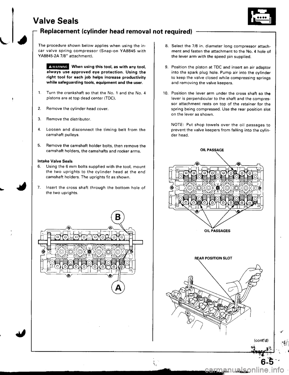
The procedure shown below applies when using the in-
car valve spring compressor (Snap-on YA8845 with
Y AAA45-2A 1 /8" attachment).
!@@ When using this tool, as with any tool,
always use approved eye protection. Using the
fight tool tor each job helps increase productivity
while safeguarding tools, equipment and ihe user.
Turn the crankshaft so that the No. 1 and the No. 4pistons are at top dead center (TDC).
Remove the cylinder head cover.
Remove the distributor.
Loosen and disconnect the timinq belt from the
camshaft oullevs.
5. Remove the camshaft holder bolts, then remove the
camshaft holders, the camshafts and rocker arms.
Intake Valve Seals
6. Using the 6 mm bolts supplied with the tool, mount
the two uprights to the cylinder head at the end
camshaft holders. The uprights fit as shown.
7. Insert the cross shaft through the bottom hole of
the two uprights.
8.
9.
10.
Select the 7/8 in. diameter long compressor attach-
ment and fasten the attachment to the No. 4 hole of
the lever arm with the speed pin supplied.
Position the piston at TDC and insen an air adaptor
into the spark plug hole. Pump air into the cylinder
to keep the valve closed while compressing springs
and removing the valve keepers.
Position the lever arm under the cross shaft so the
lever is perpendicular to the shaft and the compres-
sor attachment rests on top of the retainer for the
spring being compressed. Use the rear position slot
on the lever as shown.
NOTE: Put shop towels over the oil passages toprevent the valve keepers from falling into the cylin-
der head.
OIL PASSAGE
OIL PASSAGES
(cont'd),'.itil
i,
'6-b-'
Page 82 of 1681
Gylinder Head
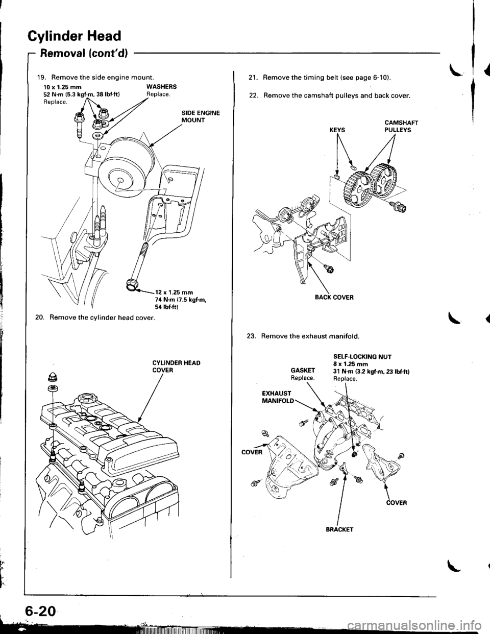
Removallcont'd)
19. Remove the side engine mount.
10 x 1.25 mm52 N.m {5.3 kgt:m, 38 lbl.ft}
20. Remove the cylinder head cover.
SIDE ENGINEMOUNT
12 x 1.25 mm74 N.m 17.5 kgt.m,sil lbtft)
CYLINOER HEADCOVER
t
L
I'
L21.
22.
Remove the timing belt (see page 6- 10).
Remove the camshaft pulleys and back cover.
CAMSHAFTPULLEYS
23. Remove the exhaust manifold.
GASKETReplace.
SELF.LOCKING NUT8 x 1.25 mm3'l N.m 13.2 kgl.m, 23 lbf.ftlReplace.
Page 182 of 1681
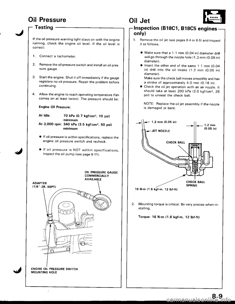
Oil Pressure
Testing
lf the oil pressure warning light stays on with the enginerunning, check the engine oil level. It the oil level iscorrect:
Connect a tachometer.
Remove the oil pressure switch and install an oil pressure gauge.
Start the engine. Shut it off immediately if the gaugeregasters no oil pressure. Repair the problem beforecontinuing.
Allow the engine to reach operating temperature (fan
comes on at least twicel. The pressure should be:
Engine Oil Pressure:
At ldle: 70 kPa {O.7 kgficmr, tO psil
minimum
At 3,OOO rpm: 34O kPa (3.5 kgf/cmr, 50 psil
minimum
a lf oilpressure is within specifications, replace theengine oil pressure switch and recheck.
a lf oil pressure is NOT within specifications,rnspect the oil pump (see page g-11).
l�
2.
Oil Jet
lnspection(818C1, 818C5 engines
only)
1. Remove the oil jet (see pages 8 4 or 8 5) and inspectit as follows.
a Make sure rhat a 1 .1 mm (O.04 in) diameter drillwillgo through the nozzle hole fl.2 mm (O.O5 in)diameter).
a Insert the other end of the same 1 .1 mm {0.O4in) drill into the oit intake (1.2 mm (0.05 in)diameter).
Make sure the check ball moves smoothly and hasa stroke of approximately 4.0 mm (O.16 in).a Check the oil jet operation with an air nozzle. ltshould take at least 2OO kPa 12.O kg|lcm2, 2gpsi) to unseat the check ball.
NOTE: Replace the oiljet assembly if the nozzleis damaged or bent.
2. Mounting torque is critical. Be very precise when in-stalling.
Torque: 16 N.m (1.6 kgf.m, 12 lbf.ftl
1.2 mm (0.05 inl
16 N.m {1.6 kgf'm, 12 lbf.ftl
8-9
Page 201 of 1681
8.Mix the recommended antifreeze with an equal
amount of water in a clean container.
NOTE:
a Use only genuine Honda antifreeze/coolant.
a For best corrosion protection, the coolant concen-
tration must be maintained year-round at 500,6
minimum. Coolant concentrations less than 507o
may not provide sufficient protection against cor,
rosion or freezing.
a Coolant concentrations greater than 60% will im-
pair cooling efliciency and are not recommended.
CAUTION:
a Do not mix different brands of anti-lrcezel
coolants.
a Do not use additional rust inhibitots or anti-tustproducts; they may not be compatible with the
coolant.
Engine Coolant Refill Capacity [including reservoir
{0.6 { (0.6 US qt, 0.5 lmp qr)ll:
81881 engine:
Ml7:1-1t {/t.6 US qt. 3.9 lmp qtl
818B1, 818C1 engin€s:
AlTt 1.7 | 15.0 US qt, 4.1 lmp qt)
818C1, B18C5 engines:
MlTt 1.7 t 15.0 US $, 4.1 lmp qtl
FILLER NECK
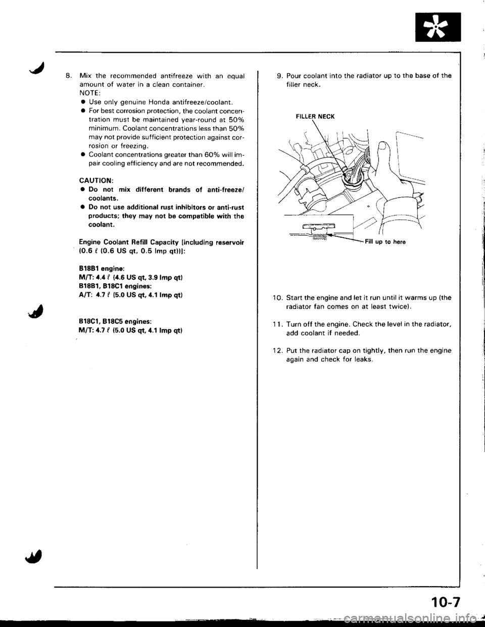
9.Pour coolant into the radiator up to the base of the
tiller neck.
10. Startthe engine and let jt run until itwarmsup(the
radiator fan comes on at least twice).
1 1 . Turn olf the engine. Check the level in the radiator,
add coolant if needed.
'12. Put the radiator cap on tightly, then run the engine
again and check for leaks.
10-7