Mount HONDA INTEGRA 1998 4.G Workshop Manual
[x] Cancel search | Manufacturer: HONDA, Model Year: 1998, Model line: INTEGRA, Model: HONDA INTEGRA 1998 4.GPages: 1681, PDF Size: 54.22 MB
Page 1340 of 1681
Precautions/Procedures
Steering-related Precautions
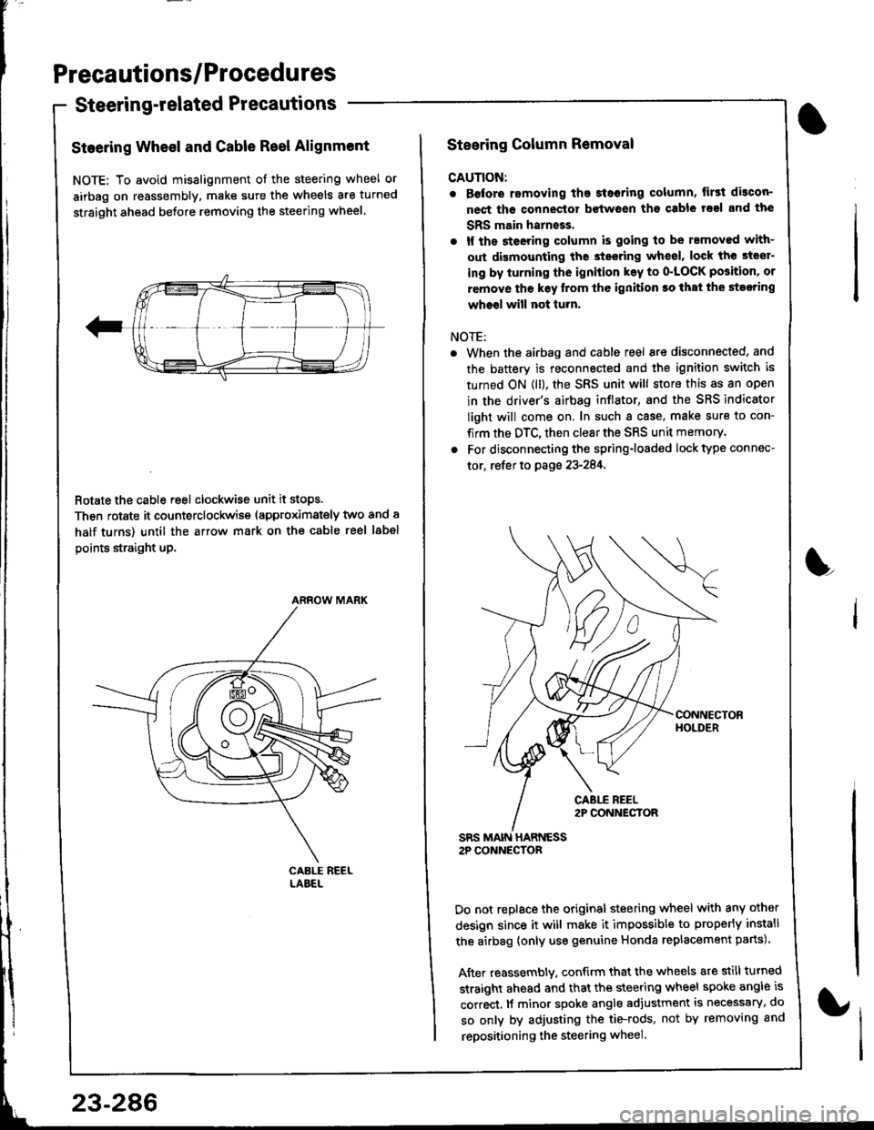
Steering Wheel and Gable Reel Alignment
NOTE: To avoid misalignment of the steering wheel or
airbag on reassembly. make sure the wheels are turned
straight ahead before removing the steering wheel.
Rotate the cable reel clockwise unit it stops.
Then rotate it counterclockwise (approximately two and a
half turns) until the arrow mark on the cable reel label
points straight up.
ARROW MARK
23-286
Steering Column Removal
CAUTION:
. Before romoving the steoring column, lirst di3con-
nect ths connector bctwoen tho csble rsal and the
SBS main harneEs.
. lf the steeting column is going to be rsmoved with-
out dismounting the steering wheel, lock the steer-
ing by iurning the ignition k6y to o'LOCK position' or
remove tho key lrom thc ignition ro that the steering
wheel will not turn.
NOTE:
When the airbag and cable reel are disconnected, and
the battery is reconnected and the ignition switch is
turned ON (ll), the SRS unit will store this as an open
in the driver's airbag inflator, and the SRS indicator
light will come on. In such a case, make sure to con-
firm the DTC, then clear the SRS unit memory.
For disconnecting the spring-loaded lock type connec-
tor, refer to page 23-284,
SRS MAIN HARNESS2P CONNECTOR
Do not replace the original steering wheel with any other
design since it will make it impossible to properly install
the airbag {only use genuine Honda replacement parts).
After reassembly. confirm that the wheels are still turned
straight ahead and that the steering wheel spoke angle is
correct, lf minor spoke angle adjustment is necessary, do
so only by adjusting the tie-rods, not by removing and
repositioning the steering wheel.
L
Page 1372 of 1681
Airbag
Replacement (cont'd)
LOWERMOUNTINGNUTS
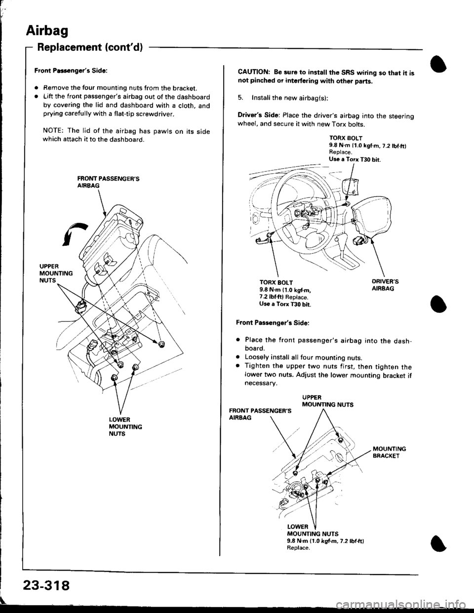
Fror|t P..s6nger'r Side:
. Remove the tour mounting nuts from the bracket.. Lift the front passenger's airbag out of the dashboard
by covering the lid and dashboard with a cloth. andprying carefully with a flat-tip screwdriver.
NOTE: The lid of the airbag has pawts on its sidewhich attach it to the dashboard.
CAUTION: Be sure to install the SRS wiring so that it isnot pincbed or interfering with other parts.
5. Install the new airbag(s):
Driver's Side: Place the driver's airbag into the steeringwheel. and secure it with new Torx bolts.
TORX BOLT9.8 N.m 11.0 kgf.m, 7.2 tbf.ft)
TORX BOLT9.8 N.m lt.o kgt m,7.2lbf,ftl Reptace.U36 a Torx T30 bit.
Front Paseenge/s Side:
Place the front passenger's airbag into the dash,bosrd.
Loosely install all four mounting nuts.Tighten the upper two nuts first, then tighten thelower two nuts. Adjust the lower mounting bracket ifnecessarv.
a
a
MOUNTING NUTS9.8 N.m (1.0 kgf.m. 7.2 lb{.ftlReplace.
Us€ a Torx T30 bit.
MOUNTING NUTS
Page 1374 of 1681
Before scrapping any airbags (including those in a whole
car ro be scrappedl, the airbags must be deployed. lf the
car is still within the warranty period, before you deploy
the airbags, the Acura District Technical Manager mustgive approval and/or special instructions. Only after theairbags have been deployed (as the result of vehicle colli-
sion, for example). can they be scrapped.
lf the airbags appear intact (not deployed). treat themwith extreme caution.
Follow this procedure:
Deploying the Airbags: In"vehicle
NOTE: lf an SRS vehicle is to be entirely scrapped. itsairbags should be deployed while still in the vehicle. Theairbags should not be considered as salvageable parts
and should never be installed in another vehicle.
E@ Contirm that each airbsg is securelymounted; otherwise, severe personal iniury could resultfrom deployment.
1. Disconnect the battery negative cable, then discon-nect the positive cable.
2. Confirm that the special tool is functioning properly
by following the check procedure on the label onthe tool or on page 23-321.
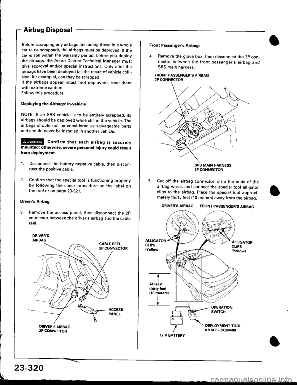
Driver's Airbag:
3. Remove the access panel, then disconnect the 2pconnector between the driver's airbag and the cablereel.
DRIVEE'SAIRBAGCABLE REEL2P CONNECTOR
Airbag Disposal
Oit,ER S AIREAG2P OdIIIECTOR
\\+- AccEss
I
PANEL
12 V EATTERY
Front Passenger's Airbag:
4. Remove the glove box, then disconnect the 2p con-nector between the front passenger's airbag andSRS main harness.
FRONT PASSENGER'S AIRBAG2P CONN€CTOR
SRS MAIN HARNESS2P CONNECTOR
5. Cut off the airbag connector, strip the ends ot theairbag wires. and connect the special tool alligatorclips to the airbag. Place the special tool approxi-mately thirty feet (10 meters) away from the airbag.
DRIVER'S AIRBAG FRONT PASSENGER'S AIRBAG
ALLIGATORCLIPSlYellowl
ALLIGATORCLIPSlYellowl
-T--
IAt leastthiny tcet110 meters)
IV
23-320
Page 1388 of 1681
)a
)a
'ouno ulslnoulron Scnemarlcs -
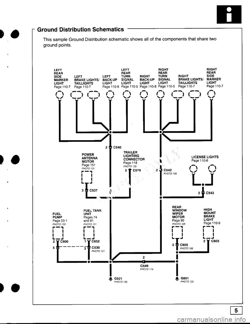
This samDle Ground Distribution schematic shows all of the components thal share two
ground points.
LEFT RIGHT RIGHTREAR REAR REARLEFT LEFT TURN RTGHT TURN RIGHT SIDEBRAKE LIGHTS/ BACK-UP SIGNAL BACK-UP SIGNAL BRAKE LIGHTS/ MARKER
TAILLTGHTS LIGHT LIGHT LIGHT LIGHT TAILLIGHTS LIGHT
Page110-7 Page110-8 Page110-5 Page110-8 Page110'5 Page110-7 Page110-7
r--r r--t t- t-l t-t ,-t r--r r--t r-\t*-r r--r \./ \/ \./ \/ \/
I LICENSE LIGHTS
I Page 110'6
l"uo, O O
l*"''* L.J
!-.1**
FUELPUMPPage 23-1
lltl
LEFTREARstoEMARKERLIGHTPage 110-7
POWERANTENNAMOTORPage 151
tlll
:E_,
a-al
JL
c549
t\
HIGHMOUNTBRAKELIGHTPage 110-9
ttll
REARwtNDowWIPERMOTORPage 92
tlll
iIn*
a-
Ira
T!. G601
FUEL TANKUNITPages 74and 81
tltl
1 Y C652
irg c530- | puoro tzt
I
106
T+ Gs21
c603
Ground DistributiSchematics
E
)o
Page 1406 of 1681
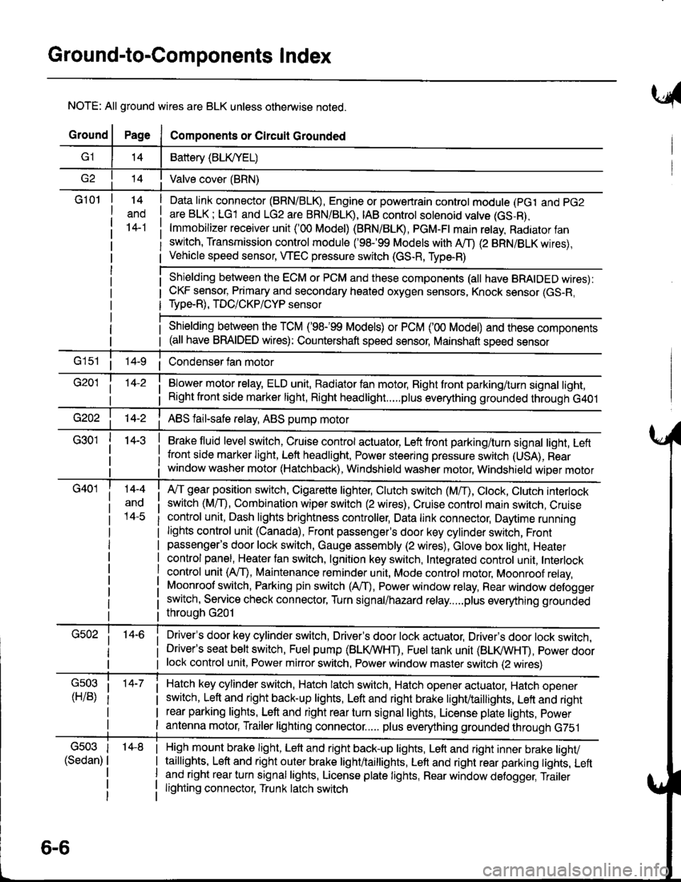
Ground-to-Components I ndex
NOTE: All ground wires are BLK unless otherwise noted.
GroundPageComponents or Circuit Grounded
Battery (BLIVYEL)
--t'I Valve cover (BRN)
G101t.+
and
14-1
Daia link connector (BRN/BLK), Engine or powertrain controt module (pct and pG2
are BLK; LG1 and LG2 are BRN/BLR, IAB controt solenoid valve (GS-B),
lmmobilizer receiver unit ('00 Model) (BRN/BLR, PGM-Ft main retay, Radiator fan
switch, Transmission control module ('98.�99 Models with MD (2 BRN/BLK wires),
Vehicle speed sensor, WEC pressure switch (GS-R, Type-R)
Shielding between the ECM or PCM and these components (all have BRAIDED wires):
CKF sensor, Primary and secondary heated oxygen sensors, Knock sensor (GS-R,
Type-R), TDC/CKP/CYP sensor
Shielding between the TCM ('98-'99 Models) or PCM ('00 Model) and these components(all have BRAIDED wires): Countershaft speed sensor, Mainshaft speed sensor
G1s1 ii Condenser fan motor
Brake fluid level switch, Cruise control actuator, Left front parking/turn signal light, Left
front side marker light, Left headlight, Power steering pressure switch (USA), Rear
window washer motor (Hatchback), Windshield washer motor, Windshield wiper motor
14-3
Blower motor relay, ELD unit, Badiator fan motor, Right front parking/turn signal light,
Right front side marker light, Right headlight.....plus everything grounded through G401
ABS fail-safe relay, ABS pump motor
G40114-4
ano
l4-c
A,/T gear position switch, Cigarette lighter, Clutch switch (M,/T), Ctock, Ctutch interlock
switch (MfD, Combination wiper switch (2 wires), Cruise control main switch, Cruise
control unit, Dash lights brightness controller, Data link connector, Daytime running
lights control unit (Canada), Front passenger's door key cylinder switch, Frontpassenger's door lock switch, Gauge assembly (2 wires), Glove box light, Heater
control panel, Heater tan switch, lgnition key switch, Integrated control unit, Interlock
control unit (AfI), Maintenance reminder unit, Mode control motor, Moonroof relay,
Moonroof switch, Parking pin switch (AfD, Power window relay, Rear window defogger
switch, Service check connector, Turn signal/hazard relay.....plus everything grounded
throuoh G201
Driver's door key cylinder switch, Driver's door lock actuator, Drivels door lock switch,Driver's seat belt switch, Fuel pump (BLI(/WHT), Fuel tank unit (BLI(/WHT), power doorlock control unit, Power mirror switch, Power window master switch (2 wires)
Hatch key cylinder switch, Hatch latch switch, Hatch opener actuator, Hatch ooener
switch, Left and right back-up lights, Left and right brake light/taillights, Lett and right
rear parking lights, Left and right rear turn signal lights, License plate lights, power
antenna motor, Trailer lighting connector..... plus everything grounded through G751
6-6
'14-8G503
(Sedan)
High mount brake light, Left and right back-up lights, Lett and right inner brake tighv
taillights, Left and right outer brake light/taittights, Left and right rear parking tights, Leftand right rear turn signal lights, License plate lights, Rear window detogger, Trailer
lighting connector, Trunk latch switch
Page 1407 of 1681
t-,O
i 14-7 i
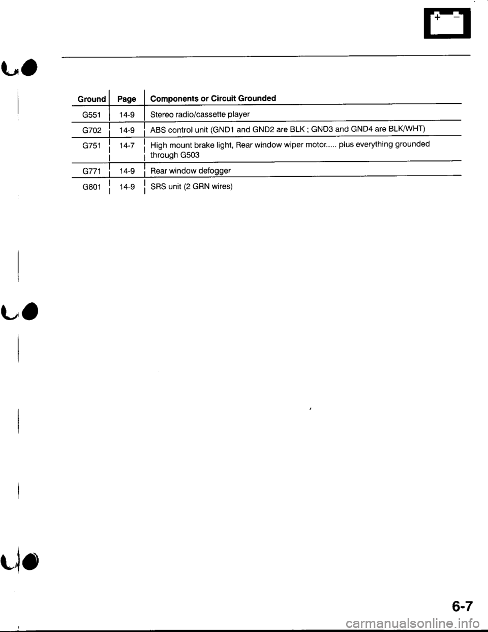
Components or Circuit Grounded
Stereo radio/cassette player
ABS control unit (GND1 and GND2 are BLK; GND3 and GND4 are BLKWHT)
High mount brake light, Rear window wiper motor..... plus everything grounded
through G503
i Rear window delogger
G801luslSRS unit (2 GRN wires)
UO
rio
6-7
Page 1426 of 1681
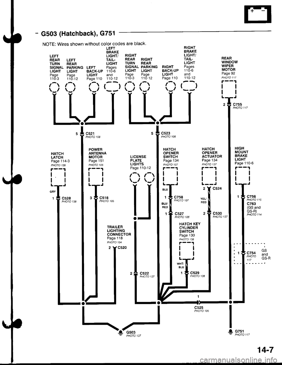
- G503 (Hatchback), G751
NOTE: Wires shown without color codes are black.
LEFT RIGHTBRAKE BRAKE
LEFT LIGHT/ RIGHT LIGHT/
REAR LEFT TAIL. REAB RIGHT TAIL-
TURN neln LIGHT TURN REAR LIGHT
SIGNAL PARKING LEFT Paqes SIGNAL PARKING RIGHT PAgCS
LIGHT LIGHT BAcK-uP 110-6 LIGHT LIGHT BACK.UP 110-6
Paqe Paoe LIGHT and Page Page LIGHT andtto*-s ttd-tz Paoe 110 110'12 110-3 110'12 Page 110 110-12
1-) 1- (-) r--r 1- 1-) f-) t--t(_r \_r \-/ r---' \-,, \-,, \.'/
LLIJ L-L.I
REARwtNDowWIPERMOTORPage 92
tl
PHOTO 108PHOTO 148
HATCHLATCHPage 114-3
t. I
lltl
cnv I
1 g c52a
HATCHOPENERSWITCHPage 134
HATCHOPENERACTUATORPage 134
HIGHMOUNTBRAKELIGHTPage 110'6
tl
tl
1 g c756
| ':::2"'
I (GS andI GS-R)
.l .rl' t- GS
: 'YF/o% :*^I a 1lz
I
IL
ALU
1
atu/
1
REO
c527PHOfO 106
HATCH KEYCYLINDERswtrcHPage 130
c530PHA|O 137
BLU
1c529
I
! cTsl
c525
POWERANTENNAMOTOR LICENSEPaoe 151 PLATEpu6rctos LIGHTS
|.--1 Page 110-12
| | l-t r-t
I | \-., \-,,
T;,. U
I iHi'$t"" I
I :3:.:ll: I
I ^ -:-"^ I
tt*l
tll
I I
'�l e:3?.,,,
ltl-ll-
14-7
Page 1427 of 1681
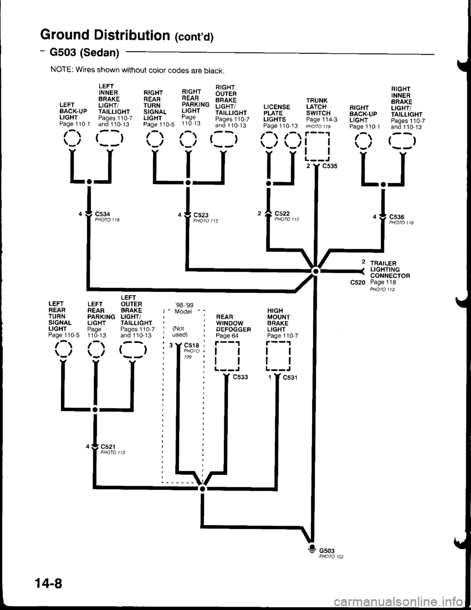
Ground Distributioh (cont'd)
- G503 (Sedan)
NOTE: Wkes shown without color codes are black.
LEFTIN NERBRAKELEFT LIGHT/BACK-UP TAILLIGHTLIGHT Paqes 110-7Paqe 110,1 and 110-13
r-,r ,--r\_,, r- -,
c534
L.JLIJL.J
TRAILERLIGHTINGCONNECTORPage 118
RIGHTINNERBRAKELIGHT/TAILLIGHTPages 110-7and 110-13
()
RrcHr l!-c.{r !'rqlt-
!iTfi^. iff#"" iilt[i",
b:::1,0. ii3:3 :i3::lts'
(:) (:) rllr
TRUNKLATCHswtTcHPage 114-3
tl
tl
2 Y C535
RIGHTBACK-UPLIGHTPage 110 1
/\
LEFTREARTURNSIGNALLIGHTPage 110-5
LEFTREARPARKINGLIGHTPage110-13
/\
LEFTOUTERBRAKELIGHT/TAILLIGHTPages 1'10-7and 110-13
()
'98-'�99
Model
(Notuseo)
cs22
HIGHMOUNTBRAKELIGHTPage 110-7
tl
REARwrNDowDEFOGGERPage 64
ll
14-8
Page 1494 of 1681
- How the Circuit Works
Do not smoke while working on the fuel system.
Keep open flame away from the work area. Drain
fuel only into an approved container.
A thermistor is mounted in the fuel tank unit. When
the thermistor is cool, its resistance is very high.
When the thermistor is warm, its resistance
decreases. Fuel in the fuel tank transfers heat away
from the thermislor last enough to keep it cool so
the thermistor's resistance stays high and the low
fuel indicator lighl does not come on. When the fuel
level drops below about 2.2 gallons, the thermistor
is no longer immersed in fuel. Without the fuel to
cool it, the thermistor's resistance decreases,
allowing current to flow through the low fuel
indicator light and the thermistor to ground, and lhe
low fuel indicator light comes on.
Refer to the Service Manual (Section 23, Electrical)
for specific tests or troubleshooting procedures.
74-1
Page 1519 of 1681
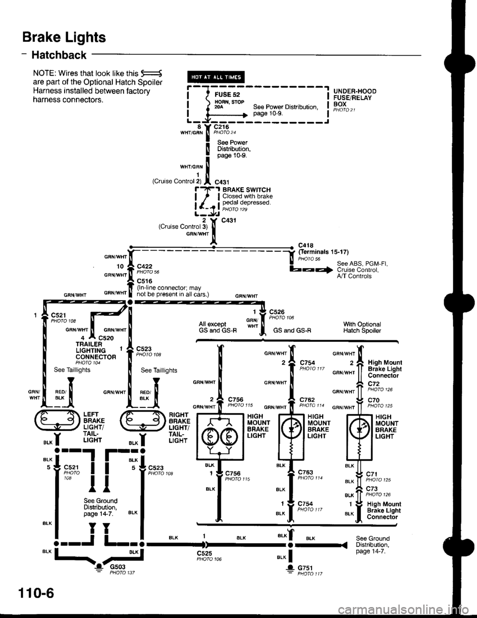
Brake Lights
- Hatchback
c521
NOTE: Wires that look like this q-
are part of the optional Hatch spoiler
Harness installed between factory
harness connectors.See Power Distribution,page 10-9.
UNDER-HOODFUSE/RELAYBOX
r-F-.t BRAKE SWTTCH
| ,, I Closed.wth brake
!'J3l 9ji'i ""0.""'"o
2 Y C431(Cruise Control3) llGRTTAIi'HT
Ic418-i fierminals 15-17)N PHOIO 56! See ABS, PGM-FI,b-Q ciu iie-c-6 nt'oi,A/T Controls
GRN/ryVHTGRNAI/HT
All exceptGS aod GS-F
c526
GS and GS-R
'|
GFN/With OptionalHatch Spoiler
c523
GRN/
See Taillights
d
See Taillights
4
o""a", 'il
z I xigrr uount2 ,l Hrgh Mounl
,- ll Brake Lighi'' ll ConnectorGRN^!/HT ll atn;;i;;
c72
GANAVHT
GFNA!/HT
GFNAVHT
c754
c762
-l H|GH I MOUiII BRAK. I LIGHI
J
c753
c754
GRNAVHl
GFNAI/HT
1-
-tt'I
BLK
BLK
1
BLK
'-'I
r-";
9i.1" I I 5
1a8
ll
See GroundDistribdion,Page 1,1-7. 8LK
TY
--J L--
cnr^rnr ff iioio 'zo
o""-"rfi 9'1%'"
llFl xrcnl/ 1.,\l MoUNT
lwli,Htl'
til
"i-fr s*,,.
":0 ?i:::: .
LEFTBRAKELIGHT/TAIL.LIGHT
RIGHTBRAKELIGHT/TAIL-LIGHT
c756
c756
MOUNTHIGHMOUNTBRAKELIGHT
i4TO 117
BLK
c523
1 V High Mount
JIBrake LightConnector
".*f
-.-<
u.* |
Jl c751
See GroundDistribution,page '14-7.*"1--./-.::I1
- PHOTO 1i7
c525
o"nn,"r'l(-- -
""J:,iiqf '
GRNA!/HT N GFNAIVHT
4 A C520
110-6