Mount HONDA INTEGRA 1998 4.G Workshop Manual
[x] Cancel search | Manufacturer: HONDA, Model Year: 1998, Model line: INTEGRA, Model: HONDA INTEGRA 1998 4.GPages: 1681, PDF Size: 54.22 MB
Page 1243 of 1681
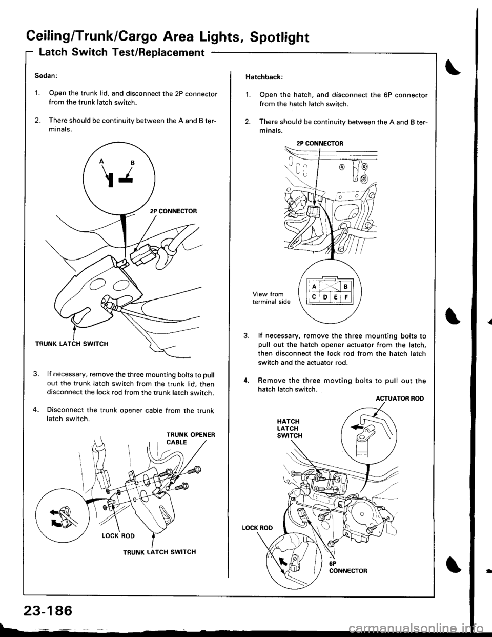
Ceiling/Trunk/Cargo Area Lights, Spotlight
Latch Switch Test/Replacement
Sedan:
1. Open the trunk lid. and disconnect the 2p connectorfrom the trunk latch switch.
2. There should be continuity between the A and B ter-
mtnats.
TRUNK LA
lf necessary, remove the three mounting bolts to pull
out the trunk latch switch from the trunk lid, thendisconnect the lock rod from the trunk latch switch.
Disconnect the trunk opener cable from the truoklatch switch.
OO
TRUNK LATCH SWITCH
23-146
Hatchback:
1. Open the hatch, and disconnect the 6P connector
from the hatch latch switch.
2. There should be continuity between the A and B ter-
minals.
lf necessary, remove the three mounting bolts topull out the hatch opener actuator from the latch,
then disconnect the lock rod from the hatch latch
switch and the actuator rod.
Remove the three movting bolts to pull out the
hatch latch switch.
ACTUATOR ROD
2P CONNECTOR
Page 1247 of 1681
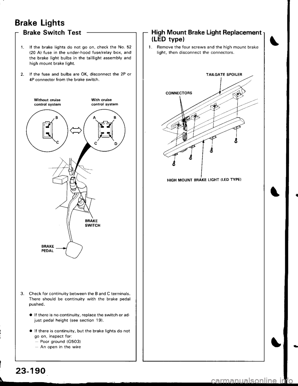
Brake
Brake
Lights
Switch TestHigh Mount Brake Light Replacement
\
t
2.
t.
3.
lf the brake lights do not go on. check the No. 52
{20 A) fuse in the under-hood fuse/relay box, and
the brake light bulbs in the taillight assembly and
high mount brake light.
lf the fuse and bulbs are OK, disconnect the 2P or
4P connector from the brake switch.
Without c.uisecontrol syst€mWilh cruisecontrol sYstem
Check for continuity between the B and C terminals.
There should be continuity with the brake pedal
pusneo.
a lf there is no continuity, replace the switch or ad-just pedal height (see section '19).
o It there is continuity, but the brake lights do not
go on, inspect for:
Poor ground (G5O3)
An open in the wire
AB
FS-A
lt--Ltl, t!,Z-\CD
-/Branl-ltl
tLatl\c
(LED typel
1. Remove the tour screws and the high mount brake
light, then disconnect the connectors.
TAILGATE SPOILER
HIGH MOUNT BRAKE LIGHT {tED TYPE}
23-190
Page 1248 of 1681
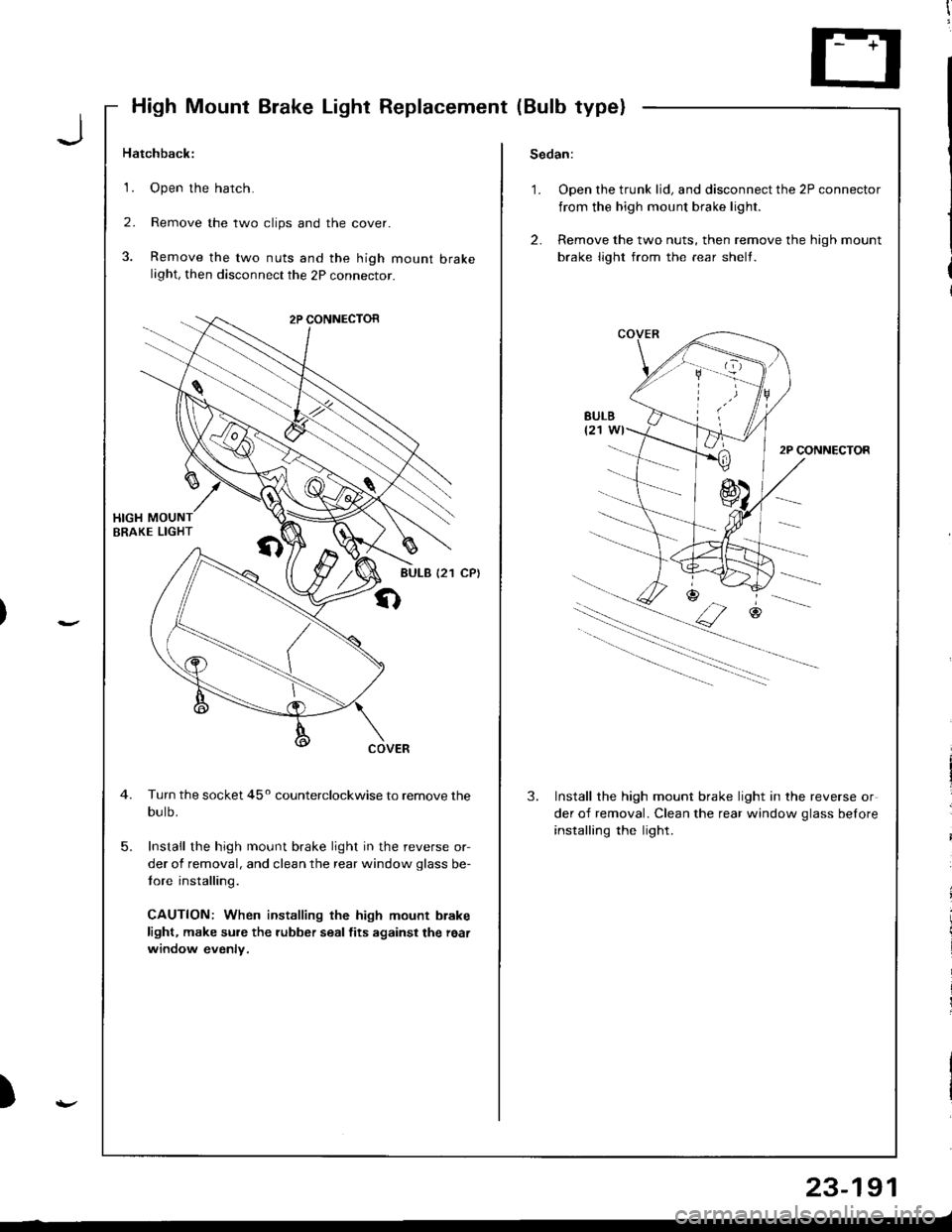
High Mount Brake Light Replacement (Bulb type)
Hatchback:Sedan:
1.Open the hatch.
Remove the two clips and the cover.
Remove the two nuts and the high mount brakelight, then disconnect the 2P connecror.
1.Open the trunk lid, and disconnect the 2P connector
from the high mount brake light.
Remove the two nuts, then remove the high mount
brake light from the rear shelt.
2.
3.
2.
2P CONNECTOR
Turn the socket 45o counterclockwise to remove the
bulb.
Install the high mount brake light in the reverse or-
der of removal, and clean the rear window glass be-
tore installing.
CAUTION: When installing the high mount brake
light, make sure the rubber seal fits against the reai
window evenly.
3.Install the high mount brake light in the reverse or
der of removal. Clean the rear window qlass belore
installing the light.
5.
)
23-191
Page 1256 of 1681
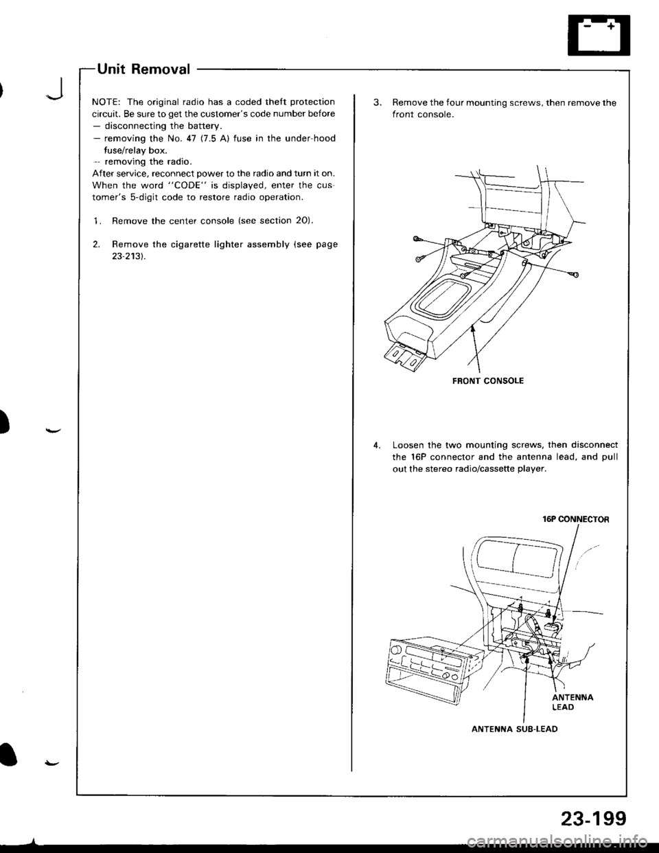
Unit Removal
NOTE: The original radio has a coded thelt protection
circuit. Be sure to get the customer's code number before- disconnecting the battery.- removing the No. 47 (7.5 A) fuse in the under-hood
fuse/relay box.- removing the radio.
After service. reconnect power to the radio and turn it on.
When the word "CODE" is displayed, enter the cus-
tomer's 5-digit code to restore radio operation.
'1. Remove the center console (see section 20).
2. Remove the cigarette lighter assembly (see page
23-2131.
)
FRONT CONSOLE
Remove the four mounting screws, then remove the
front console.
Loosen the two mounting screws. then disconnect
the 16P connector and the antenna lead, and Dull
out the stereo radio/cassette plaver.
16P CONNECTOR
ANTENNA SUB-LEAD
23-199
Page 1268 of 1681
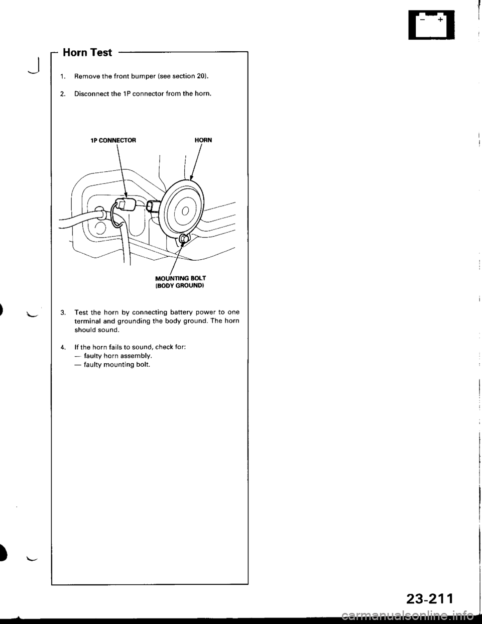
Horn Test
1.Remove the front bumper (see section 20).
Disconnect the 1P connector from the horn.
lP CONNECTOR
MOUNNNG BOLT
IBODY GROUND}
Test the horn by connecting battery power to one
terminal and grounding the body ground. The horn
should sound.
lf the horn fails to sound, check tor:- taulty horn assembly.- faulty mounting bolt.
J
Page 1270 of 1681
J
)
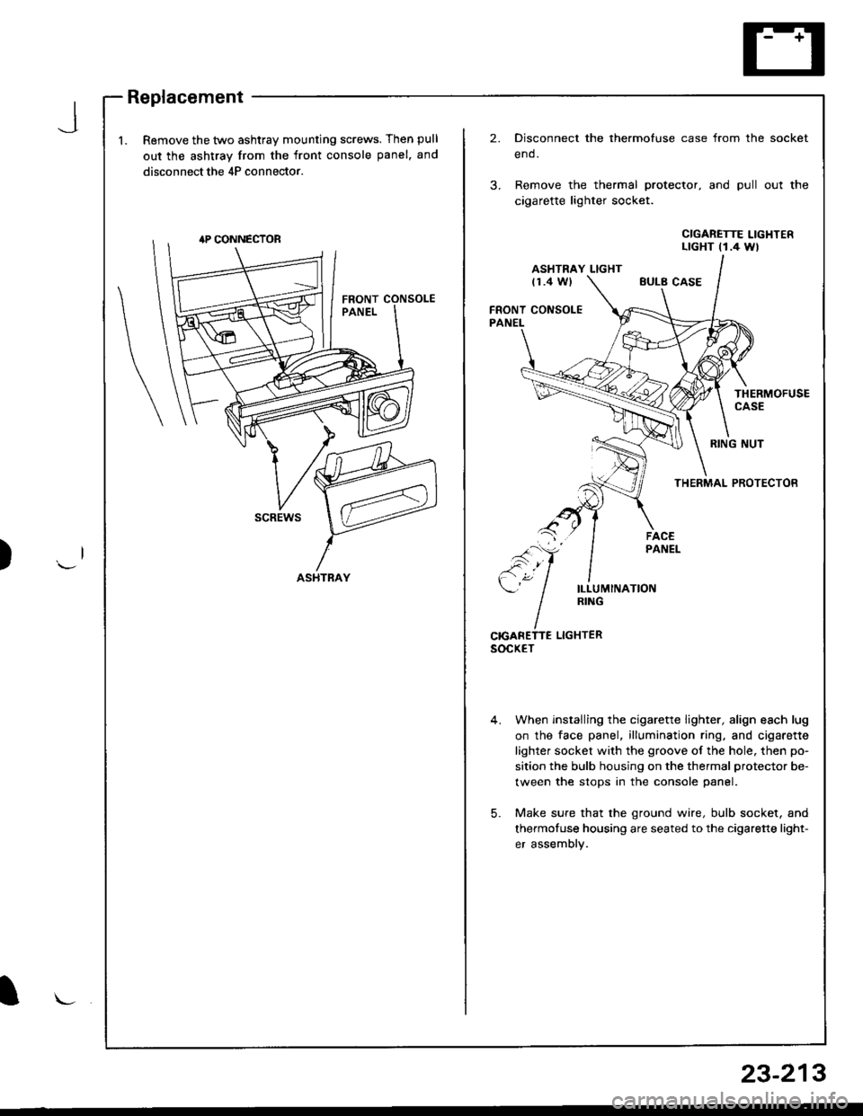
1.Remove the two ashtray mounting screws. Then pull
out the ashtray from the front console panel. and
disconnect the 4P connector.
2.Disconnect the thermofuse case from the
end.
Remove the thermal protector, and pull
cigarette lighter socket.
socket
out the
CIGARETTE LIGHTERLTGHT t1.4 Wl
ASHTRAY LIGHTt1.4 WlEULB CASE
FRONT CONSOLEPANEL
THERMOFUSECASE
RING NUT
THERMAL PROTECTOR
scREws
ILLUMINATIONRING
CrcANETTE LIGHTERsocxET
When installing the cigarette lighter, align each lug
on the face panel, illumination ring, and cigarette
lighter socket with the groove of the hole. then po-
sition the bulb housing on the thermal protector be-
tween the stops in the console panel.
Make sure that the ground wire, bulb socket, and
thermofuse housing are seated to the cigarette light-
er assembly.
5.
ASHTRAY
l\-
23-213
Page 1294 of 1681
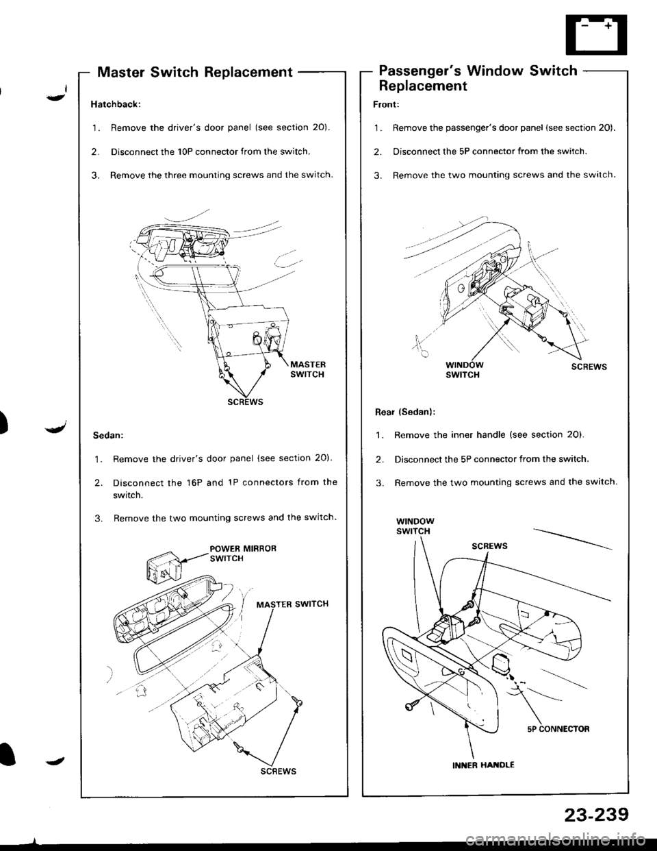
Hatchback:
1. Remove the driver's door panel (see section 20).
2. Disconnecl the 10P connector from the switch.
3. Remove the three mounting screws and the switch.
Sedan:
1. Remove the driver's door panel (see section 20).
2. Disconnect the 16P and 1P connectors from the
swrtcn.
3. Remove the two mounting screws and the switch.
POWER MIRRORswtrcH
scBEws
Master Switch ReplacementPassenger's Window Switch
I-
.J)
I
Replacement
Front:
1 . Remove the passenger's door panel lsee section 20).
2. Disconnect the 5P connector from the switch.
3. Remove the two mounting screws and the switch.
Rear (Sedan);
1. Remove the inner handle (see section 2O).
2. Disconnect the 5P connector from the switch.
3. Remove the two mounting screws and the switch.
wtNDowswrTcH
swtTcH
5P CONNECTOR
IN ER HATOLE
23-239
Page 1307 of 1681
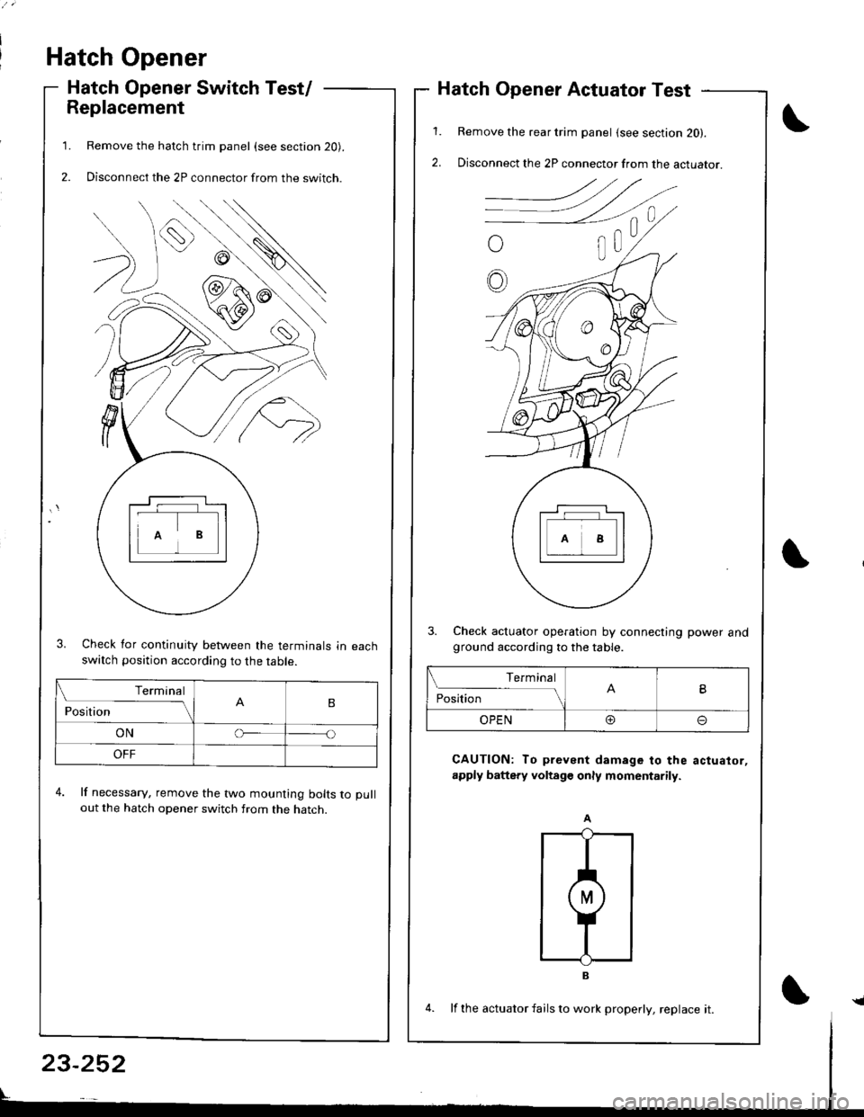
Hatch Opener
Hatch Opener Switch Test/
Replacement
Remove the hatch trim panel (see section 20).
Disconnect the 2P connector from the switch.
3. Check for continuity between the terminals in eachswatch position according to the table.
4. lf necessary, remove the two mounting bolts to pull
out the hatch opener switch from the hatch.
1.
2.
1.
2.
Hatch Opener Actuator Test
Remove the rear trim panel (see section 20).
Disconnect the 2P connector from the actuator.
3. Check actuator operation by connecting power andground according to the table.
CAUTION: To prevent damage to the actuator,
apply battery voltage only momentarily.
Terminal
PositionB
ONo
OFF
Terminal
PositionB
OPEN@o
23-252
4. lf the actuator fails to work properly, replace it.{
Page 1329 of 1681
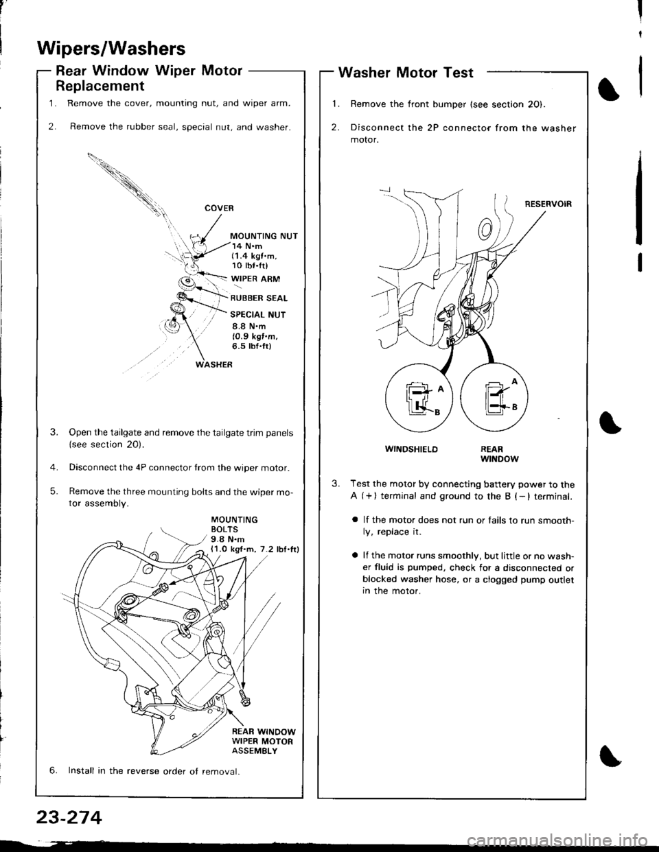
1.
2.
Replacement
Remove the cover, mounting nut, and wiper arm.
Remove the rubber seal, special nut, and washer.
COVEB
MOUNTING NUT
WASHER
14 N'm(1.4 kgt.m,10 tbf.tr)
WIPER ARM
RUBBER SEAL
SPECIAL NUT
8.8 N.m
10.9 kgf.m.6.5 tbf'fr)
MOUNTINGBOLTS9.8 N.m11.0 kgl.m, 7.2 lbl.lrl
REAR WINOOWWIPER MOTORASSEMELY
3.Open the tailgate and remove the tailgate trim panels
{see section 20).
Disconnect the 4P connector trom the wiper motor.
Remove the three mounting bolts and the wiper mo-
tor assembly.
5.
6. Install in the reverse order ot removal.
,'II
t
Wipers/Washers
Rear Window Wiper MotorWasher Motor Test
l�
2.
Remove the front bumper (see section 20).
Disconnect the 2P connector from the washer
motor.
RESERVOIR
1
WINDSHIELDREARwtNDow
3.Test the motor by connecting battery power to the
A (+) terminal and ground to the B (-lterminal.
a lf the motor does not run or fails to run smooth-
ly, replace it.
a lf the motor runs smoothly, but little or no wash-
er fluid is pumped, check for a disconnected orblocked washer hose, or a clogged pump outletIn the motor.
23-274
Page 1330 of 1681
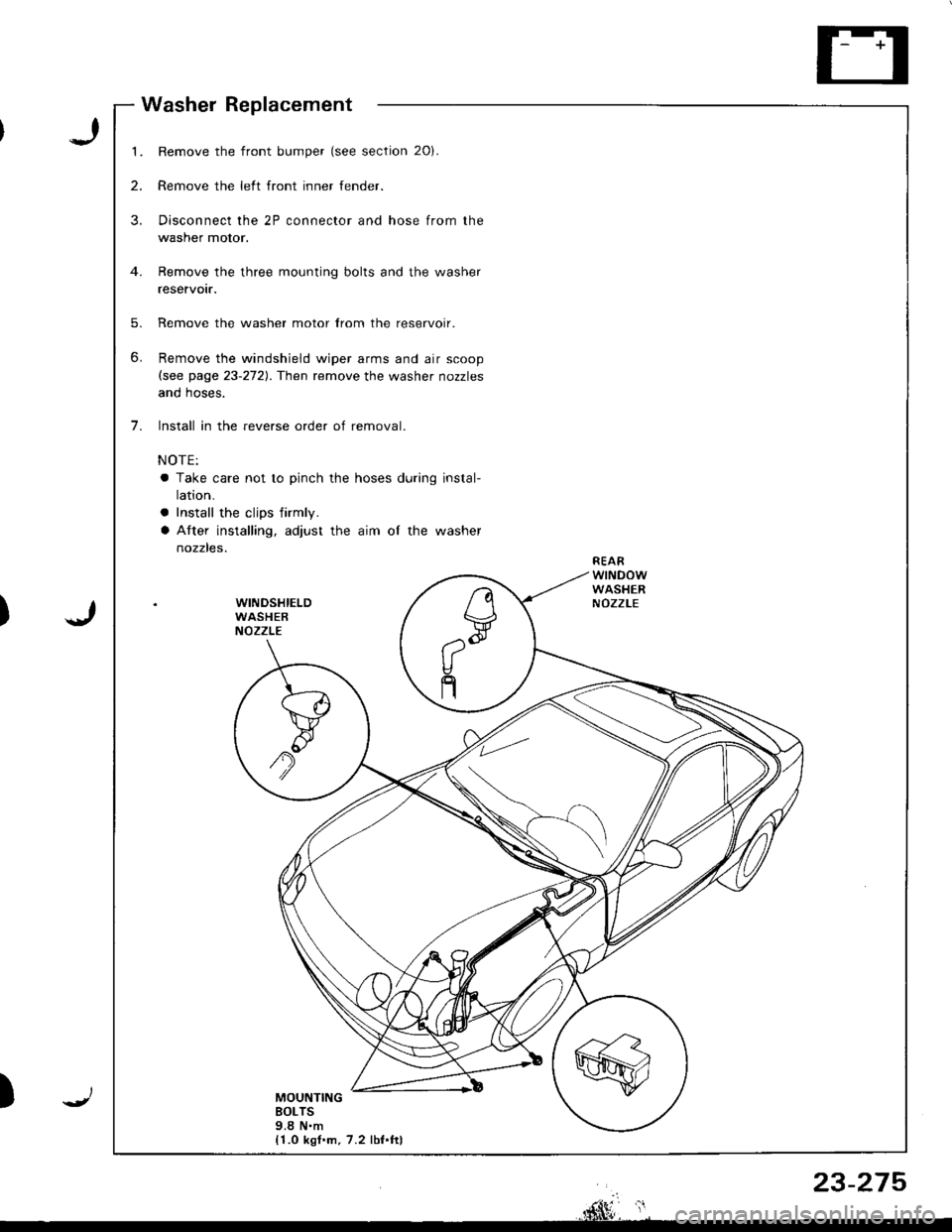
1.
2.
3.
5.
6.
7.
Remove the front bumper (see section 20).
Remove the left front inner fender.
Disconnect the 2P connector and hose from the
washer motor.
Remove the three mounting bolts and the washer
reservotr.
Remove the washer motor lrom the reservoir.
Remove the windshield wiper arms and air scoop(see page 23-272). Then remove the washer nozzles
anq noses.
Install in the reverse order of removal.
NOTE:
a Take care not to pinch the hoses during instal-
ralron.
a Install the cljps firmly.
a After installing, adjust the aim of the washer
nozzles.REAFWINDOWWASHERNOZZLEWINDSHIELDWASHERNOZZLE
MOUNTINGBOLTS9.8 N.m{1.0 kgl.m, 7.2 lbf.ftl
n
V,--"Q
V
n
Washer Replacement
J
J)
)
rnhlF*, ',
23-275