check engine HONDA INTEGRA 1998 4.G Workshop Manual
[x] Cancel search | Manufacturer: HONDA, Model Year: 1998, Model line: INTEGRA, Model: HONDA INTEGRA 1998 4.GPages: 1681, PDF Size: 54.22 MB
Page 1429 of 1681
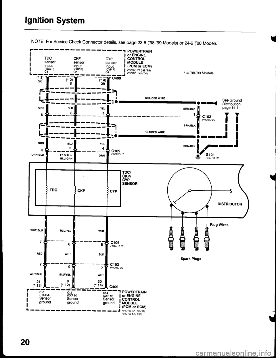
lgnition System
INorE: For service check connector details, see page 23-6 ('98-99 Models) or 2zl-6 ('00 Model).
POWERTRAINI a oielcirs '-"
rDc cKp cyp i coNTRoLsensor sensor sensor ! MODULEinout inout intu,t | /PCM.ri! input input inDut | (pCM or ECM)I g"oc et !cj
u"n,"." ! ----t
:jl--Jt---r-4,*"
"""*-Lf;
'':[:-==1-I=-==g=,-
u-{:::::L:::::+=i--- ""^".:-I'
.rr. s::3-.-:
;f:===-l_=* -=-f,*,,'fT
L-f--====E=--==i.l ""'"'"*'"'
=="=-'!---.!
I
-A 2r .|--___-OFNi 8LU II LT 8LU orI BLU/GRN
----o A c';;? F;o''","i:- F,to,l.,
Plug Wires
- - - -"-'lg- - - - - -^11 ct og
Spark Plugs
' Y-----rV-
- - - - ;V t#'",.
WHT.BLU ll BLU,"YEL I wHT
,. ?1, L--rrl:-,!-__,. ?Ll.oo,
cr3 c12 - - -.,,--a POWERTRATN(Dc Mr rckp M) icrb 6 | or ENGINEuensor Sensor Sensor i coNTRoLground ground grouno !laODuLi
20
Page 1464 of 1681
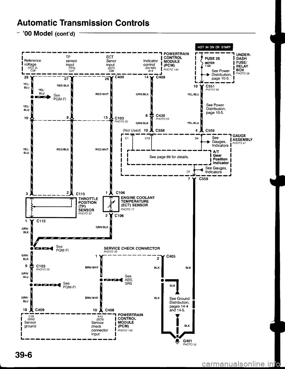
Automatic Transmission Controls
- '00 Model (cont'd)
[---;""'.f
-lc+os 141' c4o8 LJ-:*:IJ
|
:t
, ;:".1
*"",",1 "**-
I
-.11,[t*r'""
I .l ,.,1,","" .J,o*". i
r*ru;l
i.";-
- - -
Is"*
- - - - -
Fsil
- - -
;; I i.l{T'Fil^'- i I ;;
- -
I Ui3"*I voltage Inout
L js!'- - - - - - d": - - - - - 3t - - - - - roql j Hili:
i i-Ti*.*,*,, i F"H*i,'ll-------zrI_------16'rc4os 14tr' c408 LJ_j*::J
:tt, I ".ou.*l I I
r rii ^ r "."-,. r ^""",. r ". ::[ 9#3-
**[
[ [ X"., !r*g+;l"f-----
t
't
l;:,.il*[;,;
""T1",,,""
! ! !i;T-"{_
___-}.[1dnw'"t*il *"*-l "'o*n'l i'I---L-
I I NLi::--::::-:=a-*$$ti
.l_______l ",,, ,l ",,.
'r "*'
I_ITI ENGINE COOLANT
iddirioil I Jr l,.g:tilu;SENSOR lJJal PHora 17
c106
GFN/BLK
SERVICE CHECK CONNECTORPHOIO 76
-"^,:,[
.:
"{
'T[_:'*' "..1
;*liil, lFffi*'" I
c405
BLI
BLK I
I'
See GroundDistribution,pages 14-4and 14-5.
V
I ..
G401
39-6
Page 1606 of 1681
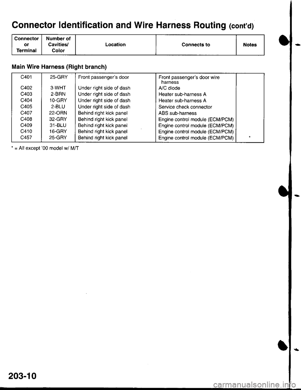
Connector ldentification and Wire Harness Routing (cont'd)
Connector
oI
Terminal
Number of
Cavities/
Color
LocationConnects toNotes
Main Wire Harness (Right branch)
c401
c402
c403
c404
c405
c407
c408
c409
c410
c457
25-GRY
3-WHT
2.BRN
1O-GRY
2-BLU
22-ORN
32-GRY
31-BLU
16-GRY
25-GRY
Front passengels door
Under right side of dash
Under right side of dash
Under right side of dash
Under right side of dash
Behind right kick panel
Behind right kick panel
Behind right kick panel
Behind right kick panel
Behind right kick panel
Fronl passenger's door wirenarness
A,/C diode
Heater sub-harness A
Heater sub-harness A
Service check connector
ABS sub-harness
Engine control module (ECM/PCM)
Engine control module (ECM/PCM)
Engine control module (ECM/PCM)
Engine control module (ECM/PCM)
. = All exceot '00 model w/ M/T
203-10
Page 1640 of 1681
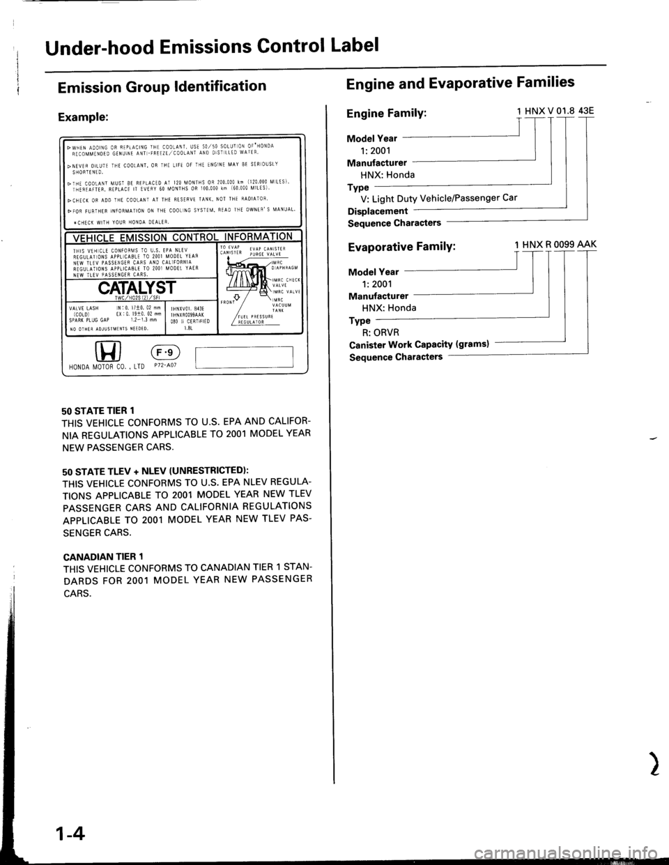
Under-hood Emissions Gontrol Label
Emission GrouP ldentification
Example:
50 STATE TIER 1
THIS VEHICLE CONFORMS TO U.S. EPA AND CALIFOR-
NIA REGULATIONS APPLICABLE TO 2OO1 MODEL YEAR
NEW PASSENGER CARS.
50 STATE TLEV + NLEV (UNRESTRICTEDI:
THIS VEHICLE CONFORMS TO U.S. EPA NLEV REGULA-
TIONS APPLICABLE TO 2OO1 MODEL YEAR NEW TLEV
PASSENGER CARS AND CALIFORNIA REGULATIONS
APPLICABLE TO 2OO1 MODEL YEAR NEW TLEV PAS.
SENGER CARS.
CANADIAN TIER 1
THIS VEHICLE CONFORMS TO CANADIAN TIER 1 STAN.
DARDS FOR 2OO1 MODEL YEAR NEW PASSENGER
HONDA l/0T0R c0. , LTD P72-401
>wHEN ADDTNG oR FEPtActNG THE co0LANT, usE 50,/50 soLUr oN oF'HoNDARECOMMTNDED GENUINE ANT -FREIZE,/COOtANT AND DIST LLED WATEF'
>NEVEfl DILUTE THE COOtANT, OR IHE LIFE OF THE ENGINF MAY BE SER]OUSLYSHORTENTO.
>THE COoLANT MUST BE BEPLACED AT I20 MONTHS OR 200.000 km (120 000 [,| LtS]'rnirilrren, B€pLAcE rT EvEFY 60 [roNTHs oR 100.000 km (60 000 [ilLEs)'
>CHEC( OR ADD THE COOLANI AT THE RESERVE TANK. NOT THE RADIATOF'
>FOR FI,JRTHER INFORMATION ON ]HE COOL]NG SYSTEM. READ THE OWNEN'S MANUAL'
ICHECK WITH YOUR HONOA DEALER,
ll,5lil, 5;i;,'iX;';'THIS VTH CtE CONFOF[IS TO U.S. EPA NLEVREGULATIONS APPL]CABLE TO 2OO] MODEL YTAsNEW TLTV PASSENGEF CAFS AIID CAL]FORNIAREGUTATIONS APPLICABLE TO 2OO] MOOET YAERNEW TLEV PASSENGER CARS.
IHNXVOI, 813FI HNXROO99AAKO8O II CERIIFIED1.81
VATVE LASH N:0. l/10. 02 mm(COLD) EX|0 19i0 02 mmSPARK PLUG GAP 1.2-1.3 mmIO OTHER ADJUSIMENIS NIEDTO,
Engine and EvaPorative Families
Engine Family:1HNXV01.8 43E
Model Year
1:2001
Manufacturer
HNX: Honda
Type
V: Light Duty Vehicle/Passenger Car
Displacement
Sequence Gharasters
Evaporative FamilY:1 HNX R OO99 AAK
Model Year
1:2001
Manufacturer
HNX: Honda
Type
R: ORVR
Ganister Work CaPacitY (gramsl
Sequence Characters
1-4
Page 1641 of 1681
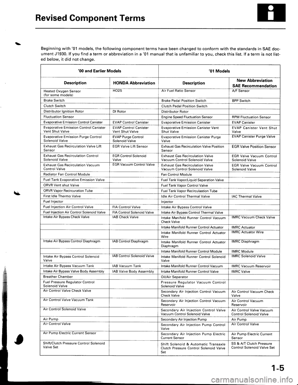
Revised Component Terms
\
\
Beginning with '01 models, the following component terms have been changed to conform with the standards in SAE doc-
ument J1930. lf you find a term or abbreviation in a '01 manual that is unfamiliar to you, check this list. lf a term is not list-
ed below, it did not chanqe.
'00 and Earlier Models'01 Models
DescriptionHONDA AbbreviationDescriptionNew Abbreviation
SAE Recommendation
Heated Oxygen Sensor(for some models)HO2SArr ruet llalto )ensorA,/F Sensor
Brake SwitchBrake Pedal Position SwitchBPP Switch
Clutch SwitchClutch Pedal Position Switch
Distributor lgnition RotorDl RotorDistributor Rotor
Fluctuation SensorEngine Speed Fluctuation SensorRPM Fluctuation Sensor
Evaporative Emission Control CanisterEVAP Control CanisterEvaDorative Emission CanisterEVAP Canister
Evaporative Emission Control CanisterVent Shut ValveEVAP Control CanisterVent Shut ValveEvaporative Emission Canister VentShut ValveEVAP Canister Vent ShutValve
Evaporative Emission Purge ControlSolenoid ValveEVAP Purge ControlSolenoid ValveEvaporative Emission Canister PurgeValveEVAP Uanister Purge Valve
Exhaust Gas Recirculation Valve LiftSensorEGR Valve Lift SensorExhaust Gas Recirculation Valve PositionSensorEGR Valve Position Sensor
Exhaust Gas Recirculation ControlSolenoid ValveEGR Control SolenoidValveExhaust Gas Recirculation ValveVacuum Control Solenoid ValveEGR Valve Vacuum ControlSolenoid Valve
Exhaust Gas Recirculation VacuumControl ValveEGR Vacuum Control ValveExhaust Gas Recirculation ValveVacuum Control Solenoid ValveEGR Valve Vacuum ControlSolenoid Valve
Radiator Fan Control ModuleFan Control Module
Fuel Tank Evaporative Emission ValveFuel Tank Vapor/Liquid Separation Valve
ORVR Vent shut ValveFuel Tank Vaoor Control Valve
ORVR Vaoor Recircuration TubeFuel Tank Vaoor Recirculastion Tube
First ldle Thermo Valveldle Air Control Thermal ValveIAC Thermal Valve
Fuel InjectorI njector
Fuel Iniection Air Control ValveFIA Control ValveIntake Air Bypass Control Valve
Fuel Injection Air Control Solenoid ValveFIA Control Solenoid ValveIntake Air Bypass Control Thermal Valvelntake Air BvDass Check ValveIAB Check ValveIntake Manifold Runner Control VacuumCheck ValveIMRC Vacuum Check Valve
Intake Manifold Runner Control ActuatorIMRC Actuator
Intake Manifold Runner Control ActuatorWireIMRC Actuator Wire
ntake Air Bypass Control DiaphragmIAB Control DiaphragmIntake Manifold Runner control ActuatorDiaphragmilvrr1u urapnragm
Intake Manifold Runner Control ModuleIMRC Module
Intake Air Bypass Control SolenoidValvelAts Control Solenoid ValveIntake Manifold Runner Control SolenoidValveIMRC Solenoid Valve
Intake Air Bvpass Vacuum TankIAB Vacuum TankIntake Manifold Runner Control VacuumIMRC Vacuum Reservoir
Intake Air Bypass Valve Body AssemblyIAB Valve Body AssemblVIntake Manifold Runner Control ValveIMRC Valve
Breather ChamberOil/Air Separator
Fuel Pressure Regulator ControlSolenoid ValvePressure Regulator Vacuum ControlSolenoid ValveAir Control Valve Check ValveSecondary Air In.jection Control VacuumCheck ValveAir Control Vacuum CheckValveArr Control Valve Vacuum TankSecondary Air Injection Control VacuumReservoirAir Control VacuumReservoirAir Control Solenoid ValveSecondary Air Injection Control ValveVacuum Control Solenoid ValveAir Control Valve VacuumControl Solenoid Valve
Air PumpSecondary Air Injection PumpAir PumpAir Control ValveSecondary Air Injection Pump ControlValveAir Control Valve
Arr rump tsreclnc uurrent bensorSecondary Air Injection Pump ElectricCurrent SensorAir Pump Electric CurrenlSensor
Shift/Clutch Pressure Control SolenoidValve SetShift Solenoid & Automatic TransaxleClutch Pressure Control Solenoid ValveSet
SS & A,/T Clutch PressureControl Solenoid Valve Set
1-5
Page 1654 of 1681
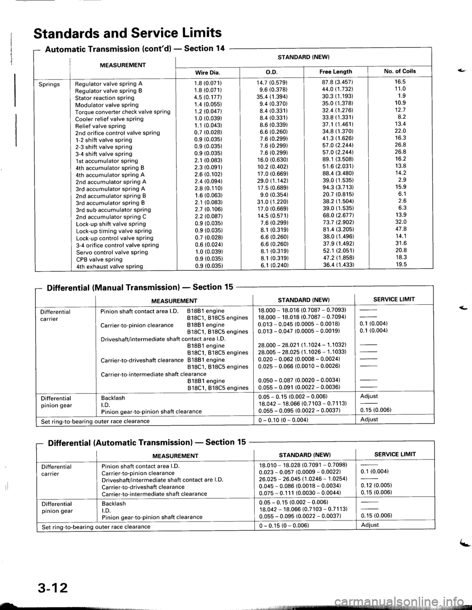
MFASIIREMENTSTANDARD (NEW}
Wire Dia.o.D.Free LengthNo. of Goils
SpringsRegulator valve spring ARegulator valve spring BStator reaction sPringModulator valve springTorque converter check valve springCooler relief valve springRelief valve spring2nd orifice control valve spring1-2 shift valve spring2-3 shift valve spring3-4 shift valve spring1st accumulator spring4th accumulator spring B4th accumulator spring A2nd accumulator spring A3rd accumulator spring A2nd accumulator spring B3rd accumulator spring B3rd sub accumulator spring2nd accumulator spring CLock-up shift valve springLock-up timing valve springLock-up control valve spring3-4 orifice control valve springServo control valve springCPB valve spring4th exhaust valve spring
1.8 (0.071)
1.8 (0.071)
4.5 rc.177].1.4 (0.05s)
1.2 10.047l.1.0 (0.039)
1.1 (0.043)
0.7 (0.0281
0.9 (0.035)
0.9 (0.035)
0.9 (0.035)
2.1 (0.083)
2.3 (0.091)
2.6 (0.102)
2.4 (0.094)
2.8 (0.110)
1.6 (0.063)
2.1 (0.083)
2.7 (0.106)
2.2 l0.o87l0.9 (0.035)
0.9 (0.035)
0.7 (0.028)
0.6 (0.024)
1.0 (0.039)
0.9 (0.0351
0.9 (0.035)
14.7 (0.5791
9.6 (0.378)
35.4 (1 .394)9.4 (0.370)
8.4 (0.331)
8.4 (0.331)
8.6 (0.339)
6.6 (0.260)
7.6 (0.299)
7.6 (0.299)
7.6 (0.299)
16.0 (0.630)
10.2 rc.402117.0 (0.669)
29.0 11.142117.5 (0.689)
9.0 (0.354)
31.0 (1 .220)17.0 (0.669)
14.5 (0.571)
7.6 (0.299)
8.1 (0.319)
6.6 (0.260)
6.6 (0.260)
8.1 (0.319)
8.1 (0.319)
6.1 (0.240)
87.8 (3.457)
44.0 (1.732\
30.3 (1.193)
35.0 (1.378)
32.4 (1.2761.
33.8 (1.331)
37.1 (1.461)
34.8 (1.370)
41.3 (1.626)
57.0 12.244157.0 12.244].89.1 (3.508)
s1.6 (2.0311
88.4 (3.480)
39.0 (1 .53s)94.3 (3.713)
20.7 (0.815)
38.2 (1.504)
39.0 (1.535)
68.0 (2.677)
73.7 (2.9021
81.4 (3.205)
38.0 (1.496)
37.9 (1.492)
52.1 (2.0511
47.2 (1 .858)36.4 (1.433)
16.51 1.01.910.912.78.213.422.01A ?
26.826.8't6.2
13.814.2z.J15.9o. l2.66.313.932.O47.814.1?1 A
20.8ttJ.JI v.5
Standards and Service Limits
Automatic Transmission (cont'd) - Section 14
Differential (Manual Transmission) - Section 15
Differential (Automatic Transmission) - Section 15
ilt5stlrrr, - 4,
MEASUREMENTSTANDARD (NEW}SERVICE LIMIT
Differentialca rnerPinion shaft contact area l.D. 81881 engineB18C1, 818C5 engines
Carrier-to-pinionclearance Bl88lengine818C1, 818C5 enginesDriveshafVintermediate shaft contact area l.D.81881 engine818C1. 818C5 engines
Carrier-to-driveshaft clearance 81881 engine818C1, 818C5 engines
Carrier-to-intermediate shaft clea rance81881 engine818C1, 818C5 engines
18.000 - 18.016 (0.7087 - 0.7093)18.000 - 18.018 (0.7087 - 0.7094)0.013 - 0.045 (0.0005 - 0.0018)0.013 - 0.047 (0.0005 - 0.0019)
28.000 - 28.021 11.1024 - 1.1032].28.005 - 28.025 l1 .'�t026 - 1 .1 033)
0.020 - 0.062 (0.0008 - 0.0024)0.025 - 0.066 (0.0010 - 0.00261
0.050 - 0.087 (0.0020 - 0.0034)0.055 - 0.091 (0.0022 - 0.0036)
- toooot0.1 (0.004)
Differentialpinion gearBacklasht.D.Pinion gear-to-pinion shaft clearance
0.05 - 0.15 (0.002 - 0.006)18.042 - 18.066 (0.7103 - 0.71 1 3)0.055 - 0.095 (0.0022 - 0.0037)
Adjust
0.15 (0.006)
Set ring-to-bearing)uter race clearance0 - 0.10 (0 - 0.004)Adjust
nsmlssaonl - Sectton
MEASUREMENTSERVICE LIMITSTANDARD (NEW}
Differentialca rrierPinion shaft contact area l.D.Carrier-to-pinion clearanceDriveshaft/i ntermediate shaft contact are l.D.
Carrier-to-driveshaft clearanceCarrier-to-intermediate shaft clearance
18.010 - 18.028 (0.7091 - 0.7098)0.023 - 0.057 (0.0009 - 0.0022)26.025 - 26.045 11.0246 - 1.02541
0.045 - 0.086 (0.0018 - 0.0034)0.075 - 0.1 11 (0.0030 - 0.0044)
0.1 (0.004)
0.12 (0.005)
0.15 (0.006)
Differentialpinion gearBacklasht.D.Pinion gear-to-pinion shaft clearance
0.05 - 0.15 (0.002 - 0.006)18.042 - 18.066 (0.7 103 - 0.71 1 3)0.055 - 0.095 (0.0022 - 0.0037)0.15 (0.006)
Set ring-to-bearing outer race clearance0 - 0.15 (0 - 0.006)Adiust
uL-
3-12
(-
Page 1672 of 1681
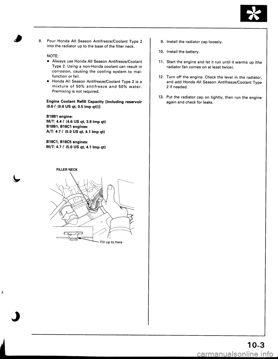
tt.Pour Honda All Season Antifreeze/Coolant Type 2into the radiator up to the base of the filler neck.
NOTE:
o Always use Honda All Season Antifreeze/Coolant
Type 2. Using a non-Honda coolant can result incorrosion, causing the cooling system to mal-function or fail.
o Honda All Season Antifreeze/Coolant Type 2 is amixture of 50% antifreeze and 50% water.Premixing is not required.
Engine Coolant Refill Gapacity [including reservoir(0.6 f {0.6 US qt, 0.5 lmp qtlll:
81881 engine:
M/T: 4.4 / {4.6 US qt, 3.9 lmp qtl
B18B1, Bl8Cl engines:
AIT:4.7 / (5.0 US qt,4.1 lmp qtl
818C1, B18C5 engines:
MIT:4.7 / (5.0 US qt,4.1 lmp qtl
FILLER NECK
Fill up to here
9.
10.
11.
12.
Install the radiator cap loosely.
Install the battery.
Start the engine and let it run until it warms up (the
radiator fan comes on at least twice).
Turn off the engine. Check the level in the radiator,
and add Honda All Season Antifreeze/Coolant Type2 if needed.
Put the radiator cap on tightly, then run the engine
again and check for leaks.
13.