check engine HONDA INTEGRA 1998 4.G Workshop Manual
[x] Cancel search | Manufacturer: HONDA, Model Year: 1998, Model line: INTEGRA, Model: HONDA INTEGRA 1998 4.GPages: 1681, PDF Size: 54.22 MB
Page 779 of 1681
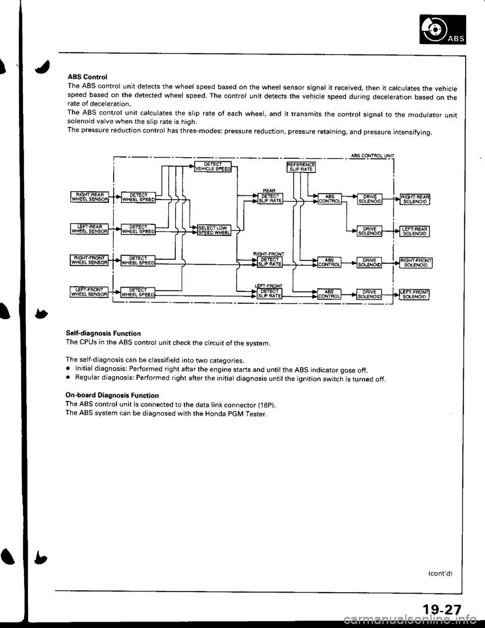
IABS Control
The ABS control unit detects the wheel speed based on the wheel sensor signal it received, then it calculates the vehiclespeed based on the detected wheel speed. The control unit detects the vehicle speed during deceleration based on therate of deceleration.
The ABS control unit calculates the slip rate of each wheel, and it transmits the control signal to the modulator unitsolenoid valve when the slip rate is high.
The pressure reduction control has three-modes: pressure reduction, pressure retaining, and pressure intensifying.
Self-diagnosis Function
The CPUS in the ABS control unit check the circuit of the system.
The self-diagnosis can be classifield into two categories.. Initial diagnosis: Performed right after the engine starts and until the ABS indicator gose off.. Regular diagnosis: Performed right after the initial diagnosis until the ignition switch isturnedoff.
On-board Diagnosis Function
The ABS control unit is connected to the data link connector fi6p).The ABS system can be diagnosed with the Honda PGM Tester.
(cont'd)
19-27
Page 789 of 1681
I
\
I
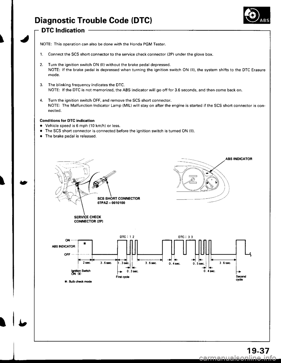
Diagnostic Trouble Code (DTC)
DTG lndication
a
t
NOTE: This operation can also be done with the Honda PGM Tester.
1. Connect the SCS short connector to the service check connector (2P) under the glove box,
2. Turn the ignition switch ON (ll) without the brake pedal depressed.
NOTE: lf the brake pedal is depressed when turning the ignition switch ON (ll), the system shifts to the DTC Erasure
mode.
3. The blinking frequency indicates the DTC.
NOTE: lf the DTC is not memorized, the ABS indicator will go off fo r 3.6 seconds, and then come back on.
4. Turn the ignition switch OFF, and remove the SCS short connector.
NOTE: The Malfunction Indicator Lamp (MlL) will stay on after the engine is started if the SCS shon connector is con-
nected.
Conditions lor DTC indication
. Vehicle speed is 6 mph (10 km/h) or less.
. The SCS short connector is connected before the ignition switch is turned ON {ll).
. The brake pedal is released.
ABS INOICATOB
SCS SHORT CONNECTORo?PAZ - 0010100
SERVICE CHECKCONNECTOR I2PI
DTC : 3 3
b
Page 794 of 1681
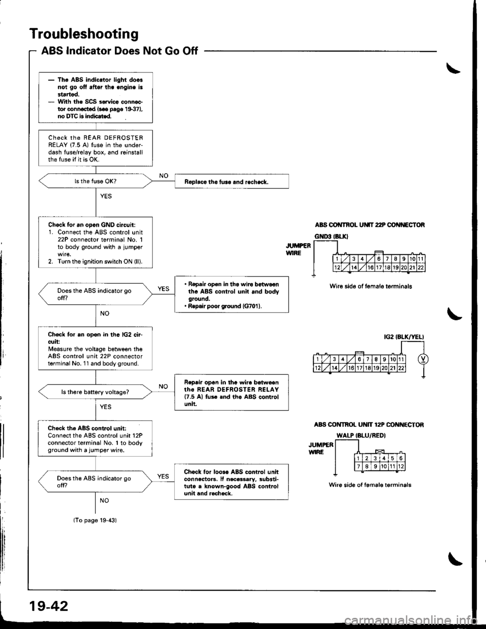
Troubleshooting
ABS Indicator Does Not Go Off
JUMPERWIRE
ABS OO TNOL UMT 22P OO'{NECTOR
Wire side of temalo terminalg
A8S COI{TROL Ut{lT 12P OO I{ECTOR
JUMPEFWIRE
Wire side of femal€ terminala
|G2 IALK/YELI
- The ABS indicltor light doosnot go ofl aftor lhe engine is3tartod.- With the SCS sorvico connoctor connoct d l.oe page 19371,no DTC b indbat€d.
ChECK thE REAF DEFROSTERRELAY (7.5 A) fuse in the under-dash fuse/relay box, and reinstallthe fuso if it is OK.
Roplaco tho tusa and rocheck.
Chock for an opcn GND circuit:1. Connect the ABS control unit22P connector terminal No. 1to body ground with a jumper
2. Turn the ignition switch ON (ll).
. Ropair opon in tha wiro botwocntho ABS control unit and bodyground.' Ropair poo. ground {G701 }.
Check for an open in thc lG2 ci.-cuit:Measure the voltage botween theABS control unit 22P connectorterminal No. 11 and body ground.
Roprir opon in thc wira bdtwoentho REAR OEFROSTER RELAY17.5 Al fu$ end th. ABS controlunit.
ls th6re battery voltage?
Check the ABS contJol unit:Connect the ABS control unit 12Pconnector terminal No. 1 to bodyground with a jumper wire.
Chock for looao ABS control unhconncctoas, It nacas3aly, sub3ti-tuto a known-good ABS controlunit and r.check.
(To page 19-43)
19-42
Page 796 of 1681
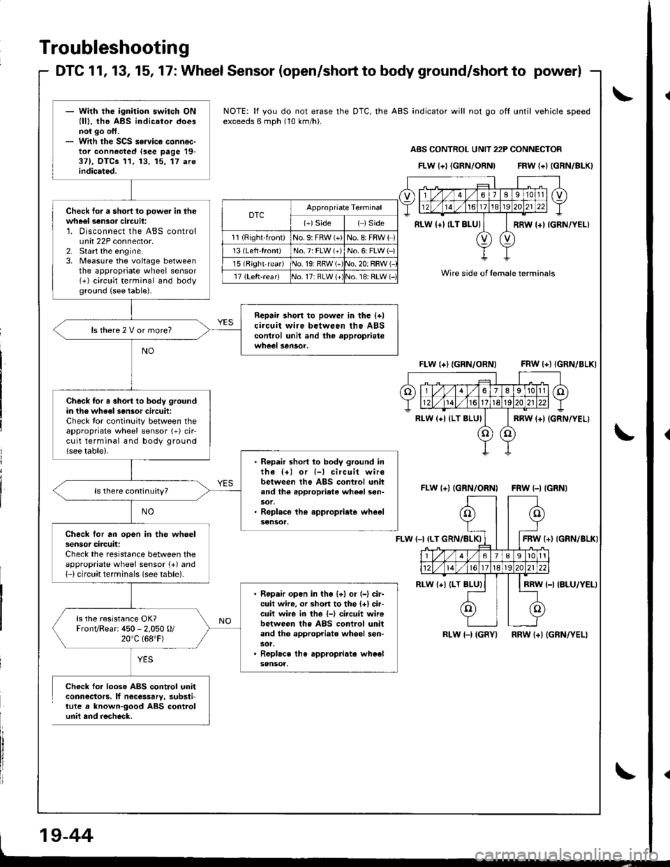
- With the ignition switch ON(lll, the ABS indicator doesnot go off.- With the SCS s€.vice connec-tor connected lsee page 19-37), OTCS 11, 13, 15, 17 areindicated.
Check for a short to pow6r in thewheel sensor circuii:1. Disconnect the ABS controlu nit 22P connector.2. Start the engine.3, Measure the voltage betweenthe appropriate wheel sensor(+) circlit terminal and bodyground (see table).
Repair short to power in the {+)circuit wire between the ABScontrol unil and the approprialewheel sensor.
ls there 2 V or more?
Check for a short to body groundin th6 wheel sensor circuil:Check tor continuity between theappropriate wheel sensor (+) cir-cuit terminal and body ground(see table).. Ropair short lo body ground inthe {+) or {-l circuit wirebetween tho ABS contlol unitand th6 .ppropriate whe€l sen-
. Roplaco the .ppropliate wheelsensot.
ls there continuity?
Check for an open in the wheelsensor circuit:Check the resistance between theappropriate wheel sensor (+) and1-) circuit terminals (see table).
Ropair open in the {+) or (-} cir-cuit wire, or 3hort to the l+) cir-cuit wire in the l-l circuit wirebetween tho ABS control unitand th6 appropriate whgel 3en-
Replace th6 appropdate wh€elsensot.
ls the resistance OK?FronvRear: 450 - 2,050 O/20"c (68.F)
NOTE: lf you do not erase the DTC, the ABS indicator will not go off until vehicle speedexceeds 6 mph (10 km/h).
ABS CONTNOL UNIT 22P CONNECTOF
FLw {+l {GRN/ORN) FRw {+} (GRN/BLKI
oTcAppropriate Terminal
(+)Side( )side
11 (Right-front)No. 9: FRW (+)No. 8: FBW {-)
13 (Left'front)No.7: FLW (+)No.6: FLW 1-)
l5lBight-rear) iNo. 19:RRW (+!o. 20: RBW (-
17 (Left'r€af)17: RLW {+',1o. 18: RLW (-Wire side of lemale terminals
FLW (+) (GRN/ORN) FRW l+){GRN/BLK)
FLw l+l (GRN/ORNI FRW {-) {GRN}
FLW t-l(+l (GRN/BLKI
RL(-I {BLU/YELI
RLW l-) (GBY) RRW (+) (GRN/YEL)
Check for loose ABS control unitconnectors. lf necessary. substi-tute a known-good ABS controlunii and recheck.
RLW {+l (LT BLUI
RLw (+l {LT BLU}
-t(o
___r
l'!*
6l89l01t
1417t8t920
| ***-t
(()
Y
Troubleshooting
DTC 1 1, 13, 15, 17 : Wheel Sensor (open/short to body ground/short to power)
\
L
9-44
\
Page 806 of 1681
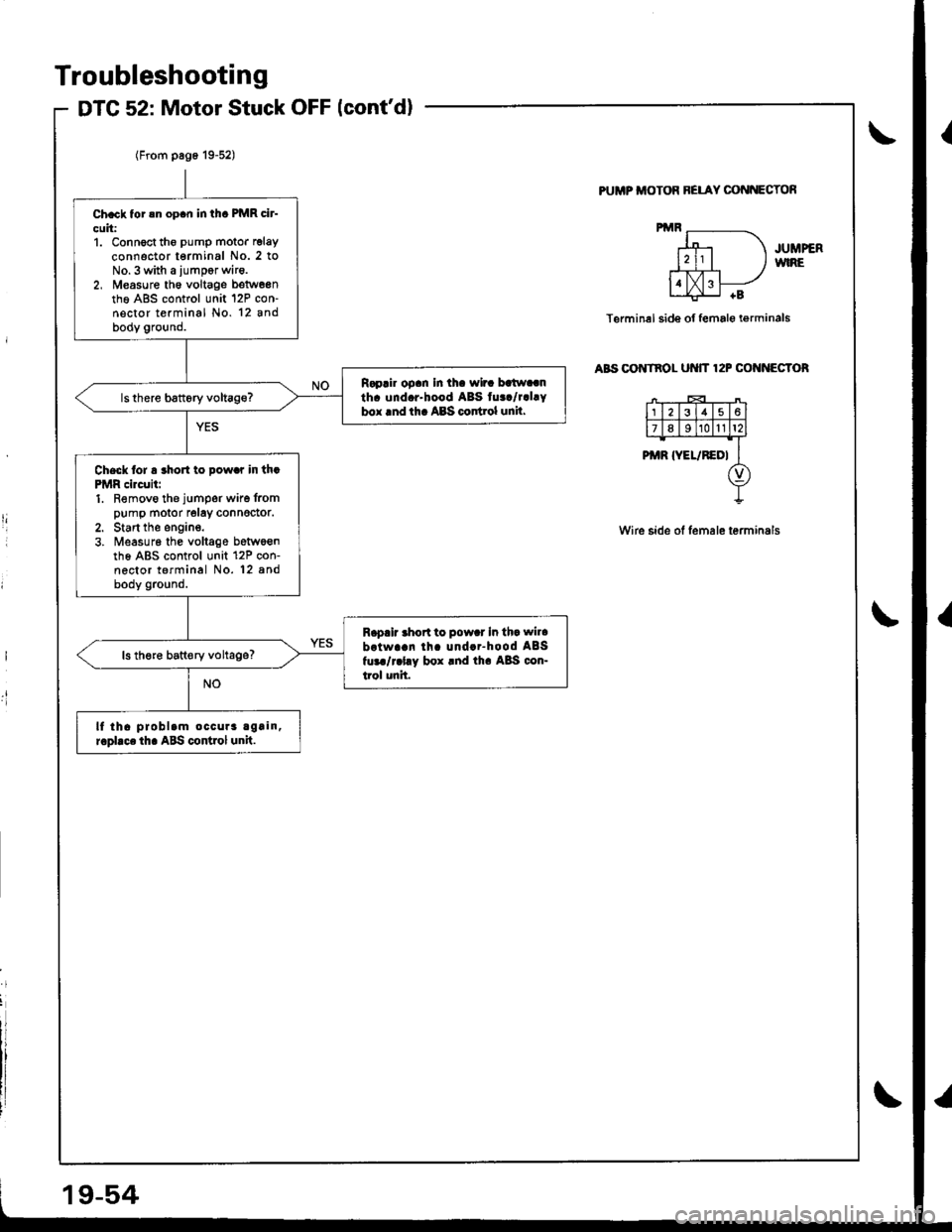
Troubleshooting
DTG 52: Motor Stuck OFF lcont'd)
PUMP ITIOTOR BELAY CONNECTOf,
JUMPERWIRE
Terminel side of female i€rminals
aBs oo tnol ut{tT 12P cof{f{EGToR
Wire side of lemale terminals
I
.t!
Ch.ck tor !n op.n in thc PMR cir-
cuit:1. Connoct tho pump motor relay
connector terminal No. 2 toNo.3 with a iumpor wir6.2, M€asure th6 voltage betw6entho A8S control unit 12P con-nector terminal No. 12 andbody ground.
R.p.ir op.n In th. wir. batw..nth. und.r-hood ABS tu../r.l.Ybox lnd th. ABS codrol unil.
Check lor a rho to pow.r in th.PMR circuii:1. Removo the jumper wire frompump motor relay connedor.2. Start the engine.3. ireasur6 the voltage betwoenth6 ABS control unit 12P con-nector terminal No. 12 8ndbody ground.
R.p.ir .hort to pow.r In th. wil.
brtwa!n lh. und..-hood ABSfur./r.l.y box rnd th. A8S con-trol unit.
ls th€re batt€ry voltage?
lf tha problam occura again,r.pllce th. ABS control unit.
Page 813 of 1681
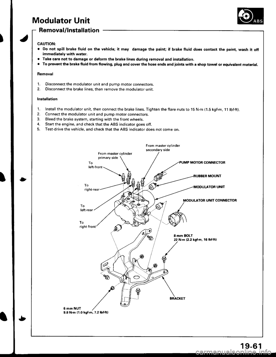
Modulator Unit
Removal/lnstallation
CAUTION:
. Do not spill brake fluid on lhe vehicle; it may damage the paint; il brake fluid does contact the paint, wash it offimmediately with water.
. Tak€ care notto damage or delorm the brake lines during removal and installation.. To provont the brake fluid ftom flowing, plug and cover the hos€ ends and ioints with a shop towel or equiyalent material.
Removal
1. Disconnect the modulator unit and DUmD motor connectors.
2. Disconnect the brake lines, then remove the modulator unit.
Installation
1. lnstall the modulator unit, then connect the brake lines. Tighten the flare nuts to 15 N.m (1.5 kgf.m, 11 lbf.ft).2. Connect the modulator unit and pump motor connectors.
3. Bleed the brake system, starting with the front wheels.
4. Start the engine, and check that the ABS indicator goes off.
5. Test-drive the vehicle, and check that the ABS indicator does not come on.
From master cylinder
from master cylinderprimary side
PUMP MOTOB CONNECTOR
MOUNT
UNlT
MODULATOR UNIT CONNECTOR
toright front
8 mm EOLT22 N.m {2.2 kg[.m, 16 lbl.ftl
6 mm NUT9.8 N.m 11.0 ks{.m,7.2lbtftl
9-6
Page 814 of 1681
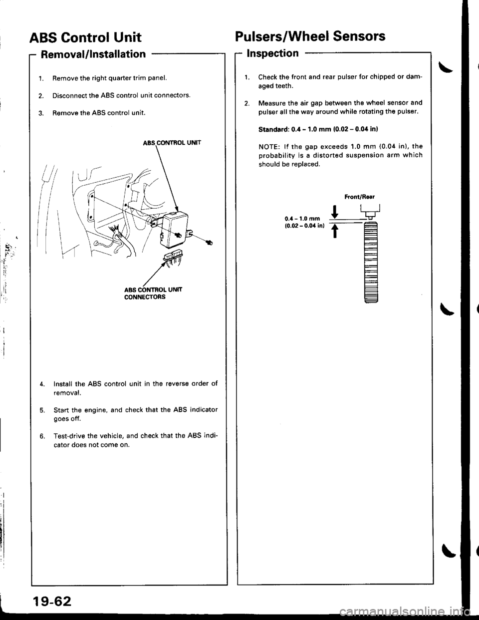
ABS Control Unit
RemovaUlnstallation
1. Remove the right quarter trim panel.
2. Disconnect the ABS control unit connectors.
3. Remove the ABS control unit.
Pulsers/Wheel Sensors
Inspection
/t
l\
I
Check the front and rear pulser for chipped or dam-
aged teeth.
Measure the air gap between tho wheel sensor and
pulser sllthe way around while rotating the pulser.
Standard: 0.4 - 1.0 mm (0.02 - 0.04 in)
NOTE: lf the gap exceeds 1.0 mm (0.04 in), the
probability is a distorted suspension arm which
should be reDlaced.
Front/R..1
L-TJ
.t-
t=
l-
Et-E_
Install the ABS control unit in the reverse order of
removal.
Start the engine, and check that the ABS indicator
goes off.
Test-drive the vehicle, and check that the ABS indi-
cator does not come on.
19-62
Page 995 of 1681
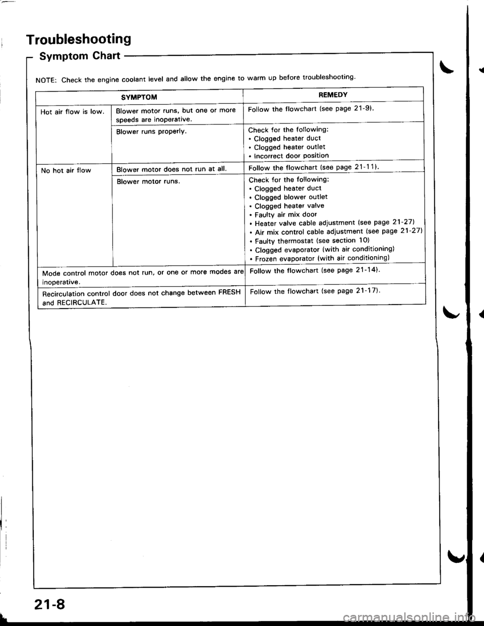
SYMPTOMREMEDY
Hot air tlow is low.Blower motor runs, but one or more
speeds are inoperative.
Follow the flowchart (see page 21-9).
Blower runs propetly.Check for the following:. Clogged heater duct
. Clogged heater outlet
. Incorrect door Position
No hot air tlowBlower motor does not run at all.Follow the flowchart {see page 21-11}
Blower motor runs.Check for the following:
. clogged heater duct
. Clogged blower outlet. Clogged heatet valve
. Faultv air mix door
. Heater valve cable adjustment lsee page 21-27].
. Air mix control cable adiustment {see page 21-27)
. Faulty thermostat (see section 10)
. Clogged evsporator (with air conditioning)
. Frozen evaDorator (with air conditioning)
Mode control motor does not run, or one or more mooes are
inoDeratave.
Follow the flowchart (see page 21-14).
Recirculation control door does not change between FRESH
and RECIRCULATE.
Follow the flowchart {see page 21-17).
Troubleshooting
Symptom Chart
NOTE: Check the engin€ coolant level and allow the engine to warm up before troubleshooting'
21-8
v
Page 1025 of 1681
J
Troubleshooting
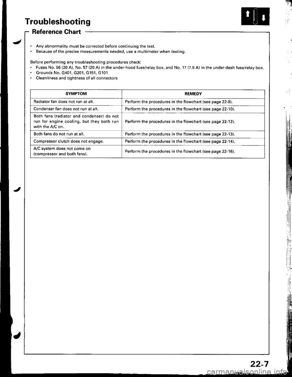
Reference Chart
. Any abnormality must be corrected before continuing the test.. Because of the precise measurements needed, use a multimeter when testing.
Before performing any troubleshooting procedures check:. Fuses No, 56 (20 A), No. 57 (20 A) in the under-hood fuse/relay box, and No. 17 {7.5 A) in rhe under-dash fuse/relay box.. Grounds No. G401, G201, G151, G101. Cleanliness and tightness of all connectors
I'IT
I
I
SYMPTOMREMEDY
Radiator fan does not run at all.Perform the procedures in the flowchart {see page 22-8).
Condenser fan does not run at all,Perform the procedures in the flowchart (see page 22-1O1.
Both fans {radiator and condenser) do not
run for engine cooling, but they both run
with the IVC on.
Perform the procedures in the tlowchart (see page 22-12).
Both fans do not run at all.Perform the procedures in the flowchart (see page 22-13).
Compressor clutch does not engage.Perform the procedures in the flowchart (see page 22-14).
l'lc system does not come on
{compressor and both fans).Perform the procedures in the flowchart (see page 22-15).
22-7
Page 1030 of 1681
Troubleshooting
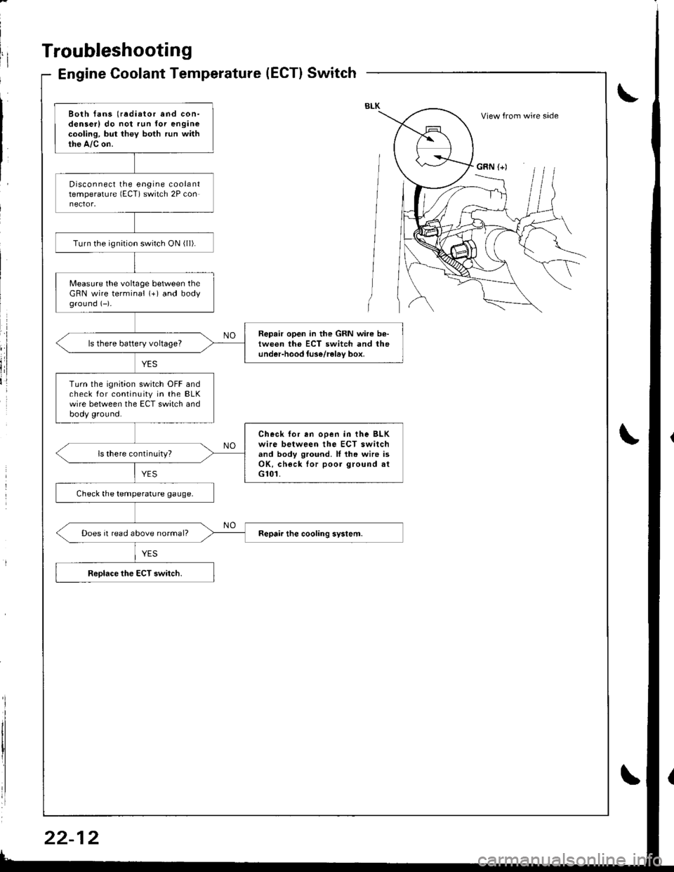
Engine Coolant Temperature(ECT}Switch
Both fans (radiator and con-denserl do not run for enginecooling, but they both run withthe A,/c on.
Disconnect the engine coolanttemperature lECT) switch 2P con
Turn the ignirion switch ON ( ll).
Measure the voltage between theGRN wire terminal (+) and bodyground (-)-
Repair open in the GRN wire b€-tween the ECT switch and theunder-hood luse/rel6v box,ls there battery voltageT
Turn the ignition switch OFF andcheck for continuity in the BLKwire between the ECT switch andbody ground.
Check for en ooen in the BLKwire between the ECT switchand body ground. ll th. wire isOK, check lor poor ground atG101.
ls there continuity?
Check the temperature gauge.
Does it read above normal?
View from wire side
GRN (+)