battery HONDA INTEGRA 1998 4.G Workshop Manual
[x] Cancel search | Manufacturer: HONDA, Model Year: 1998, Model line: INTEGRA, Model: HONDA INTEGRA 1998 4.GPages: 1681, PDF Size: 54.22 MB
Page 1479 of 1681
A/C Gompressor Controls (conrd)
- How the Circuit Works
Battery voltage is supplied through fuse 56 to the
A,/C compressor clutch relay contacts at all times.
With the ignition switch in ON (ll), voltage is applied
to the coil of the A,/C compressor clutch relay
through fuse 17. When you push the A,/C switch
ON, and the heater fan switch is in posation 1, 2, 3,
or 4, a "ground" input is provided to the engine or
powertrain control module (ECM or PCM) through
the A,/C thermostat and the A,/C pressure switch.
The A,/C compressor clutch relay is grounded by the
engine or powertrain control module (ECM or PCM).
When energized, the A,/C compressor clutch relay
allows battery voltage to turn on the A,/C
comDressor clutch,
The A,/C ON indicator light comes on when the A"/C
system is requested.
A,/C Thermostat
The A,/C thermostat is located on the evaoorator
housing. The AJC thermostat turns off the A,/C
compressor clutch if the temperature at the
evaporator goes below 3'C (37'F). This prevents
condensation from freezing on the evaporator fins
and blocking the air delivery into the passenger
compartment. The blower motor will keep running
when the sensor lurns off the compressor.
A,/C Pressure Switch
The A,/C pressure switch is located in the condenser
outlet line where refrigerant is in a high
temperature/high pressure liquid state. The switch
will sense abnormally high or low pressure, and
open the circuit. This removes ground, and the
compressor will stop running.
Refer to the Service Manual (Section 22,
Air Conditioning) for specific tests or
troubleshooting procedures.
62-2
Page 1500 of 1681
Gauges (cont'd)
- How the Circuit Works
When the ignition switch is in ON (ll) or START (lll),
battery voltage is supplied through fuse 25 to the
gauges in the gauge assembly.
Speedometer and Odometer
The odometer and speedometer drive circuits
receive pulses lrom the vehicle speed sensor
(VSS). The pulse rate increases as the car
accelerates. The frequency and duration of these
input pulses are measured and displayed by the
speedometer, odometer and tripmeter.
Tachometer ('98-'99 Models)
The tachometer drive circuit receives oulses from
the ignition control module (lCM) in the distributor
assembly. The solid-state tachometer then displays
these pulses as engine speed. For each 200 pulses
per minute from the ignition control module (lCM),
the tachometer displays 100 RPM.
Tachometer ('00 Model)
The tachometer drive circuit receives pulses f rom
the PCM or ECM. The solid-state tachometer then
displays these pulses as engine speed. For each
200 oulses oer minute trom the PCM or ECM the
tachometer displays 1 00 RPM.
Engine Coolant Temperature Gauge and Fuel
Gauge
The engine coolant temperature gauge has two
intersecting coils wound around a permanent
magnet rotor. Voltage applied to the coils, through
fuse 25, generates a magnetic field. The magnetic
field, controlled by the engine coolant temperature
gauge sending unit, causes the rotor to rotate and
the gauge needle to move. As the resistance in the
sending unit varies, current through the gauge coils
changes. The gauge needle moves toward the coil
with the strongest magnetic tield. The fuel gauge
works the same way.
The engine coolant temperature gauge sending
unit's resistance varies from about 137 ohms at low
engine temperature to between 30-46 ohms at high
temperature (radiator fan running).
The fuel gauge sending unit's resistance varies from
about 2-5 ohms at full, to about 110 ohms at empty.
When you turn the ignition switch to LOCK (0), the
gauge remains at the last reading until you turn lhe
ignition switch to ON (ll) or START (lll) again.
Refer to the Service Manual (Section 23, Electrical)
for specific tests or troubleshooting procedures.
81'2
Page 1507 of 1681
Wiperffasher (contd)
- How the Circuit Works
When the ignition switch is in ON (ll) or START (lll),
battery voltage is applied to lhe windshield
wiper/washer switch, and the windshield wiper
motor.
Low Speed
When you turn the wiper switch to LO, the wiper
motor's low speed winding is grounded through the
BLU wire and the LO speed contacts of the wiper
switch at G401, and the wipers run at low speed.
ParUOfi
When you turn the wiper switch OFF, the integrated
control unit (PARK input) grounds the wiper motor
through the BLUMHT wire. The cam switch on the
motor signals the integrated control unit that the
wipers are in the PARK position; the control unit
then removes ground from the motor, and the
wipers stop in the PARK position.
High Speed
When the wiper switch is in Hl, the high speed
windings ol the windshield wiper motor are
grounded through the BLUI/EL wire and the Hl
contacts of the wiper switch at G401 , and the
wipers run at high speed.
Intermittent
When the wiper switch is in lNT, battery voltage is
applied through the YEUBLU wire to the integrated
control unit (lntermittent wiper ON input). The
integrated control unit (lntermittenvPark Wiper
Control) grounds the low speed windings of the
wiper motor and the wipers make a single sweep
every few seconds (See Low Speed above). When
the wiper returns to the PARK position, the park
switch applies battery voltage through the
BLUMHT wire to the integrated control unit (PARK
input), and the wipers stop in the PARK position.
91-2
Mist
When you pull the wiper switch down to MIST
position, the high speed windings of the wiper motor
are grounded through the BLU//EL wire and the
closed contacts of the mist switch at G401, and the
wipers make one pass across the windshield at high
speed. The PABKOFF tunction then takes over and
the wrpers stop in the PARK position.
Washer
When you pull the wiper switch toward you to turn on
the washer switch, battery voltage is applied to the
washer motor. The motor pumps fluid onto the
windshield until you release the lever. On models
with combined wiper/washer operation (Canada), the
integrated control unit (windshield washer ON input)
senses power al the BLI(GRN wire terminal and
runs the washer motor whenever the wioers run.
Reter to the Service irlanual (Section 23, Electrical)
for specific tests or troubleshooting procedures.
Page 1522 of 1681
![HONDA INTEGRA 1998 4.G Workshop Manual - Canada Only
UNDER-OASHFUSE/RELAYBOX
T@-];----
_ti:___:_c440
;
J
j
r-----
I See Power: Distribution,I page 10-8.
I
IL-----
FUSE 20{FUNNING LIGHTS)
See BrakeSystemIndicalor Light
c439
c41sc416
c416
ar HONDA INTEGRA 1998 4.G Workshop Manual - Canada Only
UNDER-OASHFUSE/RELAYBOX
T@-];----
_ti:___:_c440
;
J
j
r-----
I See Power: Distribution,I page 10-8.
I
IL-----
FUSE 20{FUNNING LIGHTS)
See BrakeSystemIndicalor Light
c439
c41sc416
c416
ar](/img/13/6069/w960_6069-1521.png)
- Canada Only
UNDER-OASHFUSE/RELAYBOX
T@-];----
_ti:___:_c440
;
J
j
r-----
I See Power: Distribution,I page 10-8.
I
IL-----
FUSE 20{FUNNING LIGHTS)
See BrakeSystemIndicalor Light
c439
c41sc416
c416
arr<
DAYTIMERUNNINGLIGHTSCONTROLUNIT
c302
1
WHT/NEO
WHT/FEO
DAYTIMERUNNINGLIGHTSRESISTOR
c307c440
.I UNDER.DASHI FUSE/RELAYI 8OXI Pqofa 53
c504
18
r
I
I
1
A C508
l-l-l PARKINGI ' I BRAKE| .( | swrrcH| ..- t I Closed with4 parking brake- applreo.PHAfO 71
c301
See GroundDistribution,page 14-4.
Y
I
I
a:."-
Lights-on Batteryinpul
Headlight control
lgnitionBrake system indicatorlight control
GroundParking brake input
r-910-1-
1 10-9
Page 1523 of 1681
Headlights (cont'd)
- How the Circuit Works
Low Beam OperationRefer to the Service Manual (Section 23, Electrical)
for specific tests or troubleshooting procedures.
With the headlight switch in HEAD and the dimmer
switch in LO, current flows through the headlight
switch, fuse 21 , tuse 22, and the low beam
filaments to ground, and the low beams come on.
tligh Beam Operation
With the headlight switch in HEAD and the dimmer
switch in Hl, current flows through the headlight
switch, dimmer/passing switch, fuses 4, 5, 21, and
22, and the low and high beam filaments to ground,
and the low and high beams come on.
Current also tlows through the high beam indicator
light to ground. The high beam indicator comes on
to remind the driver that the high beams are on.
Flash operation
The flash feature works with the headlight switch in
OFF, PARK, or HEAD (low beams). When you
move the flash-to-pass switch to ON, current flows
through the switch, fuses 4 and 5, and the high
beam filaments to ground, and the high beams
flash. The high beam indicator also flashes during
the flash oDeration. The flash function has no effect
it the high beams are already on.
Daytime Running Lights Day Operation
When you turn the ignition to ON (ll) with the
parking brake released, the daytime running lights
control unit supplies battery voltage at the
WHT/RED wire. This voltage is applied to the high
beam headlights through the daytime running lights
resistor. Each high beam headlight receives less
than battery voltage causing them to come on al
reduced brightness.
lf the parking brake is set, a ground signal is applied
to the daytime running lights control unit at the
RED/GRN wire. It the parking brake is set when you
first turn the ignition switch to ON (ll), the high beam
headlights will remain off until you release the
parking brake. Once the high beam headlights are
in day mode, setting the parking brake will not
cause the headlights to turn off . When low or high
beam operation is requested, baftery voltage trom
the headlight switch is applied to the daytime
running light control unit via the RED/vVHT wire.
The daytime running light control unit then
discontinues the daytime running light mode.
1 10-10
Page 1540 of 1681
Power Windows (conrd)
- How the Circuit Works
CAUTION: You could iniure your arms, hands,
or fingers if you unintentionally switch the
driver's window to "automatic down,' while
working in that door with the power on. Discon-
nect the window switch connector or the battery
when working in the driver's door.
System Description
The operation of the power windows is controlled by
the main switch in the power window masler switch.
When the main switch is in OFF, only the driver's
door window can be opened or closed. With the main
switch ON, all windows can be opened or closed
either by switches in the master panel, or switches in
the doors. The driver's window switch also has an
automatic down mode which is tumed on by pushing
the switch down to its second position.
The power windows are driven by reversible motors.
Each motor is protected by a built-in circuit breaker.
lf the window switch is held on too long (with the
window obstructed, or after the window is fully up or
down), the circuit breaker opens the circuit. The
circuit breaker resels automaticallV as it cools.
Driver's Window
With the ignition switch in ON (tt), vottage isprovided to the coil ol the power window relay
through fuse 24. The contacts of the power window
relay close, and voltage is applied to the driver's
switch. When you push the power window master
switch to Uq voltage is applied to the driver's power
window motor. (The motor's ground path is backthrough the power window master switch.) The
driver's window motor then drives the window uo.
When you push the switch to DOWN, voltage ls
applied in the opposite direction and the motor
drives the window down.
Automatic Down (Driver's Window)
With the ignition switch in ON (tl), vottage is applied
to the coil of the power window relay. The contacts
of the power window relay close and voltage is
applied to the power window master switch. When
you push the driver's switch to the AUTO DOWN
position, voltage is applied through the drivels
switch to the driver's window motor. The control unit
receives pulses at the pulser input while the motor
is running. When the window is fully down, the
motor stops, and pulses are no longer generated by
the pulser. This is sensed by the control unit at thepulsBr input, and voltage is no longer applied to the
driver's window motor.
Passenger Windows
With the ignition switch in ON (tt), vottage is apptied
to the coil of the power window relay through fuse
24. The contacts of the power window relay then
close, applying voltage to the individual window
switches and the power window master switch. With
the master panel main switch ON, the passenger
windows can be operated from the individual
window switches or from the master Danel switches.
When you push the front passenger's window
switch to UR voltage is applied to the front
passenger's window motor. (The motor is grounded
through the contacts in the front passenger's window
switch and the power window master switch.) The
wndow moves up as long as you hold the switch in
lhe UP position. lf you push the switch to DOWN,
voltage is applied in the opposite direction io the
front passenger's window motor, and the window
moves down as long as you hold the switch in the
DOWN position. The window switches in the other
doors operate similarly.
When you push the front passenger's switch in the
master panel to UP, voltage is applied through the
front passengeas window switch contacts to the
front passenger's window motor (The motor is
grounded through the contacts in the front
passenger's window switch and the power window
master switch.) The window moves up as long asyou hold the switch in the UP position. lf you push
the switch to DOWN, voltage is applied in the
opposite direction to the front passenger's window
motor, and the window moves down as long as you
hold the switch in the DOWN position. The otherpassenger window switches in the master panel
operate similarly.
Refer to the Service Manual (Section 23, Electrical)
for specific tests or troubleshooting procedures.
120-6
Page 1543 of 1681
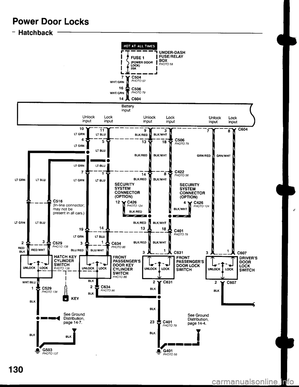
Power Door Locks
- Hatchback
T(
t.x
'o""f "
I
t" lf r8 lf e-l'-d;7o
-: --=--
I ",*".o ! "."*n., ! o"n",,
-l=+------+--,J,*.^
Lrcnr
I
tt "tu
l ar"u*,t
"LK FED
I
BLK*HT
I aa"ur,r,
I l3['"l,ii'o' I l3['*1,1t'o'
P,:r:-.^^--^,^.1 llTl'""'�
I I (oP'oN)
l'**'**"::;l | @! !:lX'**'-
'' "'i
[.'{,f - - - - =-d$*--T;.
- - - -
gl "":l ",*:.:["."::["*^ ."n",.1."n,n",
_.{____"lit':l;j".,,
^l .,"";1;,;.;T-------T--T*o',
;"*f t*t," "., ".'" ft;-if,
9,1#,, *- ^';tri::li
"..,
i "*l _ 2y
g:fi;"",," [l il'"8%," "* I-;
l-l
I s"" erouno
Bt^
|a r-< Diskibution. I see Ground
. oaoe 14-7. ,. J coot P:"^T1T19"'
I
n"o" t+ z ,"
f ,t"%%," pase r4_4.
="lj ==l-'---J
c607
DRIVER'SDOORLOCKswtTcH
UNDER-DASHFUSE/RELAYBOXFUSE 1
lR?;'-o"204
7
16WHT/GRN
14
c504
c506
c604
Batteryinput
Unlock Lockrnput inputUnlock Lockinput inputUnlock Lockirput input
raLT GRN I LT BLU
7 7--i
LI GRN I LT 8LU
_ _J_-jl c529 3 A r A COg+ BLK RED ll BLK wHr1 A cos+REO/BIK
PaAIA t18 l----J PHofo 86
HATCH KEY I....T...._TI FRONT I7-'Ft FRONTCYLTNDER | | ,-- llpassENGER,sl | | I PASSENGER'SSil''lt",i" I t-f-J lBeT*'ilS'*'l L-t-J I BA'"'fis8[:Igo_lr8 _ lulllgg!_l rocK I cyLtNDER I uNLocK I r-ocK I swtTcH--|--T---t lswrrclI l-rl-J PHoro 86
130
-1- Gs03 l-CaOt: PHOfO 137 - pHOfO
Page 1549 of 1681
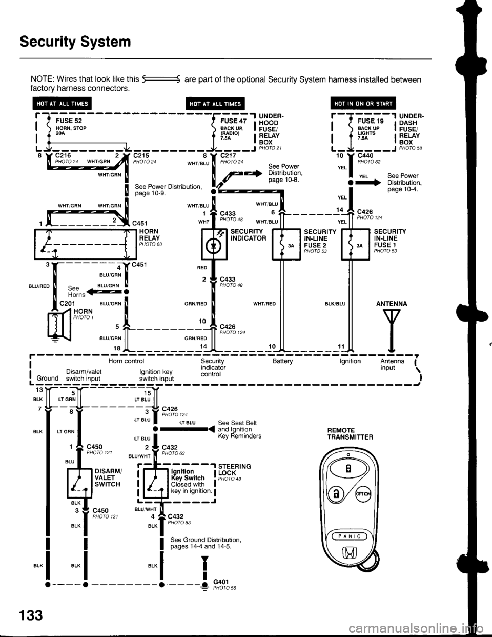
Security System
NOTE: Wires that look like this --::= are part of the optional Security System harness installed betlveen
factory harness connectors.
!-l-'*;;--
-----f.-u'?;l
HBB'J' !--T-'u-"-"-13X3"'*-| ) Ho-BN.srop ) B..l\-cj^qp I FUSE/ | ) Flg!!!p I FusE,| 1."^ | lTl"'", I RELAY I a ;'lx'" I RELAY| {--------------- l'* | Box I l -^ lBox
LJ--------.J4---------9----JP4oto21 L-Ja----JPHoro,3"\W27**^ -"hlT'jZn8:,*[:*ift :.1::t*'
seepowerpage 1o-8. a+ Distributjon,See Power Dislribulion. rZ)z----- I page 104.page 10-9.
''"' "t' 1.*"
*', "r:l-
- - - - - -,C **
, f]3,"0u, "1,f ";"3" *",J"11-------;'ff ;;;"
[F=]F;"#,.. kfl
t"ffBr+T'
EilHr{" E
mli
"."".:X-:-S]""'
"T['*-
ll ll
ffi'-"*FL_____r*F_*l
l^y^
c4s1 wnr I t"o'o 'o tn"r ".u | | ".. | | *n' ' '
i Horn control Security Battery lgnition Antenna Ia Horn control Security Battery lgnilion Antenna I
I Drsarm/varet rq indicator 'nPut \
: Ground switch input r.JllXi'lJ;,L control I! Ground switch input s'ivitcn inprlt IL------; ------Jtoy--T|f- -----,;]1
BrK ll rrGRNll LrBLU ll7 Yi- -;-lt- - - - - - -;-:t c426
"-l ,"":l :::lb.i[ri?n'a'fl:. r..rn?.,n| 'eru I Kev Reminders rRANsMlrrER
r
c4so z:L cqgz
:l-il*
",, I
ttu' . *'*'i'f, F;l'o"
rh d.,til i;-fr H{jfJ. I i{",;::*
Ed'"""" LliCir'l':i
":it*t*'
"t--,i[;""
I See Ground Distributron.I pages 14-4 and 14 5.
-.1
I
I
"..1
133
G401
Page 1558 of 1681
lnterlock System
- How the Circuit Works
Key Interlock
Battery voltage is supplied at all times through f use
33 to the key interlock switch. When the key is in
the ignition, battery voltage is supplied to the key
intedock solenoid and the key interlock circuit in the
interlock control unit. When the A/T gear position
switch is in PABK, ground is provided to the key
interlock circuit. This removes ground from the
interlock solenoid, the solenoid is deenergized, and
the key can be removed from the ignition.
Shift Position Interlock
Battery voltage is supplied at all times lrom fuse 52
to the brake switch. With the ignition in ON (ll) or
START (lll), battery voltage is supplied through luse
25 to the shift lock solenoid. When you push the
brake pedal, battery voltage is applied through the
GRN/VVHT wire to the transmission ('98-�99 models)
or powertrain ('00 model) control module (TCM or
PCM). lf, at the same time, you do not push the
accelerator pedal, a low voltage signal is sent
through the RED/BLK wire to the TCM or PCM. The
TCM or PCM then applies voltage through the
WHT/RED wire to the shift lock circuit in the
interlock control unit. lf the A,/T gear position switch
is in the PARK position, the shift lock circuit
provides ground to the shift lock solenoid. The
solenoid is then energized, and the shift lever can
be moved from the PARK Dosition.
Refer to the Service Manual (Section 23, Electrical)
for specific tests or troubleshooting procedures.
138-2
Page 1561 of 1681
Power Mirrors
- How the Gircuit Works
The two outside mirrors are controlled by the power
minor switch. Each mirror has two reversible
motors: one motor moves the mirror uo and down
and the other motor moves the mirror left and right.
The oower mirror switch contains three switches lo
control mirror direction, and two switches to select
the left or right mirror. With the ignition in ON (ll),
battery voltage is supplied to the power mirror
switch. The mirror selector switch directs voltage
from two of the direction switches to either the left
or the right minor. Each direction switch is used for
more than one function.
Mirror Up Operation
With the power mirror switch in the up position,
switch 1 is moved to the A oosition. Switch 1
applies battery voltage to both the left and right
power mirror up/down motors. lf the mirror selector
switch is in the left position, the left up/down motor
is grounded through the mirror selector switch and
switch 2 in the B position to G501 (Sedan) or G502
(Hatchback). lf the right mirror up/down motor is
selected il is also grounded through switch 2 in the
B position.
Mirror Down Operation
With the power mirror switch in the down position,
switches 2 and 3 are moved to the A position.
Switch 2 applies battery voltage to the left or right
power mirror up/down motor as determined by the
mirror selector switch. The selected mirror motor is
grounded through switch I in the B position to G501
(Sedan) or G502 (Hatchback). When switch 2 is
moved to position A, it also applies battery voltage
to the selected mirror lefyright motor. With switch 3
in the A position, battery voltage is supplied to both
sides of the leruright motor so it does not move.
Mirror Left Operation
With the power mirror switch in the left position,
switches 1 and ? ate moved to the A oosition.
Switch 2 applies battery voltage to the left or right
power mirror lefvright motor as determined by the
mirror selector switch. The selected mirror motor is
grounded through switch 3 in the B position to G501
(Sedan) or G502 (Hatchback). When switch 2 is
moved to position A, it also applies battery voltage
to the selected mirror up/down molor. With switch 1
in the A position, battery voltage is supplied to both
sides of the uD/down motor so it does not move.
Mirror Right Operation
With the power mirror switch in the right position,
switch 3 is moved to the A position. Switch 3
applies battery voltage through the mirror selector
switch to the left or right lefvright motor. The
motor is grounded through the mirror selector
switch and switch 2 in the B oosition to G501
(Sedan) or G502 (Hatchback).
Refer to the Service Manual (Section 23, Electrical)
for specific tests or troubleshooting procedures.
141-2