boot HONDA INTEGRA 1998 4.G User Guide
[x] Cancel search | Manufacturer: HONDA, Model Year: 1998, Model line: INTEGRA, Model: HONDA INTEGRA 1998 4.GPages: 1681, PDF Size: 54.22 MB
Page 636 of 1681
Disassembly
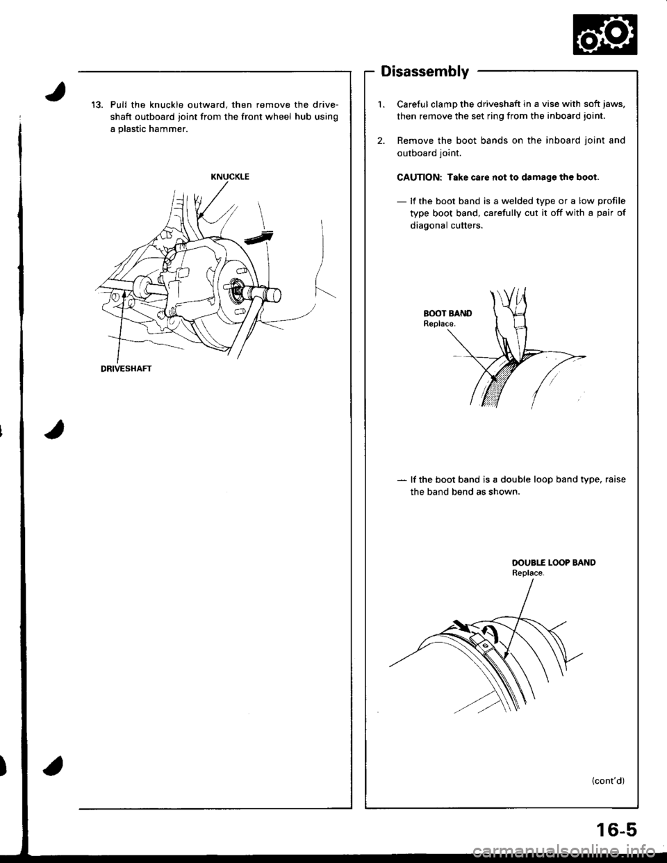
13. Pull the knuckle outward. then remove the drive-
shaft outboard joint from the front wheel hub using
a plastic hammer.
KNUCKLE
DRIVESHAFT
l.Careful clamp the driveshaft in a vise with soft jaws,
then remove the set ring from the inboard joint.
Remove the boot bands on the inboard ioint and
outboard joint.
CAUTION: Take care not to damags th€ boot.
- lf the boot band is a welded type or a low profile
type boot band, carefully cut it off with a pair of
diagonal cutters.
2.
- lf the boot band is a double loop band type, raise
the band bend as shown.
OOUBI-E LOOP BANDReplace.
(cont'd)
16-5
Page 637 of 1681
Driveshafts
Removal lcont'd)
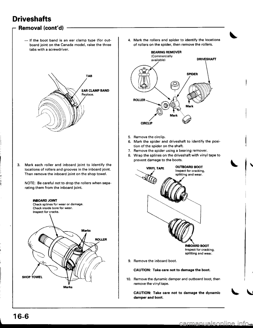
- lf the boot band is an ear clamp
board joint on the Canada mode
tabs with a screwdriver.
type {for out-
raise the three
EAR CLAMP BAND
3. Mark each roller and inboard joint to identify the
locations of rollers and grooves in the inboard joint.
Then remove the inboard joint on the shop towel.
NOTE: Be careful not to drop the rollers when sepa-
rating them from the inboard joint.
NBOAND Jo|NNCheck splines for wear or damage.Check inside bore lor wear.lnsoect for cracks.
Marla
4. Mark the rollers and spider to identify the locations
of rollers on the spider, then remove the rollers.
VI'{YL T
,%
BEARING REMOVER(Commercially
available)
5. Remove the circlip.
6. Mark the spider and driveshaft to identify the posi-
tion of the soider on the shaft.
7. Remove the spider using a bearing remover,
8. Wrap the splines on the driveshaft with vinyltape to
prevent damage to the boots.
APE ouTBoaRD BOOTInsp€ct ror crackrng,splitting and wear.
Inspect for cracking,splitting and woar.
Remove the inboard boot.
GAUTION: Tako care noi to damsge the boot.
Remove the dynamic damper and outboard boot. then
remove the vinyl tape.
CAUTION: Take care not to damage the dynamic
dampor and boot.
10.
16-6
\
Page 639 of 1681
Driveshafts
LEFT INBOARD JOINT
DYNAMIC DAMPER
Reassembly
NOTE:
. Clean the disassembled parts with solvent, and dry them thoroughly with compressed air. Do not wash the rubber
parts with solvent.
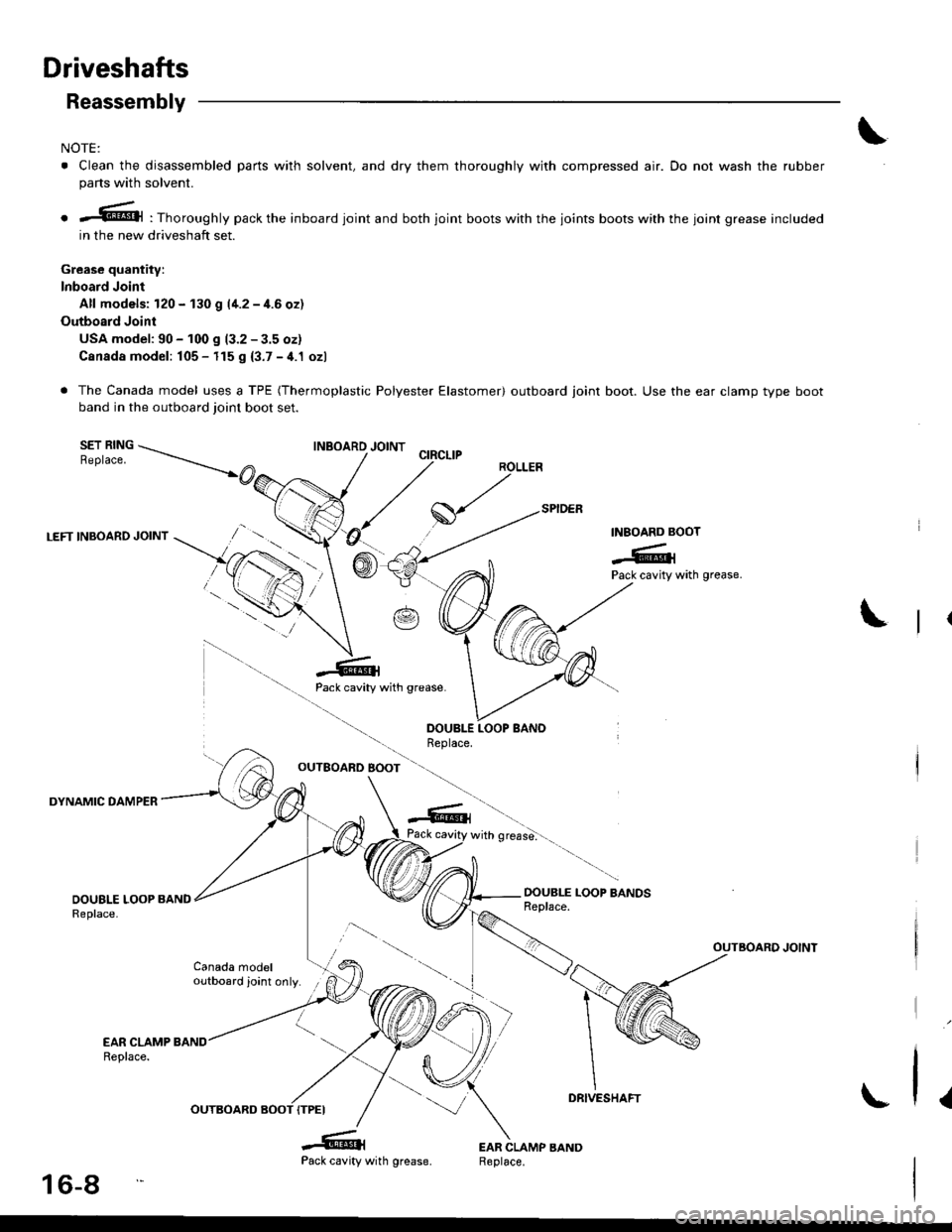
o -@l : Thoroughly pack the inboard joint and both joint boots with the joints boots with the joint grease included
in the new driveshaft set.
Grease quantity:
lnboard Joint
Alf models: 120 - 130 g l1-2 - 1.6 ozl
Outboard Joint
USA model: 90 - 100 S 13.2 - 3.5 oz)
Canada model: 105 - 115 g {3.7 - 4.1 ozl
. The Canada model uses a TPE (Thermoplastic Polyester Elastomer) outboard joint boot. Use the ear clamp type boot
band in the outboard joint boot set.
SET RINGReplace.
INBOARD BOOT
-#,1Pack cavity with grease.
Pack cavity with grease.
OUTEOARD BOOT
with grease''
OOUBLE LOOP BANDSReplace.
OUTBOARD JOINT
Canada modeloutboard joint only.
l.
-6{Pack cavity
INBOARD JOINT
DRIVESHAFT
16-8
OUTBOARD
wrln grease,
Page 640 of 1681
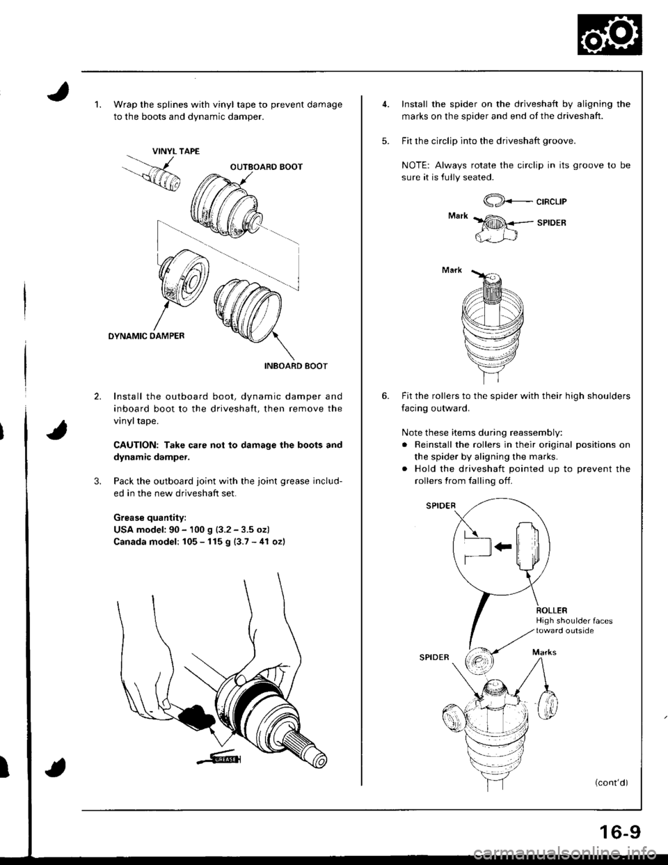
1.Wrap the splines with vinyl tape to prevent damage
to the boots and dvnamic damoer.
VINYL TAPE
OYNAMIC DAMPER
INBOARD BOOT
2. Install the outboard boot, dynamic damper and
inboard boot to the driveshaft, then remove the
vinyltape.
CAUTION: Take care not to damage the boots and
dynamic damper.
3. Pack the outboard joint with the joint grease includ-
ed in the new driveshaft set.
Grease quantily:
USA model: 90 - 100 g (3.2 - 3.5 oz)
Canada model: 105 - 115 g (3.7 - 41 oz)
I
5.
Install the spider on the driveshaft by aligning the
marks on the spider and end of the driveshaft.
Fit the circlip into the driveshaft groove.
NOTE: Always rotate the circlip in its groove to be
sure it is fully seated.
@*c'nc'-'t
SPIDEB
6. Fit the rollers to the spider with their high shoulders
facing outward.
Note these items during reassembly:
. Reinstall the rollers in their original positions on
the spider by aligning the marks.
. Hold the driveshaft pointed up to prevent the
rollers from falling off.
High shoulder {aces
Marks
(cont'd)
SPIOER
16-9
Page 641 of 1681
Driveshafts
Reassembly (cont'd)
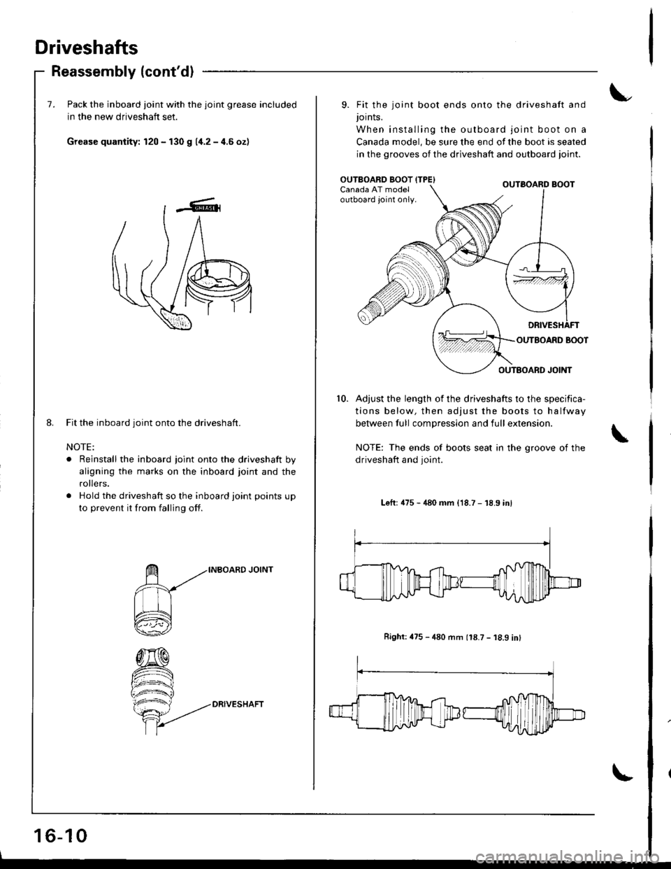
7. Pack the inboard joint with the joint grease included
in the new driveshaft set.
Grease quantity: 120 - f30 g 11.2-4.6ozl
Fit the inboard joint onto the driveshaft.
NOTE:
. Reinstall the inboard joint onto the driveshaft by
aligning the marks on the inboard joint and the
ro ers.
. Hold the driveshaft so the inboard joint points up
to p.event it from falling off.
DRIVESHAFT
16-10
8.
9. Fit the joint boot ends onto the driveshaft and
Jornts.
When installing the outboard joint boot on a
Canada model, be sure the end of the boot is seated
in the grooves of the driveshaft and outboard ioint.
Adjust the length of the driveshafts to the specifica-
tions below, then adjust the boots to halfway
between full compression and full extension.
NOTE: The ends of boots seat in the groove of the
driveshaft and joint.
Lefr: 475 - 480 mm {18.7 - 18.9 inl
Right:475 - 480 rnm (18.7 - 18.9 int
10.
OUTBOARD BOOT {TPE)Canada AT modeloutboard joint only.
Page 642 of 1681
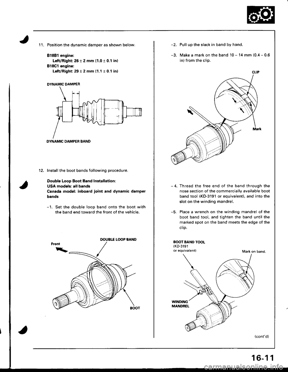
1 1. Position the dynamic damper as shown below.
81881 engine:
Left/Right: 26 t 2 mm 11.0 t 0.1 in)
BlSCl engins:
Left/Right: 29 t 2 mm (1.1 i 0.1 in)
DYNAMIC DAMPER
DYNAMIC DAMPER BAND
12. Install the boot bands following procedure.
Double Loop Boot Band lnstallalion:
USA models: all bands
Canada model: inboard ioint and dynamic dampel
bands
-1. Set the double loop band onto the boot with
the band end toward the front of the vehicle.
L(X)P BANODOUBI.f
/
-')Pull up the slack in band by hand.
Make a mark on the band 10 - 14 mm (0.4 - 0.6
in) from the clip.
Thread the free end ot the band through the
nose section of the commercially available boot
band tool (KD-3191 or equivalent), and into the
slot on the winding mandrel.
Place a wrench on the winding mandrel of the
boot band tool, and tighten the band until the
marked spot on the band meets the edge of the
clrp,
-5.
BOOT BAND TOOLlKD-3191o. equivalent)Mark on band.
(cont'd)
CLIP
16-1 1
Page 643 of 1681
Driveshafts
Reassembly (cont'dl
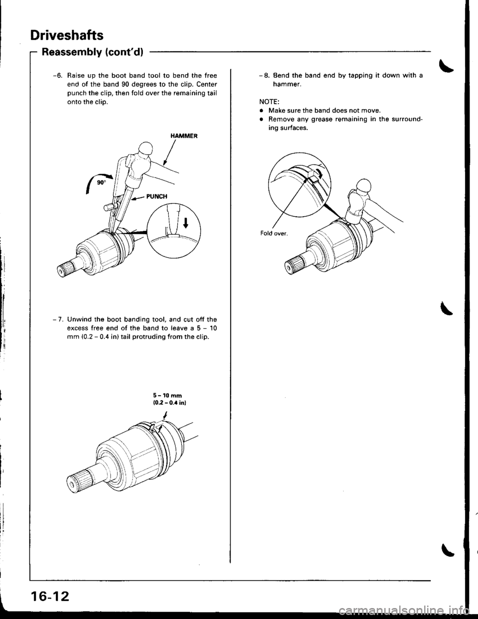
-6. Raise up the boot band tool to bend the free
end of the band 90 degrees to the clip. Center
punch the clip, then fold over the remaining tail
onto the clio.
- 7. Unwind the boot banding tool, and cut off the
excess free end of the band to leave a 5 - '10
mm (0.2 - 0.4 in) tail protruding from the elip.
HAMMER
5- 10 mm(0.2 - 0.a inl
16-12
- 8. Bend the band end by tapping it down with a
nammer.
NOTE:
. Make sure the band does not move.
. Remove any grease remaining in the surround-
ing surfaces.
Page 644 of 1681
![HONDA INTEGRA 1998 4.G User Guide E8r Clamp Type Boot Eand Installation:
Csnada model outboard joi]|t bands
-1. Install the ear clamp boot band by aligning the
tabs with holes in the band.
EAR CLAMP BANDReplace.
Close the ear portion HONDA INTEGRA 1998 4.G User Guide E8r Clamp Type Boot Eand Installation:
Csnada model outboard joi]|t bands
-1. Install the ear clamp boot band by aligning the
tabs with holes in the band.
EAR CLAMP BANDReplace.
Close the ear portion](/img/13/6069/w960_6069-643.png)
E8r Clamp Type Boot Eand Installation:
Csnada model outboard joi]|t bands
-1. Install the ear clamp boot band by aligning the
tabs with holes in the band.
EAR CLAMP BANDReplace.
Close the ear portion of the band with a com-
mercially available boot band pincers.
BOOT AAND PINCERS(Commercially available)Oetiker 1098 or equivalent
POSTION
Measure the clearance between the closed ear
portion of the band.
Siandard:0-3 mm (0 - 0.12 in)
lf the band's, clearance is not within the standard,
close the ear portion of the band further.
NOTE:
. Make sure the band does not move.
. Remove any grease remaining in the surround-
ing surfaces.
16-13
Page 646 of 1681
Intermediate Shaft
Removal
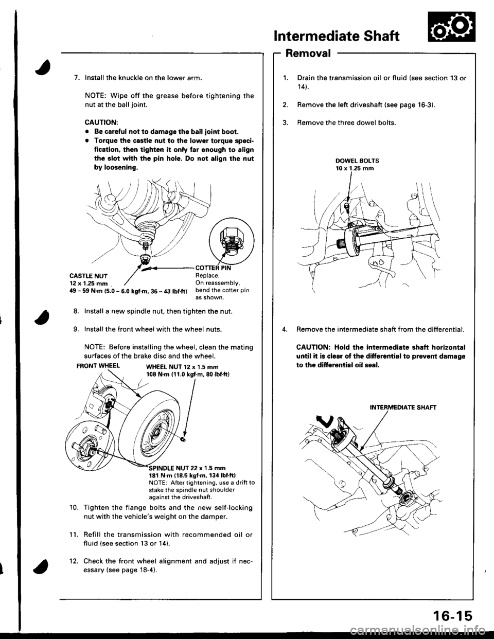
Drain the transmission oil or fluid {see section 13 or
14t.
Remove the left driveshaft (see page 16-3).
Bemove the three dowel bolts.
Remove the intermediate sh8ft from the differential.
CAUTION: Hold the intermediate shaft horizontal
until it is clear ot th6 difforantirl to prevont damage
to thc ditf€rential oil seal.
7. Install the knuckle on the lower arm.
NOTE: Wipe off the grease before tightening the
nut at the ball joint.
CAUTION:
. Be careful not to damago the ballioint boot.
. Torque the castle nut to tho low€r torque speci-
tication, then tighten it only lar onough to align
th6 slot whh tho pin hols. Do not align the nut
by loosening.
,.<__coTTEF PtNCASTLE NUT12 x 1.25 mm49 - 59 N.m {5.0 - 5.0 kgf.m, 36 - t3 lbl.ft)
Beplace.On reassembly,bend the cotter pin
8. Install a new spindle nut, then tighten the nut.
9. Installthe front wheel with the wheel nuts.
NOTE: Before installing the wheel, clean the mating
surfaces of the brake disc and the wheel.
FRONT WHEELWH€EL NUT 12 x 1.5 mm108 N.m (11.0 kgt m,80lbf ft)
10.
NUT 22 x '1.5 mm181 N m 118.5 kgl.m, 134lbtftlNOTE: After tightening, use a drift tostake the spindle nut shoulderagainst the driveshatt.
Tighten the flange bolts and the new self-locking
nut with the vehicle's weight on the damper.
Refill the transmission with recommended oil or
fluid (see section 13 or 14).
11.
12. Check the front wheel alignment and adjust if nec-
essary (see page 18-4).
INTERMCOIATE SHAFT
16-15
Page 650 of 1681
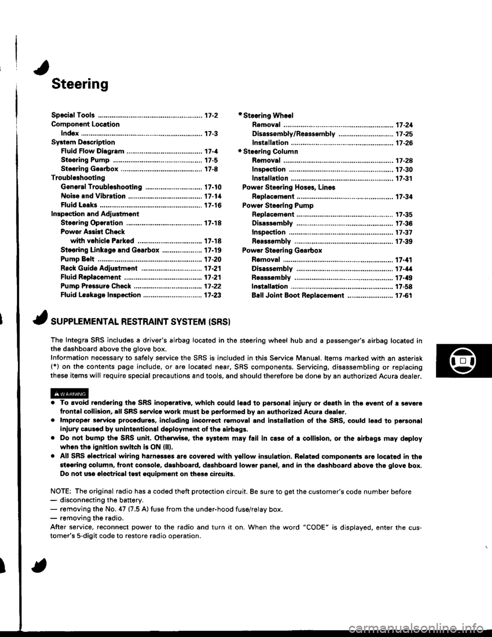
Steering
Componsnt Location
lndox
*Stooring Wheel
Removal ....
Disassombly/Ro8$.mbly
Disassombly ......
F08$€mbly
Powcr Stosring Gosrbox
R6moval
............................ 17-3
............. 17 -1
................ 17-16
............................. 17_25
17-30
17.31
.......17-21
Sy3tom DGcription
Fluid Flow Disgram
Steering Pump .............. 17-5
Stocring Goarbox ...17.8
Troublorhooting
Gonoral Troubleshooting .............................. 17.10
Noiso lnd Vibration ...... 17-1i[
Fluid Losk3
lnspoction
Installation
Powor Steering Hos6, Lino3
Roplacom€nt .................. 17.34
Powor Steoring Pump
RGplac6montlolpeqtion lnd Adiu3tm6nl
Stoo.ing Operation
Powor A$bi Chock
with v.hiclo Parked
Stcering Linkage 6nd Goarbox
Pump Bolt
17.18
17.18
17.19
17-20
17.35
t7-36
17 -37
r7-39
Inspoction
................... 17.41
Rack Guide Adiustmont ..........................-.-.-. 17 -21
Ffuid Rcplacemont ........17-21
Pump Prc&suro Chock ...,........................,..,..., 17 -22
Fluid Leakage Inrpection ............................... 17-23
Dissssembly
R€aEs€mbly
In3tallation........... 17_58
Ball Joint Boot Replacem.ni ........................ 17-61
17-U
17.49
J ,urrar*TNTAL REsrRArNr sysrEM (sRsr
The Integra SRS includes a driver's airbag located in the steering wheel hub and a passenger's airbag located inthe dashboard above the glove box,
Information necessary to safely service the SRS is included in this Service Manual. ltems marked with an asterisk(*) on the contents page include, or are located near, SRS components. Servicing, dissssembling or replacing
these items will require special pr6cautions and tools, and should therefore be done by an authorized Acura dealer.
. To avoid rondoring ths SRS inoparstivo. which could |rad to parsonal iniury or doath in the ov€nt of ! sev6.o
trontal collision, all SRS sarvice work must be perto.med by an authorizod Acura dsalor.. lmpropor 3orvic€ procadures, including inco[6ql rgmoval and inrtallation of the SRS, could l6ad to pgrsonal
iniury clus€d by unintentional doployment of the airbags,. Do nol bump tho SRS unh, (Xherwise, th6 3ystom may fail in cas€ ol a collision, or the airbags may d€ploy
when ths ignition switch is ON {ll).. All SRS electrical wiring harness€s aro covered with yallow insulation. Related component3 are located in ths
stcaring column. tront con3ol6, dashboard, d.shbolrd lower panel, and in the dashboard above ths glove box.
Do not u3o electrical test oquipm€nt on the3e circuii3.
NOTE: The original radio has a coded theft protection circuit. Be sure to get the customer's code number before- disconn€cting the battery.- removing the No. 47 (7.5 A) fuse from the under-hood fuse/relay box,- removing the radio.
After service, reconnect power to the radio and turn it on. When the word "CODE" is displayed. enter the cus-
tomer's 5-digit code to restore radio operation.